Project-1: Powertrain for aircraft in runways
Part A:
Que.1: Search and list out the total weight of various types of aircrafts.
Ans:
The different terms represent different weights or masses. For each flight, the weights are taken into account for several reasons. A brief description about these is below:
Manufacturer's empty weight (MEW): Also called Manufacturer's Weight Empty (MWE) or Licensed Empty Weight. It is the weight of the aircraft "as built" and includes the weight of the structure, power plant, furnishings, installations, systems and other equipment that are considered an integral part of an aircraft. This excludes any baggage, passengers, or usable fuel.
Zero-fuel weight (ZFW): This is the total weight of the airplane and all its contents (including unusable fuel), but excluding the total weight of the usable fuel on board. As a flight progresses and fuel is consumed, the total weight of the airplane reduces, but the ZFW remains constant. Maximum zero fuel weight (MZFW) is the maximum weight allowed before usable fuel and other specified usable agents (engine injection fluid, and other consumable propulsion agents) are loaded.
Operating empty weight (OEW): (Roughly equivalent to basic empty weight on light aircraft). It is the basic weight of an aircraft including the crew, all fluids necessary for operation such as engine oil, engine coolant, water, unusable fuel and all operator items and equipment required for flight but excluding usable fuel and the payload.
Payload: It is the carrying capacity of an aircraft. It includes cargo, people, extra fuel. In the case of a commercial airliner, it may refer only to revenue-generating cargo or paying passengers.
Maximum take-off weight (MTOW): This is the maximum weight at which the pilot of the aircraft is allowed to attempt to take off.
Regulated take-off weight (RTOW): Depending on different factors (e.g., flap setting, altitude, air temperature, length of runway), RTOW or maximum permissible take-off weight varies for each take-off. It can never be higher than MTOW.
Maximum landing weight (MLW): This maximum weight at which an aircraft is permitted to land.
The following image depicts take-off weight components.
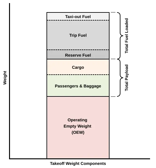
Maximum ramp weight (MRW): also called maximum taxi weight (MTW). It is the maximum weight authorized for maneuvering (taxiing or towing) an aircraft on the ground.
Aircraft gross weight: It is the total aircraft weight at any moment during the flight or ground operation. This decreases during flight due to fuel and oil consumption.
Below is a table of some of the most common aircraft flying around our skies today:
| Aircraft | Empty Weight | Max Fuel Weight | Max Cargo Weight | Max Gross Takeoff Weight |
|---|---|---|---|---|
| Antanov AN-225 | 628,000 lbs 285,000 kg |
661,400 lbs 300,000 kg |
417,000 lbs 190,000 kg |
1,411,000 lbs 640,000 kg |
| Airbus A380-800 | 611,000 lbs 277,000 kg |
560,000 lbs 254,000 kg |
185,000 lbs 84,000 kg |
1,268,000 lbs 575,000 kg |
| Boeing 747-800 | 485,300 lbs 220,100 kg |
427,400 lbs 194,000 kg |
295,000 lbs 134,000 kg |
987,000 lbs 447,700 kg |
| Airbus A340-500 | 370,000 lbs 168,000 kg |
386,300 lbs 175,000 kg |
119,000 lbs 54,000 kg |
820,000 lbs 372,000 kg |
| Boeing 777-300ER | 370,000 lbs 168,000 kg | 320,800 lbs 145,500 kg | 148,000 lbs 67,100 kg |
776,000 lbs 352,000 kg |
| Boeing 787-10 | 299,000 lbs 135,500 kg | 223,500 lbs 101,500 kg |
126,300 lbs 57,300 kg | 560,000 lbs 254,000 kg |
| Boeing 737-900 | 98,500 lbs 44,700 kg |
53,100 lbs 24,000 kg |
44,600 lbs 20,200 kg |
187,000 lbs 85,000 kg |
| Airbus A320-100 | 93,900 lbs 42,600 kg |
48,700 lbs 22,100 kg |
44,000 lbs 20,000 kg |
150,000 lbs 68,000 kg |
| Embraer 190 | 63,500 lbs 28,800 kg |
28,600 lbs 13,000 kg |
28,800 lbs 13,100 kg |
106,000 lbs 48,000 kg |
| Gulfstream G650 | 54,000 lbs 24,500 kg | 48,200 lbs 21,900 kg | 6,500 lbs 3,000 kg |
100,000 lbs 45,200 kg |
| Bombardier CRJ900 | 48,160 lbs 21,850 kg | 19,600 lbs 8,900 kg | 6,075 lbs 2,760 kg | 80,500 lbs 36,500 kg |
| Bombardier Q400 | 39,300 lbs 17,800 kg |
11,700 lbs 5,300 kg |
18,700 lbs 8,500 kg |
62,000 lbs 28,000 kg |
| Learjet 75 | 13,900 lbs 6,300 kg | 6,060 lbs 2,750 kg |
2,900 lbs 1,300 kg |
21,500 lbs 9,700 kg |
| Cessna Citation CJ4 | 10,300 lbs 4,700 kg | 5,800 lbs 2,650 kg |
2,200 lbs 1,000 kg | 17,200 lbs 7,800 kg |
| Beechcraft King Air B100 | 7,100 lbs 3,200 kg | 3,200 lbs 1,450 kg |
4,150 lbs 1,900 kg |
12,000 lbs 5,400 kg |
| Diamond DA50 RG | 3,200 lbs 1,450 kg |
340 lbs 155 lbs |
1,250 lbs 560 kg |
4,400 lbs 2,000 kg |
| Beechcraft Bonanza G36 | 2,500 lbs 1,150 kg | 450 lbs 200 kg |
850 lbs 385 kg |
3,660 lbs 1,660 kg |
| Cessna 206H | 2,200 lbs 990 kg |
520 lbs 235 kg |
1,150 lbs 520 kg |
3,600 lbs 1,630 kg |
| Sirrus SR22 | 2,250 lbs 1,000 kg | 485 lbs 220 kg |
950 lbs 430 kg |
3,600 lbs 1,630 kg |
| Cessna 172R | 1,700 lbs 770 kg |
380 lbs 170 kg |
560 lbs 255 kg |
2,425 lbs 1,100 kg |
Que.2: Is there any difference between ground speed and air speed?
Ans:
Generally speaking, there are two different types of speed when talking about airplanes: ground speed and airspeed.
Ground speed is the airplane’s speed relative to the surface of the Earth, airspeed – at least true airspeed – is its speed relative to the air it is flying in.The relationship between airspeed and ground speed is fairly simple. Ground speed is simply the sum of airspeed and wind speed. If the aircraft is flying in the same direction as the wind is blowing, the aircraft experiences tailwind, and its ground speed is higher than its airspeed. On the other hand, if the wind is blowing against the direction the aircraft is traveling in, the aircraft experiences headwind, and its ground speed is lower than its airspeed.
As an airplane climbs, it ascends into thinner air. The thinner air creates less air pressure in the pitot tube (which measures airspeed), and so the indicated airspeed is lower than the airplane’s true airspeed. Thus, as an airplane climbs, its indicated airspeed gets lower and lower compared to its true airspeed.
Ground speed, however, also depends on the winds. An airplane that climbs into an increasing headwind will see a corresponding decrease in its ground speed compared to if it climbed into still air. If it climbs into an increasing tailwind, its ground speed will increase.
So, in general, the relationship between indicated airspeed and ground speed as an aircraft changes altitude depends on the direction and magnitude of the winds at that altitude.
Que.3: Why is it not recommended to use aircraft engine power to move it on the ground at Airport?
Ans:
For movement on the ground the aircraft uses it own engine power, which is called taxing.Aircraft move using their own engine power all the time on the airport apron and taxiways under their own power to go towards runways and after landing taxi to their assigned gate.Although many aircrafts are capable of moving in backward using reverse thrust, as result the jet blast or prop wash might cause damage to the terminal building or equipment. Engine close to ground may also blow sand and debris forward and then suck them into the engine, causing damage to the engine. Therefore there are pushback trucks in the airport. A pushback truck lifts the front wheel of the aircraft, their role in most airports is to move the aircraft away from the parking spot on to the taxiways, which is called towing.
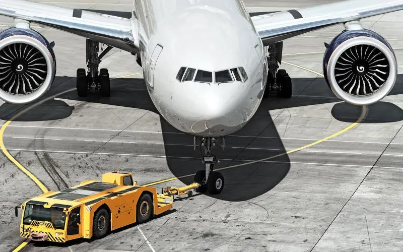
Fig.An aircraft towed by a tug.
Unwanted consequences mainly arising from the unintended movement of the aircraft during engine running.
i) Effectively a loss of control can happen, especially during high power engine running. Damage can occur to the aircraft itself, other aircraft nearby or to airside structures.
ii) There is a risk of injury to ground support personnel who may be in relatively close proximity to the aircraft.
iii) Aircrafts are usually ‘pushed’ by ground vehicles known as tow vehicles, the reason I stress pushed, is because it is used mainly to reverse an airplane from the terminal area, until it is in a position to move by itself. So, it is easier for truck driver to see the surroundings better than the pilot sitting in the cockpit with limited window. The pushback driver knows the airport better than the pilot.
iv) It also saves fuel. virgin Atlantic had proposed a new system in which pushback truck will move the aircraft all the way to runway to save fuel and reduce impact of environment.
v) The plane engines are very loud. When more than one plane will add up their sound, than it will not be pleasent for passangers and others near airport.
let us come to why the aircraft needs to pushed back in the first place:
Aircrafts don’t have powered wheels, and hence cannot move in reverse (let alone forward by themselves). Imagine a tiny jet strapped to one of your toy cars; that’s essentially how airplanes work on the ground! They go where the engines push them towards. (Note: There is a mechanism known as reverse thrusters, which allow the engine air flow to be pushed towards the front, but that is highly risky maneuver, and is only used to reduce speed immediately after landing.)
Another reason to push back an aircraft to a safe area, is for safety reasons. The engines produce tremendous thrust from the exit, and an immense vacuum from the front; enough to suck in people, small vehicles, ground equipment etc
So, for above reason it is not recommended to use aircraft engine power to move it on the ground at Airport.
Que.4: How an aircraft is pushed to runway when its ready to take off?
Ans:
Airplanes have engines, and they can use them to move forward along the ground. So they push themselves to the runway.It is true that most of the time, a small vehicle is needed to push the larger commercial airplanes backwards away from the terminal building, because even if a plane can reverse it’s thrust, it’s not always safe to hit the buildings with that reverse thrust. So the little trucks push the bigger planes back away from the buildings, but after that, the planes can apply a small amount of engine power to roll forward just as all airplanes can.Aircraft push themselves to the runway.
TOWING: Pushbacks at busy aerodromes are usually subject to ground control clearance to facilitate ground movement on taxiways. Once clearance is obtained, the pilot will communicate with the tractor driver (or a ground handler walking alongside the aircraft in some cases) to start the pushback. To communicate, a headset may be connected near the nose gear.
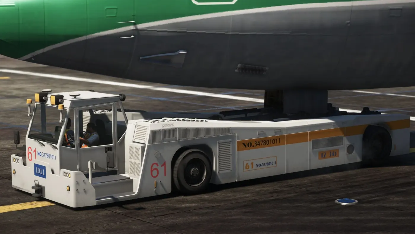
Fig. Aircraft towing vehicle (Towbarless Tug).
Since the pilots cannot see what is behind the aircraft, steering is done by the pushback tractor driver and not by the pilots. Depending on the aircraft type and airline procedure, a bypass pin may be temporarily installed into the nose gear to disconnect it from the aircraft's normal steering mechanism. Once the pushback is completed, the towbar is disconnected, and any bypass pin removed. The ground handler will show the bypass pin to the pilots to make it clear that it has been removed. The pushback is then complete, and the aircraft can taxi forward under its own power.
TAXIING: Taxiing (rarely spelled taxying) is the movement of an aircraft on the ground, under its own power, in contrast to towing or pushback where the aircraft is moved by a tug. The aircraft usually moves on wheels, but the term also includes aircraft with skis or floats (for water-based travel). An airplane uses taxiways to taxi from one place on an airport to another; for example, when moving from a hangar to the runway. The term "taxiing" is not used for the accelerating run along a runway prior to takeoff, or the decelerating run immediately after landing, which are called the takeoff roll and landing rollout, respectively.
Fig. Aircraft Taxxing.
Takeoff is the phase of flight in which an aerospace vehicle leaves the ground and becomes airborne. For aircraft traveling vertically, this is known as liftoff. For aircraft that take off horizontally, this usually involves starting with a transition from moving along the ground on a runway. For balloons, helicopters and some specialized fixed-wing aircraft (VTOL aircraft such as the Harrier), no runway is needed.
Que.5: Learn about take off power, tyre design, rolling resistance, tyre pressure, brake forces when landing.
Ans:
i)Take off power:The amount of power that an engine is allowed to produce for a limited period of time for take-off. The use of takeoff power is usually limited to 5 min for reciprocating engines and up to 2½ min for gas turbine engines. This may not always be the case. Specifically, with respect to reciprocating engines, it is the brake horsepower developed under standard, sea-level conditions and under the maximum conditions of the crankshaft rotational speed and the engine manifold pressure approved for the normal take-off. It is limited in continuous use to the period of time shown in the approved engine specifications. With respect to gas turbine engines, it is the thrust developed under static conditions at a specified altitude and atmospheric conditions of the rotor shaft rotational speed and gas temperature approved for the normal take-off. It is limited in continuous use to the period of time shown in the approved engine specifications.
During take-off the aircraft goes through a transition from ground on a runway to flying in the air. After taxing up to the starting of the runway, the aircraft is stopped. The engines are run at full power to check for engine related problems. The pilot then releases the brakes, when the aircraft is accelerated rapidly until the necessary speed for take-off is achieved. The take of speed varies depending on the weight of the aircraft, the density of air and aircraft configuration. The air density depends on the position of the airport from sea level and the atmospheric temperature. The required take off speed is to be achieved in case the aircraft has to take off which also depends on the length and slope of the runway.
The take-off speed is relative to the motion of the air. In case of a head wind the take-off speed is much less as there is greater flow of air over the wings. Hence the aircrafts usually take off against the wind. Side wind is usually not preferred as this could disturb the stability of the aircraft. The take-off speeds for the jetliners are usually 240 to 285 Km/hr and is directly proportional to the weight of the aircraft. Some aircraft have difficulty in generating enough lift during take-off. In such cases they are fitted with high lift devices which includes slats and usually flaps which increases the camber of the wings which creates more lift at low speeds. Just after the climb phase, the wheels are retracted into the aircraft and undercarriage doors are closed making the aircraft more aerodynamic.
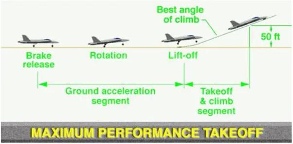
Fig.Aircraft Take-off.
Take-off power calculations:
In the physics real Power= Mass x Acceleration x distance/time.
To many it means "how much throttle" , which is how much fuel/time.
"Throttle" x prop efficiency = Thrust
This gives you a unit of Force that can be directly compared to glide data as follows:
Potential energy Mass x Gravity x altitude loss = Thrust x horizontal distance flown
This rearranged to,
Thrust = Mass x Gravity x altitude loss/horizontal distance flown
Thrust = force required for straight and level flight, expressed in "pounds or Newtons".
So, if your plane weighs 10 lb and glides 5:1, you need 2 lb of thrust for straight and level flight. One would at least double, or even triple this for "takeoff power", depending on your performance preferences. Sufficient "takeoff power" will give a safe climb rate to avoid difficulties with downdrafts.
For example: my plane glides 5:1 at 60 mph or around 5000 feet/minute and loses 1000 feet/minute. At 10 lbs it was calculated to need 2 lbs of thrust for straight and level flight. Then how much more thrust do we need to climb 500 feet per/minute. Again, the glide data provides a very good estimate, 2 lbs x 500 fpm/1000 fpm = 1 lb additional or 3 lbs total at 60 mph. Higher speeds with more drag, or lower speeds "behind the power curve" will require more than 3 lbs of thrust.
ii)Tyre design:Aircraft tires are totally different from common automobile tires & are amazing when you think about it. They have many layers under the rubber which holds the pressurized air inside it intact. They are strong enough & are designed to endure extremely heavy loads for short durations at high speeds. While landing they get heated anywhere between 130 - 150 degree Celsius. At this extreme environment it is required to maintain structural integrity as lives depend on it. Needless to say they need replacement (or re-threading) every 150–250 cycles (take-offs & landings). The brakes need replacement after 2000 odd cycles.
Fig. 28 tires (14 sets of 2 tires each) on the world’s largest aircraft An-225 Mriya. These monsters take the maximum weight of 640 tons.
To answer how exactly they survive the extreme torture of landings lets look into few details of aircraft tires:
Inner Layers: The inner layers of aircraft tires have multiple layers of nylon, Kevlar or aramid which contributes to its load bearing and air pressure resisting capabilities. It is these material & not rubber which withstands the monumental circumferential stress that’s there inside the tire. FYI, Kevlar & aramid are the same material which is used to make bullet proof vests. Kevlar is 6 times stronger than steel.
Fig. Cross section of a Bridgestone aircraft tire.
Pressure: The key to the remarkable durability of an aircraft tire is maximizing the air pressure. With enormous pressures, a very small surface area of the tire is in contact with the runway & hence the friction is less. Also it creates lesser drag & hence the end result is lesser heat generation.
- A typical car tire is pumped at 30–35 psi.
- Typically airliner tires are inflated to 220 psi. Tires on an F-16 fighter are pumped to 320 psi.
- The test pressure of these tires is 800 psi.
For comparison, a typical submarine at its test depth of 350 meters under water can take up only up to 514 psi with more than 1 foot thick hull made up of solid iron.
Nitrogen: When tires spin, the rubber faces extreme friction with the runway. This creates immense heat. If normal air is filled in the tire, the oxygen in the air gets mixed with volatile gases, thus overheating the tire & eventually exploding upon reaching the auto-ignition temperature. To counter this effect, the tires of aircraft are filled with dry nitrogen. Nitrogen being (inert gas) non flammable, not easily compressible, minimizes expansion and contraction from extreme changes in ambient temperature and pressure experienced during flight
Weight distribution: To reduce the pressure on each tire, the weight of the aircraft is distributed among a set of tires on the main landing gear. This dramatically reduces the stress a single tire faces. There are usually 2 or 4 sets of main landing gears which take the most amount of weight of the aircraft apart from the nose landing gear.
Types of Tyre used & their constructions:
A)Based on the type of plies used the tyres can be:
Radial ply tires: These tyres feature a flexible casing which is constructed of rubber-coated ply cords which extend around the beads and are substantially at 90° to the centerline of the tread. The casing is stabilized by an essentially inextensible circumferential belt. Radial tires are the most modern design of aircraft tyres. It is a design that is similar to that of car tyres. Typically, the radial tyre offers more landings per tread and lighter weight than a bias tyre; though sometimes at the expense of retread lives. Radial aircraft tyres differ to bias aircraft tyres in that the plies all run radially from bead to bead at approximately 90° to the centre-line of the tyre. Angled belt plies are laid between the tread and the top casing ply, resulting in a flatter tread and adding strength to the tyre.
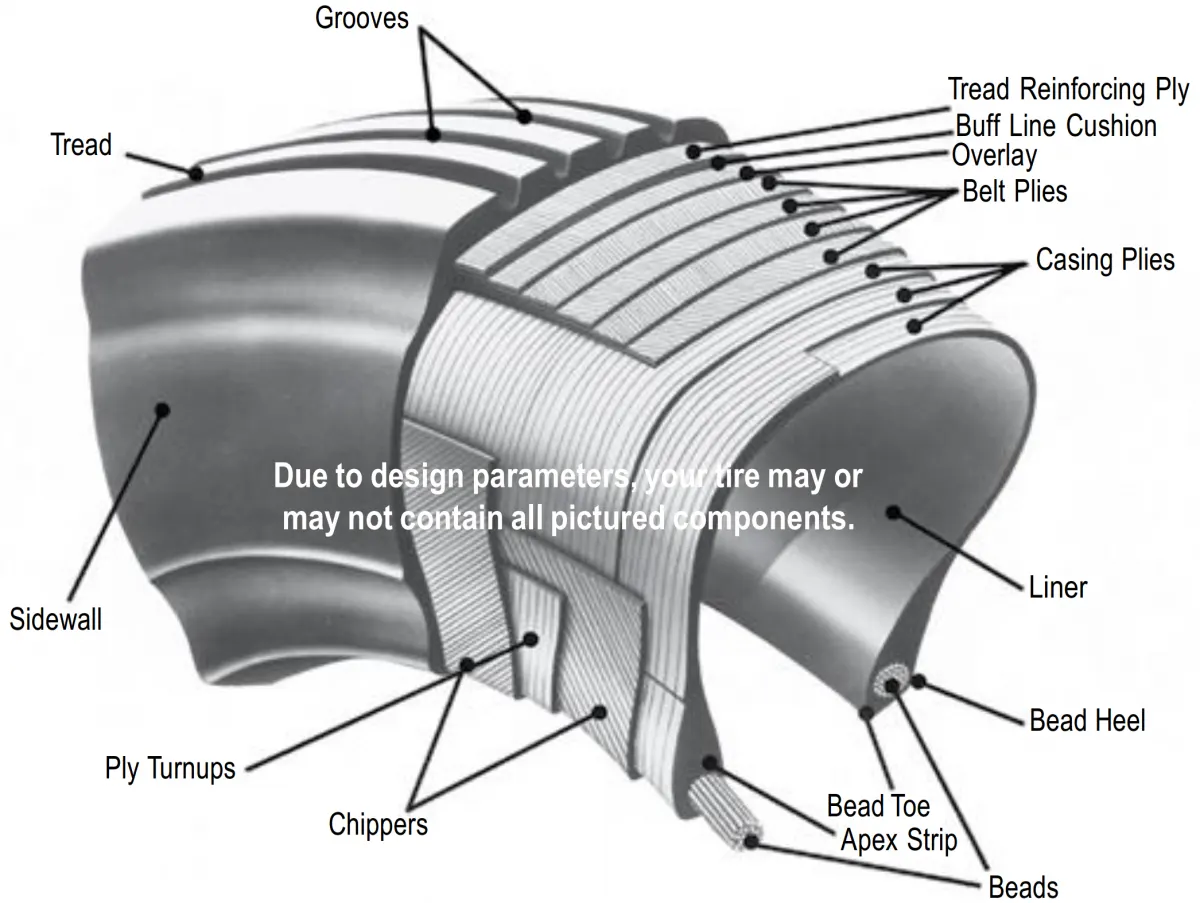
Fig.Composition of a radial ply tyre.
Bias ply tires: These tyres feature a casing which is constructed of alternate layers of rubber-coated ply cords which extend around the beads and are at alternate angles substantially less than 90° to the center line of the tread. The bias ply tyre (illustrated) consists of casing plies running diagonally at approximate right angles to one another. The number of plies and the angles at which they are laid dictate strength and load capacity. High-performance bias aircraft tyres feature inter-tread reinforcing fabric (ITF). This provides additional high-speed stability, reduces tread distortion under load, protects the casing plies from damage and can act as wear indicators on retreadable tyres. Some bias tyres, such as Dunlop's tires for the A400M, feature a kevlar like material to provide for even higher strength. The bias tyre is robust and some examples can be retreaded up to 7 times which lowers the cost of ownership.
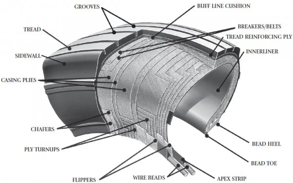
Fig.Composition of a bias ply tyre.
Based on the method for containing the inflation gas the tyres can be:
Tube-type tyres: these require tubes for inflation retention.
Tubeless tyres: these do not require tubes. They are constructed with an innerliner (integral rubber lining that is engineered to prevent the diffusion of the inflation gas into the casing.)
B)Construction:
Breakers: Breakers are reinforcing plies of rubber-coated fabric placed under the buff line cushion to protect casing plies and strengthen and stabilize the tread area. They are considered an integral part of the casing construction.
Tread: The tread is made of rubber mixed with other additives to obtain the desired level of toughness, durability, and resistance to wear. The tread pattern is designed to aircraft operational requirements, with the ribbed tread design used widely due to its good traction under varying runway conditions
Sidewalls: The sidewall is a protective layer of rubber that covers the outer casing ply. It extends from the tread edge to the bead area.
Casing Plies: Alternate layers of rubber-coated fabric (running at opposite angles to one another) provide the strength of the tire.
Chafers: A protective layer of rubber and/or fabric located between the casing plies and wheel to minimize chafing.
Ply Turnups: The casing plies are anchored by wrapping them around the wire beads, thus forming the ply turnups.
Flippers: Layers of rubberized fabric that help anchor the bead wires to the casing and improve the durability of the tire.
Wire Beads: Hoops of high tensile strength steel wire that anchor the casing plies and provide a firm mounting surface on the wheel. The outer edge of the bead that fits against the wheel flange is called the bead heel. The inner bead edge is called the bead toe.
Apex Strip: A wedge of rubber affixed to the top of the bead bundle.
Bead toe: It is the inner edge of the bead.
Bead heel: It is the outer edge of the heel.
Inner Liner: In tubeless tires, the liner is a layer of low permeability rubber that acts as a built-in tube and restricts gas from diffusing into the casing plies. In tube-type tires, a thinner liner is used to prevent tube chafing against the inside ply.
Caroass Plies: Layers of rubber-coated fabric piles which have the cords running from bead to bead. These provide the tire with strength in the sidewall area.
Tread Reinforcing Ply: One or more layers of fabric that strengthens and stabilizes the tread area for high-speed operation. It also serves as a reference for the buffing process when tires are re-treaded.
Buff Line Cushion: The buff line cushion is made of rubber compound to enhance the adhesion between the tread reinforcing ply and the breakers or casing plies. It is of sufficient thickness to allow for the removal of the old tread when the tire is re-treaded.
Tubeless tyres are more advantageous over tube-type. There is no longer the use of tube-type tyre in recent aviation. Aircraft tyres must have an approved speed and load rating and have sufficient clearance when retracted through landing gear to allow for tyre growth. Tyre growth is the increase in the size of the tyre due to centrifugal forces at high speed.
Re-treading: re-treading is methods of restoring a worn tyre by renewing the tread area or by renewing the tread area plus one or both sidewalls. Repairs are included in the tyre re-treading process.
Load Rating: Load rating is the maximum permissible load at a specified inflation pressure.
Ply Rating: Ply Rating is used to identify the maximum recommended load rating and inflation pressure for a specified tyre. It is an index of tyre strength.
Speed Rating: The speed rating is the maximum take-off speed to which the tyre has been tested.
Skid Depth: Skid depth is the distance between the tread surface and the deepest groove as measured in the mould.
Today’s tyres are conductive. Aircraft tyre are manufactured with tread rubber with conducting compounds to permit earthing of static charges. In early days when tyres were not sufficiently conductive, aircraft used to have a conductive strip hanging down from the axle of the landing gear. Upon landing, this strip would be the first part of the aircraft to touch the earth. This discharges any static electricity accumulated on the outer surfaces of the aircraft.
iii)Rolling resistance:Rolling resistance, sometimes called rolling friction or rolling drag, is the force resisting the motion when a body (such as a ball, tire, or wheel) rolls on a surface. It is mainly caused by non-elastic effects; that is, not all the energy needed for deformation (or movement) of the wheel, roadbed, etc., is recovered when the pressure is removed. Two forms of this are hysterises losses and permanent (plastic) deformation of the object or the surface (e.g. soil). Another cause of rolling resistance lies in the slippage between the wheel and the surface, which dissipates energy.
- Energy losses due to heat (hysteresis)
- The forces pushing on the tyre.
A) Energy losses due to heat (hysteresis):As the tyre comes into contact with the road, it changes shape as it is compressed (pushed in a bit). This compression causes parts of the rubber tube and the casing of the tyre to heat up. It also causes the tread on the outside of the tyre to heat up as it comes into contact with the road. A tyre with knobbly tread will have a lot more rolling resistance than a smooth tyre because there will be more rubber being compressed and so there will be more heat.The tyre is a bit like a spring or a rubber band. Some of the energy is stored as the tyre becomes compressed (squeezed in). As the tyre comes back off the road, there is not as much of this stored energy returned because some of it has gone towards making the tyre heat up. This loss of available energy due to heating is called hysteresis. This means there will be less energy available to make the bike go faster.If you feel the temperature of your tyres when you have been biking fast, you will notice this heat. If your tyres are not pumped up hard, there will be even more heat created.The force of rolling resistance does not change at higher speeds. However, because there is a lot more heat being produced at higher speeds, the cyclist uses more power (energy per second) to work against rolling resistance.
B) The forces pushing on the tyre:Rolling resistance happens because the force pushing backwards against the tyre as it comes into contact with the road is bigger than the force pushing forwards as it leaves. As the front part of the tyre touches the road, it takes a lot of force to squeeze in the tyre. This causes a backwards force on the wheel. As the tyre comes back off the road, there is a force pushing forwards on the wheel, but this forwards force is not as great. This is because of internal friction in the tyre. If you could design a tyre that didn’t have internal friction and didn’t heat up, the force at the front section of the tyre contacting the road would be the same size as the force on the back section. This would mean zero rolling resistance, assuming there was no energy loss due to compression of the road surface.
iv)Tyre pressure:An aircraft tire or tyre is designed to withstand extremely heavy loads for short durations. The number of tires required for aircraft increases with the weight of the aircraft, as the weight of the airplane needs to be distributed more evenly. Aircraft tire tread patterns are designed to facilitate stability in high crosswood conditions, to channel water away to prevent hydroplaning, and for braking effect.The pressure generally is vert high in an aircraft tire to reduce the rolling resistance and to withstand the weight. Usually the tyre pressure will be arround 190 to 320 psi based on the type of aircraft. Aircraft tyres are usually inflated with nitrogen to minimize expansion and contraction from extreme changes in ambient temperature and pressure experienced during flight.
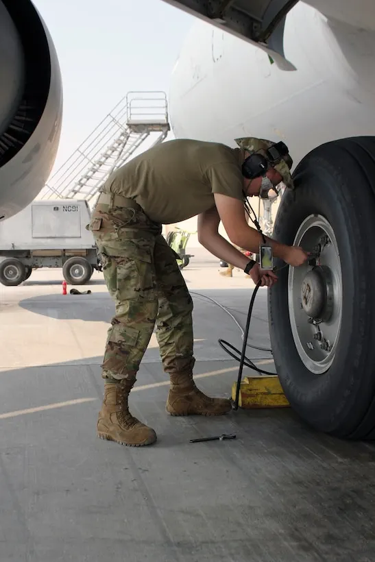
The key to the remarkable durability of an aircraft tire is maximizing the air pressure. With enormous pressures, a very small surface area of the tire is in contact with the runway & hence the friction is less. Also it creates lesser drag & hence the end result is lesser heat generation.
- A typical car tire is pumped at 30–35 psi.
- Typically airliner tires are inflated to 220 psi. Tires on an F-16 fighter are pumped to 320 psi.
- The test pressure of these tires is 800 psi.
For comparison, a typical submarine at its test depth of 350 meters under water can take up only up to 514 psi with more than 1 foot thick hull made up of solid iron. Aircraft tires are amazing when you think about it. The typical airliner tire can handle a 38-ton load. It can meet the ground 500 times before needing a re-tread, a refresh it can take on seven times in its life. A Boeing 777 uses 14 tires, Airbus' A380 carries 22, and the enormous Antonov An-225 demands 32. The key to their remarkable durability is maximizing the air pressure, says Lee Bartholomew, lead test engineer for Michelin Aircraft Tires. The high-flying rubber is typically inflated to 200 psi, roughly six times what you put in an automobile tire, and the tires on an F-16 fighter are pumped to 320 psi.
v)Brake forces when landing:All modern aircraft are fitted with a braking system to assist in slowing and stopping when on the ground. Brakes are used not only to decelerate during a landing run, but also to hold the aircraft during an engine run-up, and in some cases to steer the aircraft through differential braking. Brakes are fitted to the main landing gear but not generally to the nose or tail wheel. Stopping an aircraft landing at 180-200 mph requires a lot of braking force. To do this, the aircraft has brake unit on each of the wheels on the main gear assembly. On landing, pilots should use aerodynamic braking by applying extra back-pressure on the stick or yoke. Extreme caution should be used when applying brakes at any significant speed, and only when the end of the runway is quickly approaching. Never step on the brakes to make a runway exit. Applying the brakes at too high a speed could burn the tires, wear out the brakes, or result in a ground loop or swerve.
Aircraft braking systems include:
i)Aircraft Disc Brake: In the landing gear it is used to brake the wheels while touching the ground. These brakes are operated hydraulically. In most modern aircraft they are activated by the top section of the rudder pedals ("toe brakes"). In some older aircraft the bottom section is used instead ("heel brakes"). Levers are used in a few aircraft. Most aircraft are capable of differential braking.
ii)Thrust Reverse: that allow thrust from the engines to be used to slow the aircraft.
iii)Air Brake: It is dedicated flight control surface, that work by increasing drag.
iv)Drogue Parachute: It is used by several former and current military and civilian aircraft (examples include the American B-52 and the soviet Tu-134 and Tu-144).
Brake System Enhancement:Anti-skid, auto-brake, brake temperature indicators and brake fans are all systems which enhance the performance of the aircraft brakes.
Anti-skid system:The anti-skid system, through various mechanisms, compares the speed of the aircraft with the rotational speed of each main wheel. If the speed of any wheel is too slow for the existing aircraft speed, the brake on that wheel (or wheels) is released momentarily to allow the wheel speed to increase and prevent the wheel from skidding. The system is fully automatic and is active from immediately after initial wheel spin up on landing (during which time brake activation might (or might not) be inhibited) down to a design limited minimum speed; usually about 15 knots. Anti-skid systems are designed to minimise aquaplanning and the potential tyre damage which can occur when a wheel is locked or rotating at a speed which does not correspond to the speed of the aircraft. Anti-skid removes the possibility of reverted rubber skids caused by locked wheels. An anti-skid system also greatly improves stopping distance on substandard surfaces such as gravel or grass and is particularly effective on surfaces contaminated with frozen contaminants such as ice or slush by ensuring maximum effective breaking.
Auto-brake systems:Auto-brake systems can be used on takeoff where they will provide maximum braking in the event of a rejected take-off and on landing where they will provide a scheduled rate of deceleration (dependent upon the auto-brake level selected) using only a single brake application. These features combine to optimize the brake usage with respect to the requirement and to minimize brake wear.
Part B:
Que.6: A. With necessary assumptions, calculate the force and power required to push / pull an aircraft by a towing vehicle.
B. Develop the model for the calculated force and power using Simulink.
Ans:
A)With necessary assumptions, calculate the force and power required to push/pull an aircraft by a towing vehicle.
To push back the aircraft from the terminal gate a towing vehicle is required. Towing vehicle does not require much horsepower but they need lots of torque to push or pull the aircraft.For calculating the force and power required by the towing vehicle to push or pull the aircraft. The following forces are considered.
- Rolling resistance force
- Acceleration force
- Aerodynamic drag force
i) Aircraft Calculations:
Assumptions,
Mass of the aircraft (ma) = 48500kg
Coefficient of rolling resistance (μr) = 0.03
Acceleration due to gravity (g) = 9.81ms-2
Frontal area of an aircraft (A) = 85m2
Final velocity of the aircraft (vf) = 3m/s
Initial velocity of the aircraft (ui) = 0m/s
Coefficient of drag of an aircraft (cd) = 0.15
Density of air (ρ) = 1.225 kg/m3
Acceleration time of the aircraft (ta) = 10 seconds.
a)Rolling Resistance force calculations:
Rolling resistance is the force that resists the motion when the body rolls on the surface.
It is represented by the following equation:
Frr = μr m g
Where ,
Frr = rolling resistance force (N)
μr = coefficient of rolling resistance
m = Total mass of the vehicle (kg)
g = Acceleration due to gravity (m/s2)
Frr = μr m g
∴Frr = 0.03 x 48500 x 9.81
∴Frr (a) = 14274N.
The rolling resistance force between aircraft wheels and tarmac road is 14274N.
b)Acceleration Force Calculations:
Acceleration force is defined as the rate of change of velocity with respect to time.
It is represented by the formula:
F= m x a
m = mass
a = acceleration
F= m x a
F= m x (vf – vi) / t
∴F= 48500 x ( 3 – 0) / 10
∴F= 48500 x 3 / 10
∴F= 4850 x 3
F(a)= 14550 Newton.
The acceleration force of the aircraft is 14550 N.
c)Aerodynamic Drag Force Calulations:
Aerodynamic drag force is the drag force that acts apposite to the relative motion of any object moving with respect to a surrounding fluid.
It is represented by the formula:
Fd = ½ x ρ x A x cd x v2
Where,
Ρ = Density of air (kg/m3)
A = Frontal area ( m 2)
cd = Drag coefficient
v2 = Velocity (m/s)
Fd = ½ x ρ x A x cd x v2
∴Fd = ½ x 1.225 x 85 x 0.15 x 32
∴Fd (a) = 70.284 Newton.
The aerodynamic drag force experienced by the aircraft when it moves on the ground is 70.284 N.
ii) Towing Vehicle Calculation:
Assumptions,
Mass of the Towing vehicle (ma) = 8000kg
Coefficient of rolling resistance (μr) = 0.013
Acceleration due to gravity (g) = 9.81ms-2
Frontal area of the Towing vehicle (A) = 8m2
Final velocity of the Towing vehicle (vf) = 3m/s
Initial velocity of the Towing vehicle (ui) = 0m/s
Coefficient of drag of the towing vehicle (cd) = 0.60
Density of air (ρ) = 1.225 kg/m
Acceleration time of the towing vehicle (ta) = 10 seconds.
a)Rolling Resistance force calculations:
Frr = μr m g
∴Frr = 0.013 X 8000 X 9.81
∴Frr (t) = 1020.24 Newton.
The rolling resistance force between the towing vehicle wheels and tarmac road is 1020.24 N.
b)Acceleration Force Calculations:
F= m x a
F= m x (vf – vi) / t
∴F= 8000 x ( 3 – 0) / 10
∴F= 8000 x 3 / 10
∴F= 800 x 3
∴F(t) = 2400 Newton.
The acceleration force of the Towing vehicle is 2400 N.
c)Aerodynamic Drag Force Calulations:
Fd = ½ x ρ x A x cd x v2
∴Fd = ½ x 1.225 x 8 x 0.60 x 32
∴Fd (t)= 26.46 Newton.
The aerodynamic drag force experienced by the Towing vehicle when it moves on the ground is 26.46 N.
To calculate the total tractive force required, we need to add all the forces obtained,
iii)Total tractive force:
FT = Frr (a) + F(a) + Fd (a) + Frr (t) + F(t) + Fd (t)
∴FT = 14274+14550+70.284+1020.24+2400+26.46
∴FT = 32340.984 Newton
∴FT = 32.340984 Kilo-Newton.
iv) Power required to push/pull an aircraft by a towing vehicle:
P = FT * V
∴P = 32340.984*3
∴P = 97022.952 Watt.
∴P = 97.022952Kilo-Watt.
The force and power required to push/pull an aircraft by a towing vehicle is 32.340984 Kilo-Newton & 97.022952Kilo-Watt respectively.
B)Develop the model for the calculated force and power using Simulink:
M-Script File:
clc
clear
close
%Aircraft Calculations:
ma= 48500;                     %Mass of the aircraft in Kg.
Rra= 0.03;                     %Coefficient of rolling resistance(μrr).
g= 9.81;                       %Acceleration due to gravity in ms-2.
Aa= 85;                        %Frontal area of an aircraft in m2.
vfa= 3;                        %Final velocity of the aircraft in m/s.
uia= 0;                        %Initial velocity of the aircraft in m/s.
cda= 0.15;                     %Coefficient of drag of an aircraft.
rhoa= 1.225;                   %Density of air (ρ) in kg/m3.
taa= 10;                       %Acceleration time of the aircraft in seconds.
Frra= Rra*ma*g;                %Rolling Resistance force of an aircraft in Newton.
Faa= ma*(vfa-uia)/taa;         %Acceleration force of an aircraft in Newton.
Fda=0.5*rhoa*Aa*cda*vfa^2;      %Aerodynamic drag force experienced by the aircraft in Newton.
%Towing Vehicle Calculation:
mt= 8000;                      %Mass of the Towing vehicle in kg.
Rrt = 0.013;                   %Coefficient of rolling resistance(μrr).
At= 8;                         %Frontal area of the Towing vehicle in m2.
vft = 3;                       %Final velocity of the Towing vehicle in m/s.
uit = 0;                       %Initial velocity of the Towing vehicle in m/s.
cdt = 0.60;                    %Coefficient of drag of the towing vehicle.
rhot = 1.225;                  %Density of air (ρ) in kg/m.
tat= 10;                       %Acceleration time of the towing vehicle seconds.
Frrt=Rrt*mt*g;                 %Rolling Resistance force of a towing vehicle in Newton.
Fat= mt*(vft-uit)/tat;         %Acceleration force of a towing vehicle in Newton.
Fdt=0.5*rhot*At*cdt*vft^2;     %Aerodynamic drag force experienced by towing vehicle in Newton.
%The force and power required to push/pull an aircraft by a towing vehicle.
FT=Frra+Faa+Fda+Frrt+Fat+Fdt;  %Total tractive force in Newton.
P=FT*vft;                      %Power required to push/pull the vehicle in watt.
Simulink model:
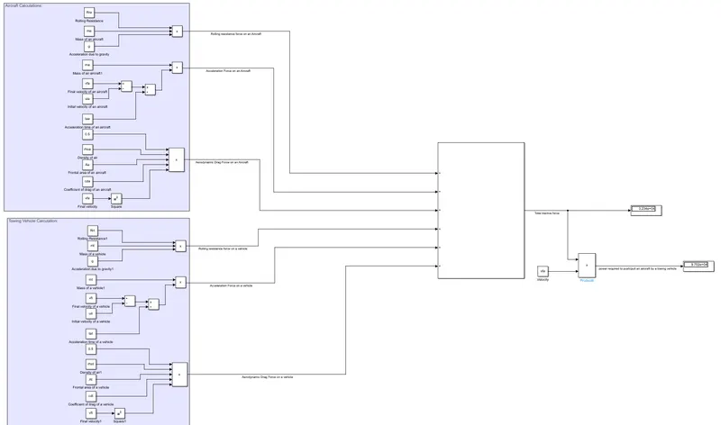
Model Explaination:
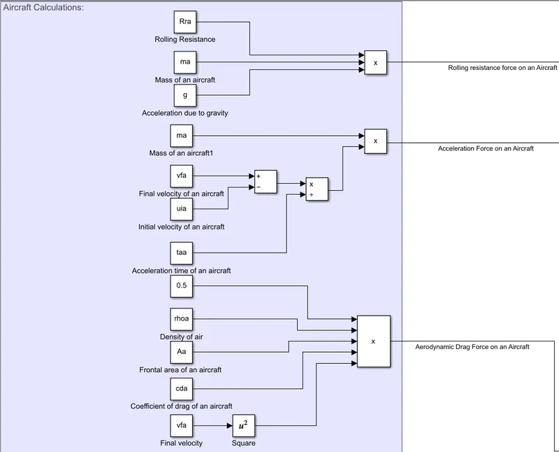
- From the above figure for the creation of the Simulink model, firstly we consider all the forces acting on the aircraft such as rolling resistance force, aerodynamic drag force and acceleration force.
- The values are (assumed in m-script) taken from base workspace for mass of the aircraft, coefficient of rolling resistance, frontal area, drag coefficient and velocity and substituted in the respective formulas for rolling resistance force, drag coefficient force and acceleration force.
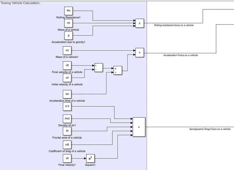
- Similarly for the above figure the forces are calculated for the towing vehicle the values are assumed & taken from base workspace and substituted in the respective formulas for rolling resistance force, aerodynamic drag and acceleration force.
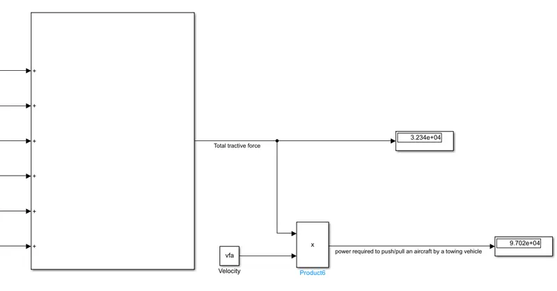
- Finally, all the forces are added to obtain the total tractive force and the power is obtained by multiplying the total tractive force with the velocity.
- The simulation is run and the both the force and the power values are displayed using the display block.
Que.7: A. Design an electric powertrain with type of motor, it’s power rating, and energy requirement to fulfill aircraft towing application in Simulink. Estimate the duty cycle range to control the aircraft speed from zero to highest. Make all required assumptions. Prepare a table of assumed parameters. Draw a block diagram of powertrain.
(Hint :DC7 Block)
B. Also, Design the parameters in excel sheet.
Ans: From above calculation the total power required to push or pull the aircraft by the towing vehicle is 97.022952KW and the total tractive force is 32340.984N. To calculate the torque required by the Towing vehicle the following parameters are assumed as shown above:
Let us assume,
The Radius of the Tyre for the Tug = 25inches =0.635m
Gear ratio = 8
Transmission Effeciency (ηt) =87%
Motor Efficiency (ηm)=95%
then,
Torque required for the wheels (Tw)=Total Force *Radius in meters
=32.34*0.635
= 20.54KNm
Motor Torque= Wheel torque/(Gear ratio*ηt)
= 20.54/ (8*0.87)
= 2.88KNm
For ηm =95%, The required motor Torque (Tm)= 2.88/0.95 = 3.0318 KNm.
Similarly, The total power required by the motor considering all the efficiencies(Pt) =97.022 /(0.87*0.95)=117.38KW
Let us assume,
Operational time of the Towing for one cycle =.25 Hour(15min)
Required Energy(E) for towing application based on the assumed time, that is E = P * t
∴E = 117.38(kw)* (.25hr)
∴E = 29.34 KWh.
So, the battery pack provides 29.34 KWh of energy to the vehicle.
To design the electric power train of the towing vehicle a motor is selected based on its power rating and the battery required based on energy requirement and duty cycle range to control the aircraft speed from zero to highest.
Motor Selection:
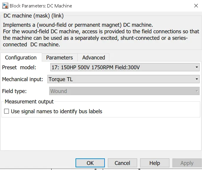
The motor should be selected according to required power rating of 117.38 KW and torque of 3.0318 KNm. we have selected electric motor which has power output of 200 KW and torque at full load is 3000Nm that satisfies the power output and torque needed for the vehicle.
Motor Specifications:
Output power=150 KW, 200 hp
Full load speed= 1400 rpm
Full load Efficiency=94.5%
Full load current=216A
Full load Torque=3000Nm
Rated voltage=690V/50 Hz.
Duty Cycle:The rated (supplied/input) voltage is 690V and the current is assumed to be 216A. So, the input power of the motor is calculated as product of voltage and current.
Pi =V*I
∴Pi = 690 *216
∴Pi = 149040W
∴Pi = 149.040KW
To calculate the duty cycle we divide output power to input power,
Duty Cycle=Po / Pi
∴Duty Cycle= 117.38/ 149.040
∴Duty Cycle= 0.7876
∴Duty Cycle= 78.76%
Powertrain Design (DC7 Block):
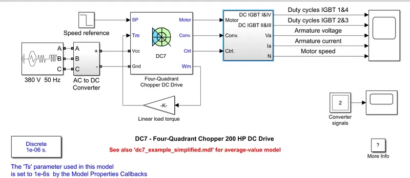
Results/Observation:
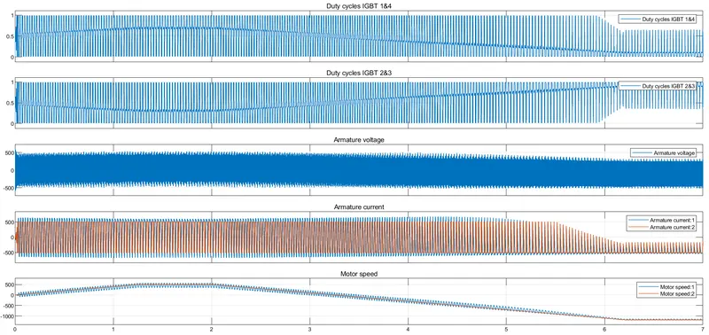
It is observed that above plot that motor attain high speed at appprox. 2 sec & afterward it slows down & at approx 3 sec it becomes zero & reverse the speed afterward.
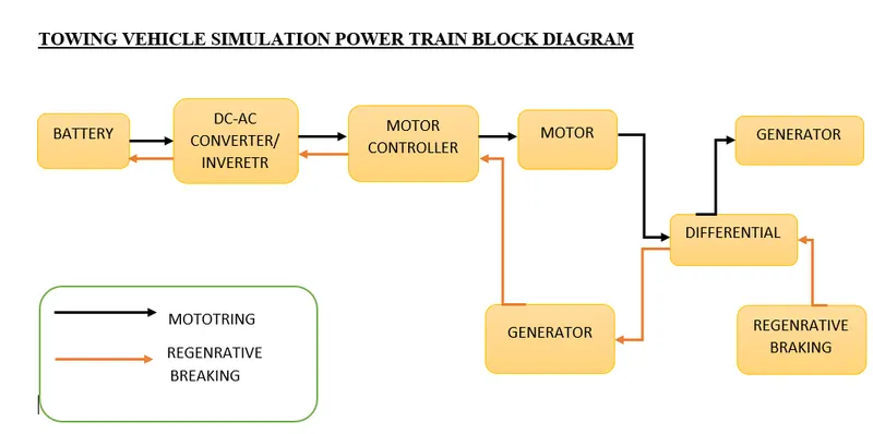
Block diagram of powertrain:
Towing Vehicle Simulation Powertrain block diagram:
B)Design the parameters in excel sheet.
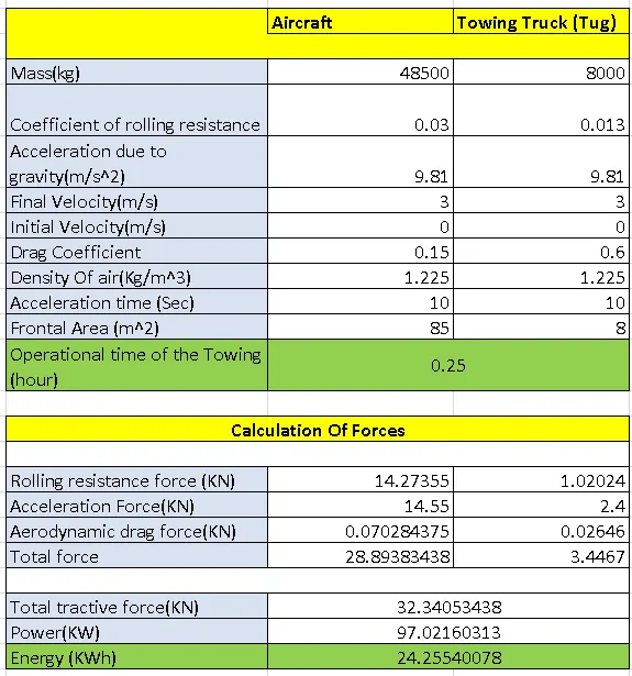
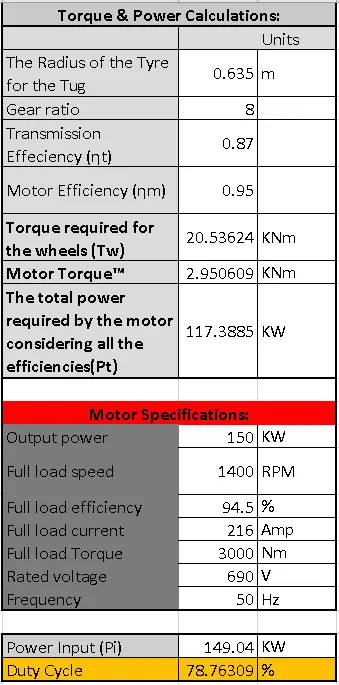
Results:
|
Required torque output of the motor |
3031.8 Nm |
|
Input power of the motor |
149.040KW |
|
Duty cycle range |
78.76% |
|
Energy required from the batteries |
29.34KWh |
Conclusions:The reference Aircraft taken here is the Heavy Aircraft build and so our designed towing tractor is a heavy duty operational vehicle.The power requirements are calculated for the particular load to be pushed/pulled and to achieve this power at the motor output, the motor type and its voltage at the terminals are discussed.
Then the power converters are used to upscale the battery armature voltage to thr desired high voltage value so that the motor may spin at full power and required torque can be achieved using a Bidirectional DC-DC Converter. Finally the speed control of the vehicle is done with switching techniques where the Duty Cycle adjustment can change the motor speed from the minimum to maximum.