Project-1: Powertrain for aircraft in runways
Part A:
1. Search and list out the total weight of various types of aircrafts.
2. Is there any difference between ground speed and air speed?
3. Why is it not recommended to use aircraft engine power to move it on the ground at Airport?
4. How an aircraft is pushed to runway when its ready to take off?
5. Learn about take off power, tyre design, rolling resistance, tyre pressure, brake forces when landing.
ANSWER:
1.
Manufacturer's empty weight (MEW)
Also called Manufacturer's Weight Empty (MWE) or Licensed Empty Weight
It is the weight of the aircraft "as built" and includes the weight of the structure, power plant, furnishings, installations, systems and other equipment that are considered an integral part of an aircraft.
This excludes any baggage, passengers, or usable fuel.
The different terms represent different weights or masses1. For each flight, the weights are taken into account for several reasons.
A brief description about these is below:
Zero-fuel weight (ZFW)
This is the total weight of the airplane and all its contents (including unusable fuel), but excluding the total weight of the usable fuel on board.
As a flight progresses and fuel is consumed, the total weight of the airplane reduces, but the ZFW remains constant.
Maximum zero fuel weight (MZFW) is the maximum weight allowed before usable fuel and other specified usable agents (engine injection fluid, and other consumable propulsion agents) are loaded.
Operating empty weight (OEW) (Roughly equivalent to basic empty weight on light aircraft)
It is the basic weight of an aircraft including the crew, all fluids necessary for operation such as engine oil, engine coolant, water, unusable fuel and all operator items and equipment required for flight but excluding usable fuel and the payload.
It is the carrying capacity of an aircraft. It includes cargo, people, extra fuel. In the case of a commercial airliner, it may refer only to revenue-generating cargo or paying passengers.
Maximum takeoff weight (MTOW)
This is the maximum weight at which the pilot of the aircraft is allowed to attempt to take off3.
Regulated takeoff weight (RTOW)
Depending on different factors (e.g. flap setting, altitude, air temperature, length of runway), RTOW or maximum permissible takeoff weight varies for each takeoff. It can never be higher than MTOW. More information is on this answer.
Maximum landing weight (MLW)
This maximum weight at which an aircraft is permitted to land.
Maximum ramp weight (MRW)
also called maximum taxi weight (MTW)
It is the maximum weight authorized for maneuvering (taxiing or towing) an aircraft on the ground.
It is the total aircraft weight at any moment during the flight or ground operation. This decreases during flight due to fuel and oil consumption.
An average airplane weighs around 90,000 pounds (41,000 kilos) empty weight, which means the weight of the airplane when its fuel tanks are empty and there are no people or luggage on board. This example is for a B-737-800 aircraft which is considered a medium-sized commercial jet airliner.
Classifications Of Aircraft:
In most common terms, there are two types of classifications for aircrafts. One is lighter than air aircrafts, known as aerostats, and the other is heavier than air aircrafts, called aerodynes.
Aerodynes (Heavier Than Air): is much higher in weight and size. They push the gas or air downwards, which reaction helps to make aircraft upwards.
Since these are dynamic through movements in the air, they are called aerodynes.
Aerostats (Lighter Than Air): Aerostats or lighter than air aircrafts are very more lightweight in weight.
these types of light aircraft generally use buoyancy like ships, which helps them float in the air. Low-density gas such as hydrogen, helium, or hot air balloons is used to fill in the aircraft.
This low-density gas is lighter than air, hence the name. The most common types of aerostats known to us are hot air balloons and sky lanterns.
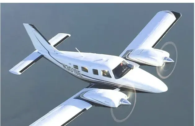
Multi-Engine Piston:
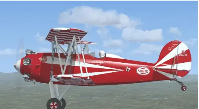
Biplanes:
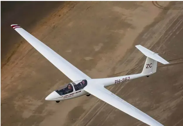
Gliders:
You can expect to add 84,000 pounds (38,000 kilos) of fuel, passengers, and baggage to that number to get a maximum takeoff weight of 174,000lbs (79,000 kilos).
- Cessna 172 – Used by many as initial training aircraft (27 feet long) – 1450lbs empty weight, 2450lbs max weight.
- Citation Jet M2 – (42 feet long) – 3170.61066 kgm empty weight, 4853.43835kg max weight.
- Boeing 767-300 – (185 feet long) – 88450.5 kgm empty weight, 400,000 max weight
- Boeing 787-800 – (186 feet long) – 119975.182 kgm empty weight, 227930.166 kgm max weight
- Boeing 777-300 – (242 feet long) – 160571.6kgm empty weight, 299370.964 kgm max weight
- Boeing 747-400 – (232 feet long) – 184612.094 kgm empty weight, 412769.056 kgm max weight
- Airbus A320 – (123 feet long) – 37194.5743 kgm empty weight, 77110.7028 kgm max weight
- Airbus A330 – (210 feet long) – 124511.105 kgm empty weight, 229971.331 kgm max weight.
-
The average medium-sized airliner weighs around 90,000lbs.
- Is there any difference between ground speed and air speed?
True Airspeed (TAS) is the indicated Airspeed corrected for nonstandard pressure and temperature. It reflects the actual speed of the relative airflow over the aircraft. In still air, the TAS is equal to the groundspeed. Groundspeed is the speed the aircraft is crossing over the ground at.
The speed of that wind can be measured using a tool called an anemometer. An anemometer looks like a weather vane, but instead of measuring which direction the wind is blowing with pointers, it has four cups so that it can more accurately measure wind speed.
ground speed in aviation :Ground speed is the horizontal speed of an aircraft relative to the ground. An airspeed indicator indicates the aircraft's speed relative to the air mass. The air mass may be moving over the ground due to wind, and therefore some additional means to provide position over the ground is required.
Ground speed can be determined by the vector sum of the aircraft's true airspeed and the current wind speed and direction; a headwind subtracts from the ground speed, while a tailwind adds to it. Winds at other angles to the heading will have components of either headwind or tailwind as well as a crosswind component.
Airspeed vs. Ground Speed
Airspeed is the vector difference between the ground speed and the wind speed. On a perfectly still day, the airspeed is equal to the ground speed. But if the wind is- blowing in the same direction that the aircraft is moving, the airspeed will be less than the ground speed.
- true airspeed is simply the speed at which an aircraft is moving relative to the air it is flying in. As such, it’s also the speed at which the air is flowing around the aircraft’s wings.
- Ground speed, on the other hand, is the aircraft’s speed relative to the ground. One thing that should be noted here is that it’s its horizontal rather than vertical speed – an aircraft climbing completely vertically would have a ground speed of zero.
- In other words, while airspeed is what determines whether there is enough airflow around an aircraft to make it fly, ground speed is what determines how fast an aircraft will get to its destination.
- While ground speed is the airplane’s speed relative to the surface of the Earth,
- airspeed – at least true airspeed – is its speed relative to the air it is flying in
Why is it not recommended to use aircraft engine power to move it on the ground at Airport?
- Some work is being done on self-contained electric-powered ground propulsion; one major player in this area is a company called WheelTug. They use high-torque motors and the aircraft APU to allow the aircraft to move itself without starting its engines or requiring a tug to be connected and disconnected.
- An aircraft engine has multiple functions. It is used for generating electricity to power the various systems in an aircraft.
- It also draws in air that’s needed inside the cabin. If the engines are switched off then the pilot has to turn on the APU or Auxiliary Power Unit — a generator running on the same jet fuel, inside the tail section of the plane. When an aircraft is parked at the gate, it draws its power from the ground power units. It also takes at least 3 - 5 minutes to power up the engines. That is a lot of time in an over crowded airport like Mumbai — which has only one functional runway. The waiting time for clearance is uncertain.
There are two main types of take off procedures. One is called a static take off and the other is known as a rolling take off.
- In a static take off, the pilot keeps the toe brake on and applies an intermediate or in some aircraft full take off power. Once the power set as required, the brakes are released and the aircraft is allowed to roll on the runway for the take off. In a rolling take off, the brakes are released, the engines stabilised and full power is set while you allow the airplane to roll on the runway,
- Motor-gliders were designed to be flown with the engine off with either a retractable engine/prop unit, similar to retractable landing gear, or a conventional prop that can be feathered or folded during glide.
- In either case, the airflow is blocked to the engine when shut off not only to prevent overcooling the engine, but also because the drag associated with engine cooling degrades the sailplane’s glide performance.
3. How an aircraft is pushed to runway when its ready to take off? rolling resistance, tyre pressure, brake forces when landing?
So when the heavy aircraft once ready to take-off, with all the three wheels on ground, the aircraft start gaining speed by increasing thrust, while soon the Captain (sooner the minimum take-off speed is achieved) pushes the stick (located some times in between the seats) to the tail or behind, results an upward movement.
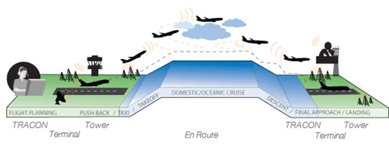
- the aircraft’s nose points to the gate and it is pushed back onto the taxiway by an airport tug, as it is incapable of reversing itself. Once on the taxiway, it taxis slowly towards the runway. Extensive planning is needed before an aircraft can take off.
- the plane take-off begins. The engines howl up and the aircraft lifts slightly at the front. In most cases, the engine power is not fully utilized. In order to relieve the high-tech engines, the power peaks are reduced by a precisely calculated value. The existing track length should be used as efficiently as possible. This not only reduces the service life of the engines, but also other wear, noise and emissions.
- In order to take off, a certain speed must already be reached on the runway, as this is the only way to overcome gravity so that the aircraft can take off. Commercial airliners accelerate to a proud 250 to 345 km/h.
- The elevators cause the aircraft to rotate around its transverse axis. The nose of the aircraft is lifted and the nose gear lifts off. The point until which the pilot can abort the take-off is called V1. If he would take out the throttle until then, the glider would automatically perform a kind of “emergency braking”. After exceeding V1 the aircraft has to take off.
- The tires of the airplanes are filled with nitrogen and only roll with it. This means that they are not driven by themselves, as in a car. The aerodynamic lift on the wings is achieved by increasing the angle of attack. First the nose wheel lifts off, then the rear wheels. The pull you can feel at this moment is caused by the gravitational force and is already over after a few seconds.
- Finally the pilot takes off and retracts the landing gear. For 15 to 20 minutes the airplane is in the climb flight (Climb), before it changes into the cruise flight (Cruising).
Take off power
Power take-off (PTO) transfers the mechanical power of the engine over to another piece of the equipment. This allows for the power to move throughout the equipment to transmit energy even if it doesn’t have a motor or engine itself.
Rotating power becomes hydraulic power with a PTO system because the gear from the power take-off unit connects to the flywheel or crankshaft in the engine. Turning the wheel or crankshaft builds up a charge in a hydraulic pump.
PTO Torque and Horsepower Requirements
Speed and rotation requirements of a PTO are among the most important specifications in the list above, with speed being necessary for calculating torque. The torque and horsepower requirements of the driven component are critical for optimal performance.
In most cases, the owner’s manual of the driven component will provide this information, but calculation of these requirements, if necessary, is relatively simple using two basic formulas.
- HP = GPM x PSI ÷ 1714
HP (horsepower) = GPM (pump flow in gallons/minute) x PSI (pump pressure required pounds/inch) ÷ 1714 (conversion factor to yield HHP or hydraulic horsepower). This formula provides the horsepower requirement for the driven component, used in calculating the torque requirement.
- T = HP × 5252 ÷ RPM
T (torque) = HP x 5252 (the rpm rate where both torque and horsepower intersect) ÷ RPM (RPM rate of the drive shaft of the driven component).
4. Design and Construction of Aircraft tyre
Tire Construction
An aircraft tire is constructed for the purpose it serves. Unlike an automobile or truck tire, it does not have to carry a load for a long period of continuous operation. However, an aircraft tire must absorb the high impact loads of landing and be able to operate at high speeds even if only for a short time. The deflection built into an aircraft tire is more than twice that of an automobile tire. This enables it to handle the forces during landings without being damaged. Only tires designed for an aircraft as specified by the manufacturer should be used.
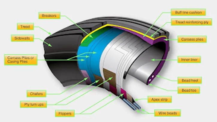
It is useful to the understanding of tire construction to identify the various components of a tire and the functions contributed to the overall characteristics of a tire. Refer to Figure for tire nomenclature used in this discussion.
-
Tread
- The tread is the crown area of the tire designed to come in contact with the ground. It is a rubber compound formulated to resist wear, abrasion, cutting, and cracking.
- It also is made to resist heat build-up.
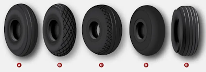
- Most modern aircraft tire tread is formed with circumferential grooves that create tire ribs. The grooves provide cooling and help channel water from under the tire in wet conditions to increase adhesion to the ground surface.
- Tires designed for aircraft frequently operated from unpaved surfaces may have some type of cross-tread pattern.
- Older aircraft without brakes or brakes designed only to aid in taxi may not have any grooves in the tread.
- An all-weather tread may be found on some aircraft tires. This tread has typical circumferential ribs in the center of the tire with a diamond patterned cross tread at the edge of the tire.
- The tread is designed to stabilize the aircraft on the operating surface and wears with use. Many aircraft tires are designed with protective undertread layers as described above. Extra tread reinforcement is sometimes accomplished with breakers.
- These are layers of nylon cord fabric under the tread that strengthen the tread while protecting the carcass plies.
- Tires with reinforced tread are often designed to be re-treaded and used again once the tread has worn beyond limits.
Sidewall
- The sidewall of an aircraft tire is a layer of rubber designed to protect the carcass plies.
- It may contain compounds designed to resist the negative effects of ozone on the tire. It also is the area where information about the tire is contained.
- The tire sidewall imparts little strength to the cord body.
- Its main function is protection.
The inner sidewall of a tire is covered by the tire inner liner. A tube-type tire has a thin rubber liner adhered to the inner surface to prevent the tube from chafing on the carcass plies. Tubeless tires are lined with a thicker, less permeable rubber. This replaces the tube and contains the nitrogen or inflation air within the tire and keeps from seeping through the carcass plies.
The inner liner does not contain 100 percent of the inflation gas. Small amounts of nitrogen or air seep through the liner into the carcass plies. This seepage is released through vent holes in the lower outer sidewall of the tires. These are typically marked with a green or white dot of paint and must be kept unobstructed. Gas trapped in the plies could expand with temperature changes and cause separation of the plies, thus weakening the tire leading to tire failure. Tube-type tires also have seepage holes in the sidewall to allow air trapped between the tube and the tire to escape. [Figure 8]

A sidewall vent marked by a colored dot must be kept free from obstruction to allow trapped air or nitrogen to escape from the carcass plies of the tire
Carcass Plies
- Carcass plies, or casing plies as they are sometimes called, are used to form the tire.
- Each ply consists of fabric, usually nylon, sandwiched between two layers of rubber. The plies are applied in layers to give the tire strength and form the carcass body of the tire.
- The ends of each ply are anchored by wrapping them around the bead on both sides of the tire to form the ply turn-ups.
- the angle of the fiber in the ply is manipulated to create a bias tire or radial tire as desired. Typically, radial tires require fewer plies than bias tires.
Once the plies are in place, bias tires and radial tires each have their own type of protective layers on top of the plies but under the tread of the running surface of the tire.
On bias tires, these single or multiple layers of nylon and rubbers are called tread reinforcing plies.
On radial tires, an undertread and a protector ply do the same job. These additional plies stabilize and strengthen the crown area of the tire.
They reduce tread distortion under load and increase stability of the tire at high speeds.
The reinforcing plies and protector plies also help resist puncture and cutting while protecting the carcass body of the tire.
An aircraft tyre is designed to withstand extremely heavy loads while landing, take off, taxing, and parking.
The number of wheels required for aircraft increases with the weight of the aircraft, as the weight of the aeroplane needs to be distributed more evenly.
Carcass plies are used to form the tire. They are sometimes called casing plies. An aircraft tyre is constructed for the purpose it serves.
- They support the weight of an aircraft while it is on the ground.
- It also provides the necessary traction for braking and stopping of an aeroplane.
- Tyre also helps to absorb the shock of landing and provide cushioning the roughness of takeoff, roll-out, and taxi operations.
Retreading – Retreading is methods of restoring a worn tyre by renewing the tread area or by renewing the tread area plus one or both sidewalls. Repairs are included in the tyre retreading process.
Load Rating – Load rating is the maximum permissible load at a specified inflation pressure.
Ply Rating – Ply Rating is used to identify the maximum recommended load rating and inflation pressure for a specified tyre. It is an index of tyre strength.
Speed Rating – The speed rating is the maximum takeoff speed to which the tyre has been tested.
Skid Depth – Skid depth is the distance between the tread surface and the deepest groove as measured in the mould.
Aircraft tyres must have an approved speed and load rating and have sufficient clearance when retracted through landing gear to allow for tyre growth. Tyre growth is the increase in the size of the tyre due to centrifugal forces at high speed.
Tire Pressure
High inflation pressure and high deflection rates – 2.5 times greater than a car tire – allow relatively small tires to support the high loads of an aircraft. Because aircraft tires operate at such high extremes of pressure, load, and speed, their care and service is critically important
-
Aircraft tires are not the same as passenger car or truck tires. As a result, their care and service requirements differ.
-
Because aircraft tires operate at such high extremes of pressure, load, and speed, their care and service is critically important. The most important action an operator can take to prevent tire-related events is to maintain proper tire inflation pressure. Failure to keep aircraft tires properly inflated can lead to very serious consequences. The most serious of these is the structural failure of the tire. If the tire operates underinflated or overdeflected/overloaded, the nylon cords which form the structure of the tire go in and out of compression as the tire rotates. This weakens the cords – much like a paperclip which is bent back and forth – until eventually the cords break. If enough cords break, the entire structure will eventually fail
Aircraft brakes :
The most common type of brake used on aircraft is the disc brake. Disc brakes function by exploiting friction between rotating and stationary discs inside the brake.
Upon receiving a command signal to brake — from the pilot depressing a foot pedal or from the autobrake system — actuators in the brake move a piston to squeeze the discs together, generating a frictional force that slows the rotation of the wheel. The friction between the discs generates heat as the aircraft’s kinetic energy is converted to heat energy. In this function, the brakes act as a heat sink, absorbing tremendous amounts of heat as the aircraft sheds kinetic energy. During RTO stops, the temperature of carbon disc brakes can exceed 1,800° C.
the world’s biggest passenger airplane — performing an RTO at V1. The maximum take-off weight of an A380 is 575,000 kg (1,267,658 lb) and its maximum V1 is around 170 knots (about 195 mph or 87 m/s). A rough estimate for the maximum energy that the A380’s 16 brakes need to dissipate during RTO can be obtained by calculating the kinetic energy of the aircraft (neglecting the effects of thrust reversers, air brakes, tailwinds, headwinds and runway slope).
Since kinetic energy (KE) is a function of mass (m) and velocity (v) according to the equation:
KE = ½mv2
The kinetic energy of the A380 during RTO is calculated as follows:
KE = 0.5 * 575,000 kg * (87.4556 m/s)2 = 2.2 x 10⁹ J = 2.2 GJ
Part B:
6. A. With necessary assumptions, calculate the force and power required to push / pull an aircraft by a towing vehicle.
B. Develop the model for the calculated force and power using Simulink.
7. A. Design an electric powertrain with type of motor, it’s power rating, and energy requirement to fulfill aircraft towing application in Simulink. Estimate the duty cycle range to control the aircraft speed from zero to highest. Make all required assumptions. Prepare a table of assumed parameters. Draw a block diagram of powertrain.
(Hint :DC7 Block)
B. Also, Design the parameters in excel sheet.
-
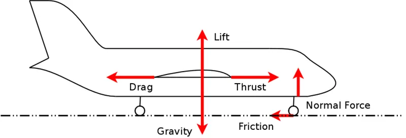
The force to move an airplane on an absolute flat runway with no wind at constant low speed is equal to the rolling resistance between the plane and the tarmac.
The rolling resistance for the air plane can be calculated as
Fr = c mr ag (1)
where
Fr = rolling resistance (N, lbf)
c = rolling resistance coefficient
mr = rolling mass (kg, lbm)
ag = acceleration of gravity (9.81 m/s2)
The friction force for the puller can be calculated to
Ff = μ W
= μ mf ag
where
Ff = frictional force (N, lb)
μ = friction coefficient
W = weight (N, lbf)
mf = friction mass (kg)
-
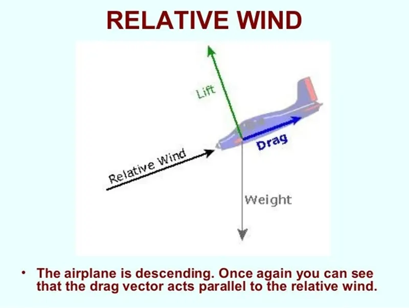
Any object moving through a fluid experiences drag - the net force in the direction of flow due to pressure and shear stress forces on the surface of the object.
The drag force can be expressed as:
Fd = cd 1/2 ρ v2 A (1)
where
Fd = drag force (N)
cd = drag coefficient
ρ = density of fluid (1.2 kg/m3 for air at NTP)
v = flow velocity (m/s)
A = characteristic frontal area of the body (m2)
The drag coefficient is a function of several parameters like shape of the body, Reynolds Number for the flow, Froude number, Mach Number and Roughness of the Surface.
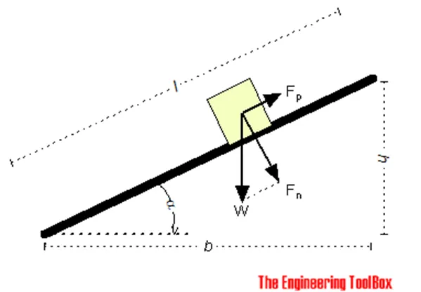
Required forces to move bodies up inclined planes.
-
If we neglect friction between the body and the plane - the force required to move the body up an inclined plane can be calculated as
Fp = W h / l
= W sin α
= m ag sin α (1)
where
Fp = pulling force (N, lbf)
W = m ag
= gravity force - or weight of body (N, lbf)
h = elevation (m, ft)
l = length (m, ft)
α = elevation angle (degrees)
m = mass of body (kg, slugs)
ag = acceleration of gravity (9.81 m/s2, 32.174 ft/s2)
By adding friction - (1) can be modified to
Fp = W (sin α + μ cos α)
= m ag (sin α + μ cos α) (2)
where
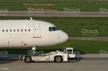
For the calculation of the power and force here we are assume parameter given below
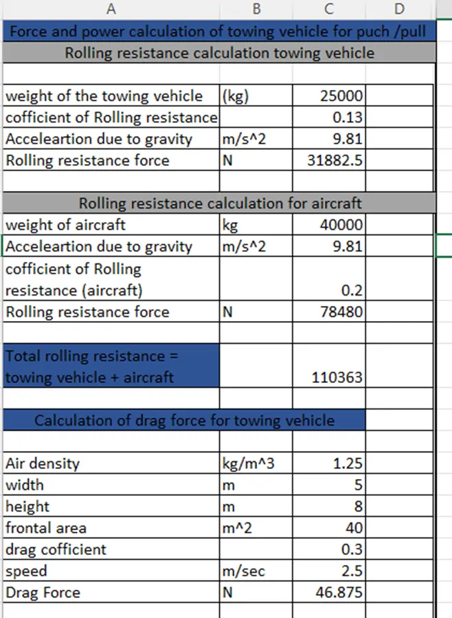
to calculate the rolling resistance of towing vehicle
assuming towing vehicle wait = 25000 kg
cofficient of rolling resistance = 0.13
Acceleration due to gravity = 9.81 m/s^2
by to puting values in formula then we got 31882.5 N
to calculate the rolling resistance of aircraft vehicle
assuming towing vehicle wait = 40000 kg
cofficient of rolling resistance = 0.2
Acceleration due to gravity = 9.81 m/s^2
by to puting values in formula then we got 110363 N
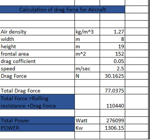
-
pulling force required to towing vehicle
pulling force = rolling force + Drag force + friction force
Friction force for the puller can be calculated
Ff= μ.W
= μ.mf.ag
Ff = friction Force
μ = Friction cofficient
W= weight
mf = friction mass
we got the total power = 1306.15 Kw after multiplying by velocity and force.
Part B:
Design an electric powertrain with type of motor, it’s power rating, and energy requirement to fulfill aircraft towing application in Simulink. Estimate the duty cycle range to control the aircraft speed from zero to highest. Make all required assumptions. Prepare a table of assumed parameters. Draw a block diagram of powertrain.
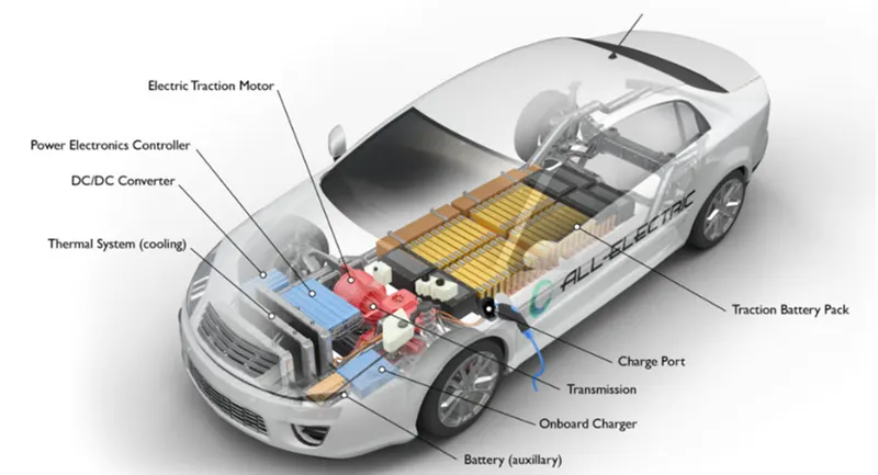
- going to design powertrain :
- 315/70 R15 IS the tyre specification for towing the truck
- i have assumed towing truck specification , not taking specific aircraft specification.
ANS: table of assumed parameters:
we already calculated force required above to towing the aircraft (40,000kg) = 110363 N
Power required for towing the aircraft = 1306.15 kw
we assuming
Tyre radius for the towing the aircraft = 0.411m
Gear Ratio = 7
Transmission Efficiency = 80%
motor efficiency = 92 %
Torque required to the wheel (Tw) = Total force * Tyre Radius
= 110363*0.411
=45359.193 Nm
Actual Power required
Pac = Power required / (Transmission Efficiency *motor efficiency )
=1306.15/ (0.8*0.92)
=1774.66 Kw =~1780 Kw
To Calculate Motor Torque
Tm = Tw/(Gear Ratio * Transmission Efficiency )
=45359.193 / 0.8*7
Tm = 8099.855 Nm
= 8.099kNm
To Calculate Actual Motor Torque
Tmac=Tm/motor efficiency
Tmac=8.099/0.92
= 8.80 kNm
To calculate battery power
The towing tractor takes 15 minutes for taxing
= Pac * hours
= 1774.66 * 0.016667
= 29.57 Kwh
so we are considering will use 210Kw Battery .
Duty Cycle = (Power required(Pac))/(rated power (battery capacity))
= 1774.66/210
=8.45
To run the towing tractor for 15 minutes with speed 7 m/s , so duty cycle varries between (0- 8.45)
At 8.45 the towing tractor reaches its maximum speed of 7m/s .
Powertrain: power train provides power to the vehicle .Power train refers to the set of components that generate the power required to move the vehicle and deliver it to the wheels.
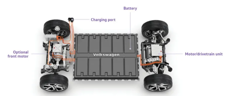
-
main components are listed below for electric vehicle :-
Electric Motor :An electric motor is an electrical machine that converts electrical energy into mechanical energy. Most electric motors operate through the interaction between the motor's magnetic field and electric current in a wire winding to generate force in the form of torque applied on the motor's shaft. An electric generator is mechanically identical to an electric motor, but operates with a reversed flow of power, converting mechanical energy into electrical energy.
Battery pack: DC-AC converter: The electrical circuits that transform Direct current (DC) input into Alternating current (AC) output are known as DC-to-AC Converters or Inverters. They are used in power electronic applications where the power input pure 12V, 24V, 48V DC voltage that requires power conversion for an AC output with a certain frequency.
DC-DC converter : DC to AC converters is mainly designed for changing a DC power supply to an AC power supply. Here, DC power supply is comparatively stable as well as positive voltage source whereas AC oscillates approximately a 0V base stage, typically in a sinusoidal or square or mode.
Thermal managment system : thermal management for EVs is to provide the right balance between driving range and passenger comfort, particularly under extreme weather conditions (hot or cold). EVs are usually equipped with electrical heaters and compressors that may puncture up to 40% driving range in winter (-7°C) and up to 20% in summer (< 35°C).
To mitigate those effects, the Thermal Systems Business Group offers smart, green and energy efficient comfort solutions that can extend EV driving range up to 40% at -15°C with optimal thermal comfort for passengers.transmission system : Transmission system is the system by means of which power developed by the engine is transmitted to road wheels to propel the vehicle. In automobiles, the power is developed by the engine which is used to turn wheels.
Motor Controller:It is a machine that is used to regulate the torque generated by the motors of electric vehicles. It does so by means of modifying the energy flow from the power sources to the motor. Motor controllers can include an automatic or manual means for starting or stopping the motor.
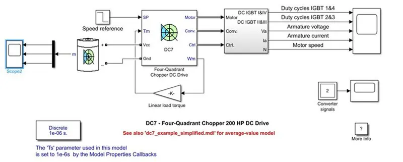
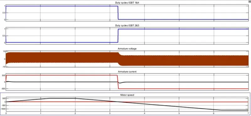
-
above plot we can understand the battery SOC, voltage , Current.
At the starting time we can see the sudden rush of starting current.
The battery voltage is set to be 80 Volt.
Here the battery percentage is reduced to 88% in the short duration of the time due to its heavy usage .
-
References
(1) Richard Bowyer (1992). Aerodynamics for the Professional Pilot. Airlife Publishing Ltd., Shrewsbury, UK.
(2) EV Powertrain Components - Basics (evreporter.com)
(3) 18 Different Types of Aircrafts, Classifications, and More: A Guide! (stylesatlife.com)