Project-1: Powertrain for aircraft in runways
Aim:
Part A:
1. Search and list out the total weight of various types of aircraft.
2. Is there any difference between ground speed and airspeed?
3. Why is it not recommended to use aircraft engine power to move it on the ground at the Airport?
4. How an aircraft is pushed to the runway when it's ready to take off?
5. Learn about take-off power, tire design, rolling resistance, tire pressure, and brake forces when landing.
Part B:
6. A. With necessary assumptions, calculate the force and power required to push/pull an aircraft by a towing vehicle.
B. Develop the model for the calculated force and power using Simulink.
7. A. Design an electric powertrain with a type of motor, its power rating, and energy requirement to fulfill aircraft towing application in Simulink. Estimate the duty cycle range to control the aircraft speed from zero to highest. Make all required assumptions. Prepare a table of assumed parameters. Draw a block diagram of the powertrain.
(Hint :DC7 Block)
B. Also, Design the parameters in an excel sheet.
Search and list out the total weight of various types of aircraft.
In an aircraft, the center of gravity (CG) is the point about which the aircraft would balance when it is suspended by that point. As the location of the center of gravity affects the stability of the aircraft, it must fall within specified limits that are established by the aircraft manufacturer. Both lateral and longitudinal balance is important, but the primary concern is longitudinal balance; that is, the location of the CG along the longitudinal or lengthwise axis.
From “Manufacturing” to “Commissioning” and from “On the Ramp” to “Take-off” there are huge variations in the weight and balance of an aircraft. It varies significantly, so striking a correct balance with all loads on an aircraft is significantly important.
Prerequisites:
- Weight of a male person – 88 kg (avg)
- Weight of a female person – 70 kg (avg)
- Weight of children (2-12) years – 35 kg (avg)
- Weight of cabin crew – 75 kg (including 3kg of crew baggage) (avg)
- The weight of fuel in aircraft can be approximated as approx 12000 kgs for 4000 km by a narrow-body aircraft (A-320).
- Payload – Passengers, Cargo, Mail, Baggage. (mainly).
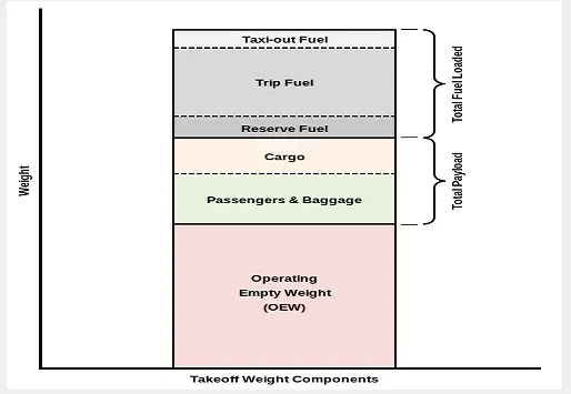
List of weights of different aircrafts:
| Aircraft | Empty Weight | Max Fuel Weight | Max Cargo Weight | Max Gross Takeoff Weight |
|---|---|---|---|---|
| Antanov AN-225 | 628,000 lbs 285,000 kg |
661,400 lbs 300,000 kg |
417,000 lbs 190,000 kg |
1,411,000 lbs 640,000 kg |
| Airbus A380-800 | 611,000 lbs 277,000 kg |
560,000 lbs 254,000 kg |
185,000 lbs 84,000 kg |
1,268,000 lbs 575,000 kg |
| Boeing 747-800 | 485,300 lbs 220,100 kg |
427,400 lbs 194,000 kg |
295,000 lbs 134,000 kg |
987,000 lbs 447,700 kg |
| Airbus A340-500 | 370,000 lbs 168,000 kg |
386,300 lbs 175,000 kg |
119,000 lbs 54,000 kg |
820,000 lbs 372,000 kg |
| Boeing 777-300ER | 370,000 lbs 168,000 kg |
320,800 lbs 145,500 kg |
148,000 lbs 67,100 kg |
776,000 lbs 352,000 kg |
| Boeing 787-10 | 299,000 lbs 135,500 kg | 223,500 lbs 101,500 kg |
126,300 lbs 57,300 kg | 560,000 lbs 254,000 kg |
| Boeing 737-900 | 98,500 lbs 44,700 kg |
53,100 lbs 24,000 kg |
44,600 lbs 20,200 kg |
187,000 lbs 85,000 kg |
| Airbus A320-100 | 93,900 lbs 42,600 kg |
48,700 lbs 22,100 kg |
44,000 lbs 20,000 kg |
150,000 lbs 68,000 kg |
| Embraer 190 | 63,500 lbs 28,800 kg |
28,600 lbs 13,000 kg |
28,800 lbs 13,100 kg |
106,000 lbs 48,000 kg |
| Gulfstream G650 | 54,000 lbs 24,500 kg | 48,200 lbs 21,900 kg | 6,500 lbs 3,000 kg |
100,000 lbs 45,200 kg |
| Bombardier CRJ900 | 48,160 lbs 21,850 kg | 19,600 lbs 8,900 kg | 6,075 lbs 2,760 kg | 80,500 lbs 36,500 kg |
| Bombardier Q400 | 39,300 lbs 17,800 kg |
11,700 lbs 5,300 kg |
18,700 lbs 8,500 kg |
62,000 lbs 28,000 kg |
| Learjet 75 | 13,900 lbs 6,300 kg | 6,060 lbs 2,750 kg |
2,900 lbs 1,300 kg |
21,500 lbs 9,700 kg |
| Cessna Citation CJ4 | 10,300 lbs 4,700 kg | 5,800 lbs 2,650 kg |
2,200 lbs 1,000 kg | 17,200 lbs 7,800 kg |
| Beechcraft King Air B100 | 7,100 lbs 3,200 kg | 3,200 lbs 1,450 kg |
4,150 lbs 1,900 kg |
12,000 lbs 5,400 kg |
| Diamond DA50 RG | 3,200 lbs 1,450 kg |
340 lbs 155 lbs |
1,250 lbs 560 kg |
4,400 lbs 2,000 kg |
| Beechcraft Bonanza G36 | 2,500 lbs 1,150 kg | 450 lbs 200 kg |
850 lbs 385 kg |
3,660 lbs 1,660 kg |
| Cessna 206H | 2,200 lbs 990 kg |
520 lbs 235 kg |
1,150 lbs 520 kg |
3,600 lbs 1,630 kg |
| Sirrus SR22 | 2,250 lbs 1,000 kg | 485 lbs 220 kg |
950 lbs 430 kg |
3,600 lbs 1,630 kg |
| Cessna 172R | 1,700 lbs 770 kg |
380 lbs 170 kg |
560 lbs 255 kg |
2,425 lbs 1,100 kg |
Is there any difference between ground speed and airspeed?
Yes, there is a difference between ground speed and airspeed.
for understanding airspeed and the ground speed first, we have to understand the concept of the relative velocity:
the vector difference between the velocities of two bodies: the velocity of a body with respect to another regarded as being at rest.
So, In the air crafts or any other airborne vehicle, the velocity of the vehicle encounters the air velocities which means they both have some velocity against any reference.
To properly define the relative velocity, it is necessary to pick a fixed reference point and measure velocities relative to the fixed point. In this slide, the reference point is fixed to the ground, but it could just as easily be fixed to the aircraft itself. It is important to understand the relationships between wind speed ground speed and airspeed.
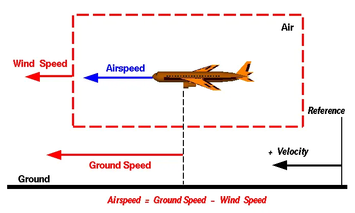
Wind Speed
For a reference point picked on the ground, the air moves relative to the reference point at the wind speed. Notice that the wind speed is a vector quantity and has both a magnitude and a direction. Direction is important. A 20 mph wind from the west is different from a 20 mph wind from the east. The wind has components in all three primary directions (north-south, east-west, and up-down). In this figure, we are considering only velocities along the aircraft's flight path. A positive velocity is defined to be in the direction of the aircraft's motion. We are neglecting crosswinds, which occur perpendicular to the flight path but parallel to the ground, and updrafts and downdrafts, which occur perpendicular to the ground.
Ground Speed
For a reference point picked on the ground, the aircraft moves relative to the reference point at the ground speed. Ground speed is also a vector quantity so a comparison of the ground speed to the wind speed must be done according to rules for vector comparisons.
Airspeed
The important quantity in the generation of lift is the relative velocity between the object and the air, which is called the airspeed. Airspeed cannot be directly measured from a ground position but must be computed from the ground speed and the wind speed. Airspeed is the vector difference between the ground speed and the wind speed.
Airspeed = Ground Speed - Wind Speed
On a perfectly still day, the airspeed is equal to the ground speed. But if the wind is blowing in the same direction that the aircraft is moving, the airspeed will be less than the ground speed.
Why is it not recommended to use aircraft engine power to move it on the ground at the Airport?
Pilots and airlines rely on aircraft tugs to perform towing and pushback operations for commercial, private, and military aircraft with general ease. The traction design incorporated into aircraft towing equipment means safe movement and stops, even on snow and ice. But there are even more reasons why airlines rely on airport tugs.
Aircraft towing equipment is typically used for the towing and pushback process to avoid some of the significant hazards posed by aircraft engines. When an aircraft's engine is activated, the thrust can create a high-speed wind that can easily cause damage to the airport terminal, surrounding ground vehicles, jetway, baggage, and most importantly, ground personnel.
Suppressing the use of engines is especially important when towing a large aircraft, as their more powerful thrust capabilities can become exceedingly dangerous. Engine thrust can easily send any loose items airborne, turn the tiniest grains of dust into hazardous projectiles and create debris that can cause damage to multi-million dollar engines. Additionally, aircraft engines consume a great deal of fuel and generate extreme noise that can be harmful to ground personnel. Using a pushback tug for aircraft is simply a more economical and safer option than running the engines.
How an aircraft is pushed to the runway when it's ready to take off?
Airplanes have engines, and they can use them to move forward along the ground. So they push themselves to the runway.
It is true that most of the time, a small vehicle is needed to push the larger commercial airplanes backward away from the terminal building because even if a plane can reverse its thrust, it’s not always safe to hit the buildings with that reverse thrust. So the little trucks push the bigger planes back away from the buildings, but after that, the planes can apply a small amount of engine power to roll forward just as all airplanes can.
Learn about take-off power, tire design, rolling resistance, tire pressure, and brake forces when landing.
Take-off power
The amount of power that an engine is allowed to produce for a limited period of time for takeoff. The use of takeoff power is usually limited to 5 min for reciprocating engines and up to 2½ min for gas turbine engines. This may not always be the case. Specifically, with respect to reciprocating engines, it is the brake horsepower developed under standard, sea-level conditions and under the maximum conditions of the crankshaft rotational speed and the engine manifold pressure
approved for the normal take-off.
It is limited in continuous use to the period of time shown in the approved engine specifications. With respect to gas turbine
engines, it is the thrust developed under static conditions at a specified altitude and atmospheric conditions of the rotor shaft rotational speed and gas temperature approved for the normal takeoff. It is limited in continuous use to the period of time
shown in the approved engine specifications.
Tire design:
The tire design of the aircraft is critical as they required high speed like a race car as well as the high load-bearing capability at the same time. They go through cyclic exposure to varying temperatures and pressures. These factors make aircraft tire design a critical process and tire maintenance an ever-important step in safe aircraft operation.
Engineers are challenged with designing tires with cool running, heat-resistant materials while simultaneously exceeding tire service requirements. Tire prototypes are put through rigorous tests that simulate cycles of landings, take-offs, and taxi operations. It is only after the tires pass all mandatory tests and meet the requirements of the aircraft manufacturer and airworthiness authorities that the tires are put into production.
Two types of tires are used in aircraft applications — bias-ply tires and radial tires.
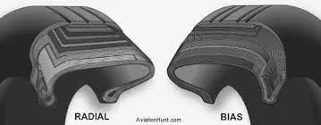
Bias-ply tire construction
A cutaway of a typical bias-ply tire is shown in Figure 1. Bias-ply tires are popular choices for aircraft tires because of their durability and retreadability.
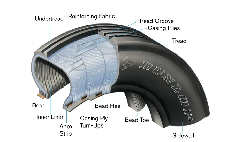
Tread: The tread is made of rubber mixed with other additives to obtain the desired level of toughness, durability, and resistance to wear. The tread pattern is designed to aircraft operational requirements, with the ribbed tread design used widely due to its good traction under varying runway conditions.
Sidewall: The sidewall is a protective layer of rubber that covers the outer casing ply. It extends from the tread edge to the bead area.
Tread Reinforcing Ply: One or more layers of fabric that strengthen and stabilize the tread area for high-speed operation. It also serves as a reference for the buffing process when tires are retreaded.
Radial-ply tire construction:
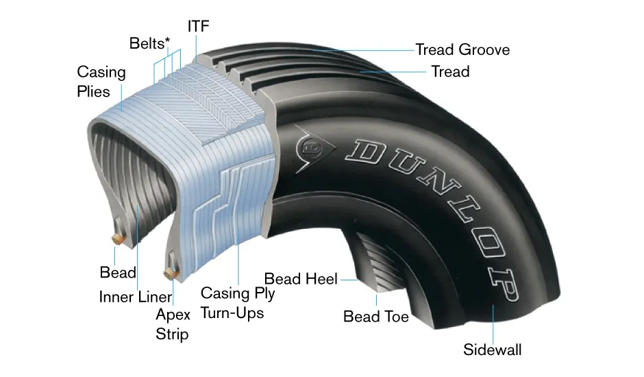
A typical radial tire is illustrated in Figure 2. With their rigid belt, they provide increased landings and reduced rolling resistance. They have fewer components in their construction and are lighter than similarly sized bias-ply tires.
Overlay: A layer of reinforcing rubber-coated fabric is placed on top of the belts to aid in high-speed operation.
Belt Plies: A composite structure that stiffens the tread area for increased landings. The belt plies increase the tire strength in the tread area.
Casing Plies: As in bias-ply tires, the casing plies are layers of rubber-coated fabric. However, unlike those in bias plies that run at opposite angles to one another, radial plies run radially from bead to bead.
Rolling resistance:
Tire rolling resistance is the energy that your vehicle needs to send to your tires to maintain movement at a consistent speed over a surface. In other words, it is the effort required to keep a tire rolling. The main contributor to rolling resistance is the process known as hysteresis.
Tyre pressure:
Tests of airliner aircraft tires have shown that they are able to sustain pressures of a maximum of 800 psi (55 bar; 5,500 kPa) before bursting. During the tests the tires have to be filled with water, to prevent the test room from being blown apart by the energy that would be released by gas when the tire bursts.
Aircraft tires are usually inflated with nitrogen to minimize expansion and contraction from extreme changes in ambient temperature and pressure experienced during flight. Dry nitrogen expands at the same rate as other dry atmospheric gases (normal air is about 80% nitrogen), but common compressed air sources may contain moisture, which increases the expansion rate with temperature.
Aircraft tires generally operate at high pressures, up to 200 psi (14 bar; 1,400 kPa) for airliners, and even higher for business jets. The main landing gear on the Concorde was typically inflated to 232 psi (16.0 bar), whilst its tail bumper gear tires were as high as 294 psi (20.3 bar)
Brake force when landing:
The most common type of brake used on aircraft is the disc brake. Disc brakes function by exploiting friction between rotating and stationary discs inside the brake.
Upon receiving a command signal to brake — from the pilot depressing a foot pedal or from the auto brake system — actuators in the brake move a piston to squeeze the discs together, generating a frictional force that slows the rotation of the wheel. The friction between the discs generates heat as the aircraft’s kinetic energy is converted to heat energy. In this function, the brakes act as a heat sink, absorbing tremendous amounts of heat as the aircraft sheds kinetic energy. During RTO stops, the temperature of carbon disc brakes can exceed 1,800° C.
The primary design considerations for aircraft brakes include the number of discs, the diameter of the discs, and the material of the discs.
A major design point around which aircraft brakes are designed is the worst-case scenario of rejected takeoff (RTO) at the maximum rolling speed V1, known as the decision speed. Above V1, a takeoff could not be safely aborted without the serious risk of the airplane failing to stop before the end of the runway. In this situation, the brakes need to absorb more energy than in any other scenario.
A. With necessary assumptions, calculate the force and power required to push/pull an aircraft by a towing vehicle.
The force to move an airplane on an absolute flat runway with no wind at constant low speed is equal to the rolling resistance between the plane and the tarmac.
The rolling resistance for the airplane can be calculated as
Fr = c mr ag
where
Fr = rolling resistance (N)
c = rolling resistance coefficient
mr = rolling mass (kg)
ag = acceleration of gravity (9.81 m/s2)
Force required to pull an airplane at constant low speed on tarmac
assuming the mass of a plane is 70000 kg and
The mass of towing vehicle is 40000 kg
therefore the total weight that the engine has to pull or push is 70000+40000 =110000
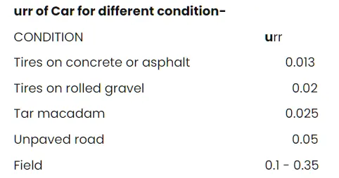
the rolling coefficient between the aircraft wheel and the tarmac is 0.02
- the force required to overcome the rolling resistance can be calculated as:
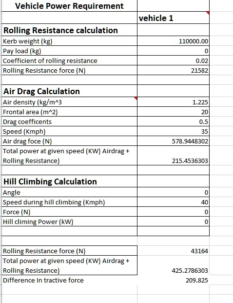
Fr = 0.02*110000*9.81
= 21582 N
now, the aerodynamic drag force:
The drag coefficient for a streamlined body Cd= 0.05,
air density ρ = 1.25 kg/m^3
Assuming the frontal area of a plane by considering the nose of the plane and the wings
A = 20 m^2
Fad = 0.5*`rho`*A*Cd*v^2
where, v = velocity m/s
assuming that the towing velocity of the truck is 35 km/hr = 9.72m/s
Fad = 0.5*1.25*20*0.05*(9.72)^2
= 59.50 N
Fhc = m*g*sin (Ψ)
where,
m = mass
g = accelartaion due to gravity
Ψ = grading angle
since the plane is moving in the flat track the hill-climbing force will be 0 because the grading angle is 0
therefore,
the total Tractive force require to pull the plane
Ft = Fr+Fad +Fhc
= 21582+59.50
= 21642 N
Therefore
power required = Fte*v
= 21642* 9.72 =210,355.3 J
Develop the model for the calculated force and power using Simulink.
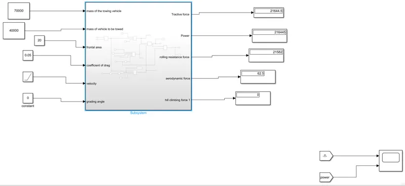
The subsystem is created to Input the different constraints of the vehicle.
and the output port of the subsystem generates the output.
The input parameters which are taken by the subsystem are as follows:
- Mass of the vehicle
- frontal area
- Coefficient of drag
- Velocity
the output generated by the subsystem is as follows :
- Tractive force
- Rolling resistance force
- Aerodynamic force
- Hill climbing force
- Power
The scope is connected to tracing the Tractive force and power increment with the increase in velocity from 0 to 10 m/s with the help of the RAMP block.
the display block is connected with the output port to display the various forces of the vehicle and the power.
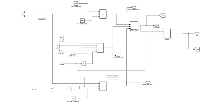
Inside the Subsystem, the calculation of the forces and the power is done with help of the following Simulink blocks:
- Constant block: constant block is used to provide the different constant factors like air density, gravity, etc.
- Product block: The product block is used to calculate the products.
- Sum block: The sum block did the summation of forces.
- sin: Sin block is used to calculate the sin value of the grading angle.
- D2R: D2R block basically convert degree into radians as the sin block takes the input values in radians.
- Goto/From: Goto block is used to send the signal of tractive force and power to the From block which is connected to the scope.
The calculations of the forces are done above.
Results:
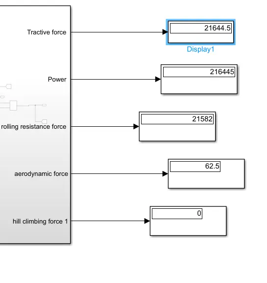
Scope results:
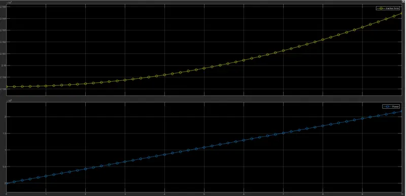
The first graph shows an increase in the tractive force for the velocity range between 0 to 10 m/s.
The second graph shows the increment in the power for the velocity range of 0 to 10 m/s.
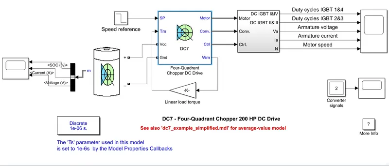
A. Design an electric powertrain with a type of motor, its power rating, and energy requirement to fulfill aircraft towing application in Simulink. Estimate the duty cycle range to control the aircraft speed from zero to highest. Make all required assumptions. Prepare a table of assumed parameters. Draw a block diagram of the powertrain.
(Hint: DC7 Block)
Based on the calculation in above question 6 A
the force required to push or pull the aircraft = 21642 N
Power required = 210355.3 J
Assuming that
the radius of the tire = 25 in = 0.635m
gear ration = 8
transmission efficiency (ηt) = 90%
motor efficiency (ηm) = 96%
now,
the torque required on the wheel = total force*wheel radius
= 21642*0.635 = 13742.67 N-m
motor torque = wheel torque/(gear ratio*ηt)
13742/(8*0.9) =15269.6N-m
for ηm = 96% the reqiured torque (Tm) = 15269.6/0.96 = 15906 N-m
similarly, the total power required by the motor considering all the efficiencies
(pt) = 210355.3 /(0.9*0.96) = 243466.7 J
let us assume the towing operation is done for 20 min
which is eqaul to the = 0.33 hours
the total energy consumed = 243466.7*0.33 = 81155.5 kWh
considering the battery capcity is 325 kW is used by the towing vehicle
then, The duty cycle (d) = (required power/ (rated power) = 243.46/325 = 0.75
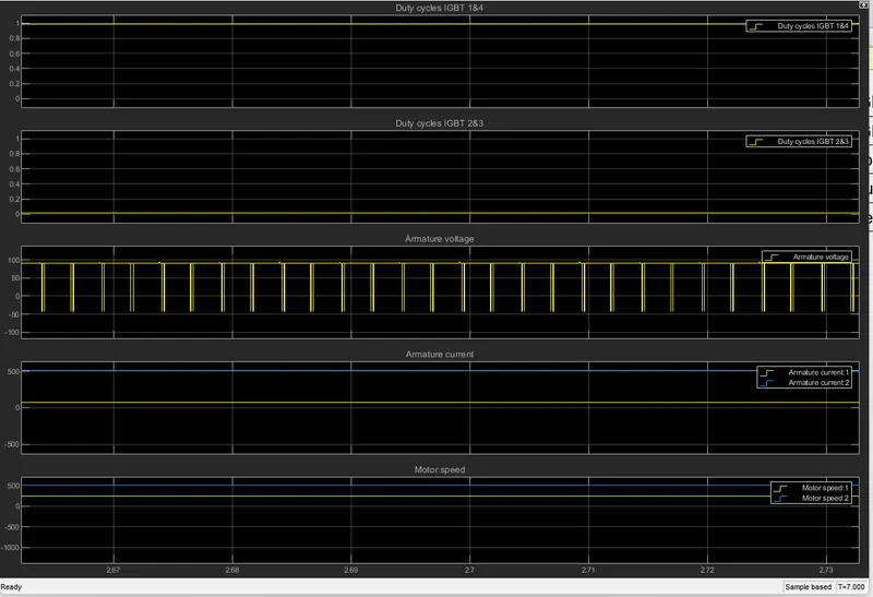
therefore the controller will be able to provide a duty cycle ranging from 0 to 75% in order to control the towing speed.
Model:
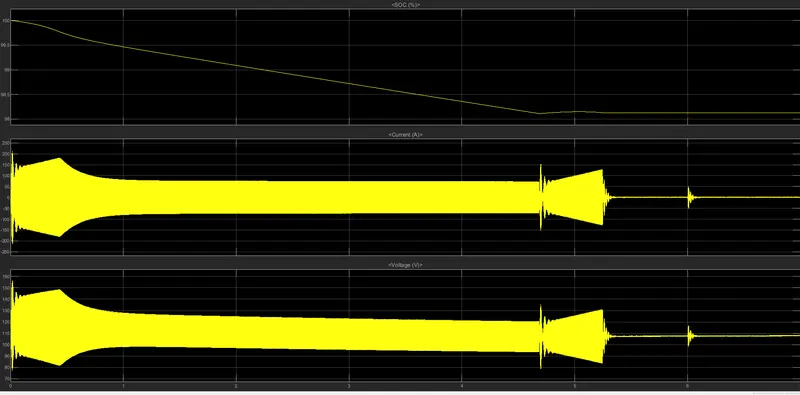
Result:
Battery :
SOC
voltage
current
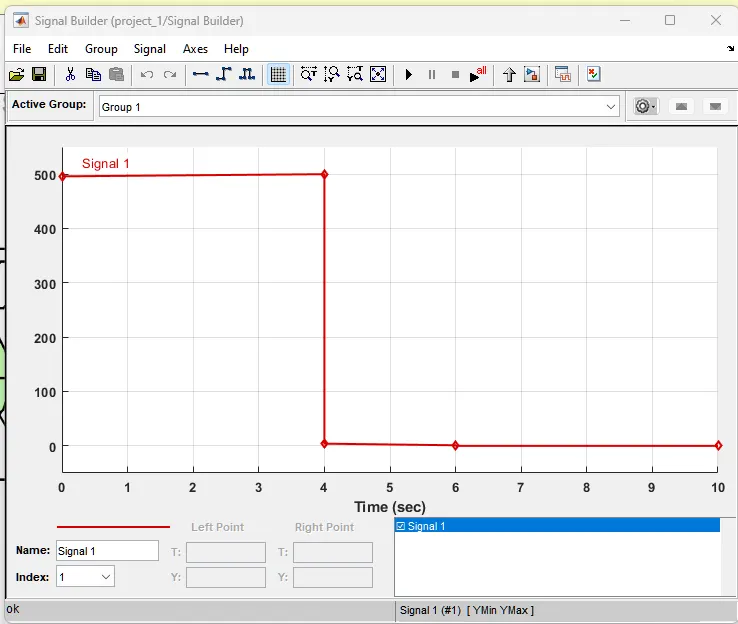
Signal builder
B. Also, Design the parameters in an excel sheet.
References:
http://aviationavi.com/all-kinds-of-weight-for-an-aircraft/
https://pilotteacher.com/how-much-do-airplanes-weigh-with-20-examples/
https://www.grc.nasa.gov/www/k-12/airplane/move.html