Project-1: Powertrain for aircraft in runways
Objective :
Part A:
1. Search and list out the total weight of various types of aircrafts.
2. Is there any difference between ground speed and air speed?
3. Why is it not recommended to use aircraft engine power to move it on the ground at Airport?
4. How an aircraft is pushed to runway when its ready to take off?
5. Learn about take off power, tyre design, rolling resistance, tyre pressure, brake forces when landing.
Part B:
6. A. With necessary assumptions, calculate the force and power required to push / pull an aircraft by a towing vehicle.
B. Develop the model for the calculated force and power using Simulink.
7. A. Design an electric powertrain with type of motor, it’s power rating, and energy requirement to fulfill aircraft towing application in Simulink. Estimate the duty cycle range to control the aircraft speed from zero to highest. Make all required assumptions. Prepare a table of assumed parameters. Draw a block diagram of powertrain.
(Hint :DC7 Block)
B. Also, Design the parameters in excel sheet.
A:
1. Search and list out the total weight of various types of aircrafts.
The different terms represent different weights or masses. For each flight, the weights are taken into account for several reasons.
A brief description about these is below:
| Airbus A380-800 | 575,000 | 394 |
| Boeing 747-8F | 447,700 | 346.091 |
| Boeing 747-8 | 443,613 | 306.175 |
| Boeing 747-400ER | 412,770 | 295.742 |
MANUFACTURER EMPTY WEIGHT (MEW)
Also called Manufacturer's Weight Empty (MWE) or Licensed Empty Weight
It is the weight of the aircraft "as built" and includes the weight of the structure, power plant, furnishings, installations, systems and other equipment that are considered an integral part of an aircraft.
This excludes any baggage, passengers, or usable fuel2.
ZERO FUEL WEIGHT (ZFW)
This is the total weight of the airplane and all its contents (including unusable fuel), but excluding the total weight of the usable fuel on board.
As a flight progresses and fuel is consumed, the total weight of the airplane reduces, but the ZFW remains constant.
Maximum zero fuel weight (MZFW) is the maximum weight allowed before usable fuel and other specified usable agents (engine injection fluid, and other consumable propulsion agents) are loaded.
OPERATING EMPTY WEIGHT (OEW) (Roughly equivalent to basic empty weight on light aircraft)
It is the basic weight of an aircraft including the crew, all fluids necessary for operation such as engine oil, engine coolant, water, unusable fuel and all operator items and equipment required for flight but excluding usable fuel and the payload.
payload
It is the carrying capacity of an aircraft. It includes cargo, people, extra fuel. In the case of a commercial airliner, it may refer only to revenue-generating cargo or paying passengers.
MAXIMUM TAKE-OFF WEIGHT (MTOW)
This is the maximum weight at which the pilot of the aircraft is allowed to attempt to take off3.
REGULATED TAKE OF WEIGHT (RTOW)
Depending on different factors (e.g. flap setting, altitude, air temperature, length of runway), RTOW or maximum permissible takeoff weight varies for each takeoff. It can never be higher than MTOW.
MAXIMUM LANDING WEIGHT (MLW)
This maximum weight at which an aircraft is permitted to land.
The following image depicts takeoff weight components.
MAXIMUM RAMP WEIGHT (MRW)
also called maximum taxi weight (MTW)
It is the maximum weight authorized for maneuvering (taxiing or towing) an aircraft on the ground.
AIRCRAFT GROSS WEIGHT (AGW)
It is the total aircraft weight at any moment during the flight or ground operation. This decreases during flight due to fuel and oil consumption.
2. Is there any difference between ground speed and air speed?
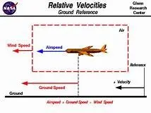
AIR SPEED: It is simply the speed at which an aircraft is moving relative to the air it is flying in. Also, it is the sp which the air is flowing around the aircraft's wings. There are two types of Air speed:
i. Indicated Air Speed (IAS): It is the measured speed of an airplane as it moves through the air. The indicated airspeed is what registers on the cockpit air speed indicator, and it is based on pressure readings collected by the pitot-static system. The indicated airspeed is inversely correlated with the true airspeed based on altitude.
If true airspeed remains constant, and the only variable to change is the aircraft's altitude, at a higher altitude, the air is thinner and there are fewer molecules to enter the pitot tube and create pressure. The gauge will register a lower indicated airspeed.At a lower altitude, the air is denser, and the increase in molecules causes a higher pitot pressure which will translate to a higher indicated airspeed.
The indicated airspeed as displayed on your airspeed indicator gauge in knots of indicated airspeed (KIAS) is used for aircraft speed limits, speed changes, and ATC speed restrictions. The published v-speeds for each aircraft are also relayed in indicated airspeed. True Air Speed (TAS): It is the speed the airplane moves at in relation to the air mass it is flying through. If the air is perfectly still and the aircraft is flying straight and level, the true airspeed will be the same as groundspeed. True airspeed is calculated by taking the indicated airspeed and adjusting for pressure and temperature variables.If the airplane is flying into a headwind, the true airspeed will be higher than groundspeed. This is because the plane and the air mass are moving in opposite directions, so they pass each other more rapidly and the pitot tube reads a higher pressure and therefor a higher true airspeedThe inverse is true with a tailwind. In this case, the true airspeed will be less than groundspeed because the air mass is moving with the airplane, so the relative speed between the plane and the air is less than it is between the air and a stationary point on the ground.True airspeed is also impacted by altitude. At higher altitudes, with less dense air, the aerodynamic drag on the plane decreases and the true airspeed increases. The rate of increase is 2% per thousand feet.Pilots use true airspeed in kriots (KTAS) for performance measurements and flight planning.
GROUND SPEED: It is the speed at which the airplane is actually moving over the ground. Groundspeed takes your true airspeed and adjusts for wind. A tailwind pushes the plane faster relative to the ground than to the airmass, so the groundspeed would be higher than the true airspeed. A headwind slows the plane's forward progress relative to the ground while increasing its speed relative to the airmass, so the groundspeed would be lower than the true airspeed Groundspeed is used by pilots when making time and distance calculations.Ground speed is the actual speed that an aircraft travels over the ground, and is also referred to as "shadow speed." Ground speed combines the aircraft's air speed and the wind speed relative to the aircraft's direction of flight. An aircraft's air speed is determined not by how much distance it covers in a set time, but by a combination of its forward speed and the speed of the wind that is blowing towards the aircraftsA wing must have air moving over it to create lift. Too little moving air and the airplane will 'stall, or lose elevation very rapidly. The stall speed is when the wings no longer create lift, and the airplane falls from the sky. As an example. let's say that an aircraft has a stall speed of 20 knots. That does not mean that the aircraft needs to propel itself at 20 knots, but rather that the air moving over the wing must be traveling at 20 knots or more so that the aircraft can stay aloft. Therefore, a gust of wind that is traveling at 20 knots towards the aircraft will allow the airplane to hover stationary over areaGround speed and Speed are not always the same speed. On a windy day, an airplane may have an Air Speed of 80 knots but a Ground Speed of only 60 knots. The term "shadow speed comes from the speed of the airplane's shadow on the ground. If an aircraft has an Air Speed of 80 knots but a ground speed of 60 knots, a car that follows the shadow will only need to go 60 knots to keep the same speed as the airplane.Most people have heard of head and tailwinds. Tailwinds will help push an aircraft faster, so that it reaches its destination more quickly, while a headwind pushes against the aircraft and slows it down. A headwind will detract from an aircraft's Ground Speed, while a tailwind will increase it.
Difference between Ground Speed and Air Speed
True airspeed is simpy the speed at which an aircraft is moving relative to the air it is flying in. As such, it's also the speed at which the air is flowing around the aircraft's wings.Ground speed, on the other hand, is the aircraft's speed relative to the ground. One thing that should be noted here is that it's its horizontal rather than vertical speed - an aircraft climbing completely vertically would have a ground speed of zero.In other words, while airspeed is what determines whether there is enough airflow around an aircraft to make it fly. ground speed is what determines how fast an aircraft will get to its destination.
3. Why is it not recommended to use aircraft engine power to move it on the ground at Airport?
A.) Usually, Aircrafts run on the ground using Engine power but it is not used at rated comparing t So it uses less speed. The following are some limitations why we can't use the full Engine power on ground
i. The area infront of the jet engine creates a space where any equipment or people can be sucked into the engine anything is too close.
ii. Applying the gas can create a blast behind the engines.
iii. Areas infront of the engines are critical factors when applying the power to them, so we can't ignore them easily.
iv. People, Things can be damaged if they are tear to the plane from the jet blast.
v. Air intake is very powerful that it can even suck the human bodies.
vi. Due to high suction it may intake the small dust particles, stones, papers etc which may damage the engines.
vii. The noise obtained from the plane is more and also fumes gave more heat.
So it is not recommendable to move the aircraft on ground with Engine power which has dangerous affects.
4. How an aircraft is pushed to runway when its ready to take off?
A] Take Off:
Take-off is the phase of flight in which an aerospace vehicle leaves the ground and becomes airborne. For light aircraft, usually fullpower is used during take-off. Large transport category (airliner) aircraft may use a reduced power for take-off, where less than fullpower is applied in order to prolong engine life, reduce maintenance costs and reduce noise emissions. In some emergency cases,the power used can then be increased to increase the aircraft's performance. The aircraft is permitted to accelerate to rotation speed often referred to as V . The term rotation is used because the aircraft pivots around the axis of its mainlanding gear while still on theground, usually because of gentle manipulation of the flight controls to make or facilitate this change in aircraft altitude.Fixed-wing aircraft designed for high-speed operation such as commercial jet aircraft have difficulty generating enough lift at thelow speeds encountered during takeoff. These are therefore fitted with high lift devices, often including slats and usually flaps, whichincrease the camber and often area of the wing, making it more effective at low speed, thus creating more lift. These are deployedfrom the wing before takeoff, and retracted during the climb. They can also be deployed at other times, such as before landing.The speeds needed for take-off are relative to the motion of the air (indicated airspeed). A headwind will reduce the ground speedneeded for take-off, as there is a greater flow of air over thewings. Typical take-off air speeds for jetliners are in the range of 240–285km/h ,130–154 kn; 149–177 mph For a given aircraft, the take-off speed is usually dependent on the aircraft weight; the heavier the
weight, the greater the speed needed.Take off performance can be predicted using a simple measure of the acceleration of theaircraft along the runway based on force equilibrium. The forces involved will be
dv/dt= T-D-F/m
T – Thrust of propulsion system pushing aircraft along runway.
D – Aerodynamic Drag of vehicle resisting the aircraft motion.
F – Rolling resistance friction due to the contact of wheels or skids on the ground.
During take-off run the imbalance in these forces will produce an acceleration along the runway.
where dV/dt is the acceleration along the runway and m is the mass of the vehicle.
B] Tyre Design:
Tyres are one of the most important components of aircraft. They help to absorb the shock of landing and provide cushioning. It alsoprovides the necessary traction for braking and stopping of an aircraft.
An aircraft tyre is designed to withstand extremely heavy loads while landing, take off, taxing and parking. The number of wheelsrequired for aircraft increases with the weight of the aircraft, as the weight of the aeroplane needs to be distributed more evenly.A Boeing 737NG & 737MAX uses 6 wheels, Boeing 787 uses 10 wheels, Boeing 777 uses 14 wheels and Airbus A380 uses 22 wheels.Aircraft tyres work under extreme conditions, carrying up to 340 tons and accelerating at over 250 km/hour at takeoff, in addition toenduring varied environmental stress when in flight and taxiing.
Design and Construction of aircraft tyre Carcass plies are used to form the tire. They are sometimes called casing plies. An aircraft tyre is constructed for the purpose it
serves.
1. They support the weight of an aircraft while it is on the ground.
2. It also provides the necessary traction for braking and stopping of an aeroplane.
3. Tyre also helps to absorb the shock of landing and provide cushioning the roughness of takeoff, roll-out, and taxi operations.
Let’s go through some technical aspects of the tyre.
Retreading – Retreading is methods of restoring a worn tyre by renewing the tread area or by renewing the tread area plus one or
both sidewalls. Repairs are included in the tyre retreading process.
Load Rating – Load rating is the maximum permissible load at a specified inflation pressure
Ply Rating – Ply Rating is used to identify the maximum recommended load rating and inflation pressure for a specified tyre. It is anindex of tyre strength.
Speed Rating – The speed rating is the maximum takeoff speed to which the tyre has been tested.
Skid Depth – Skid depth is the distance between the tread surface and the deepest groove as measured in the mould.
Aircraft tyres must have an approved speed and load rating and have sufficient clearance when retracted through landing gear to allow for tyre growth. Tyre growth is the increase in the size of the tyre due to centrifugal forces at high speed.
Aircraft tyres may be Tube-type or Tubeless
Tubeless tyres are more advantageous over tube-type. There is no longer the use of tube-type tyre in recent aviation. Nowadays all airliners are using tubeless tyres. Tubeless that are meant to be used without a tube has the word TUBELESS on the sidewall of the tyre.
Aircraft tyres may be Radial or Bias
Almost all airliners are using Radial tyre. Bias is an older design, and it’s mainly used for road vehicles. Radial tyres have the word. RADIAL on the sidewall. Radial tires are more expensive than bias-ply tyres. Radial tires are in demand because of their lower life cycle cost and long term value.
The basic difference between a radial tyre and bias (cross-ply) tyre is the lay of the plies within the tyre carcass. The remainder of the tyre is very similar in construction in both.
Tyres are critical components of aircraft. The choice of tyre totally depends on the aircraft manufacturer. Radial tyres having a feature of rigid belt and flexible carcass which providing more number of landings and less rolling resistance.
Another means of classifying an aircraft tyre is by the direction of the plies used in the construction of the tyre, either bias or radial. Traditional aircraft tyres are bias-ply tyres.
Construction of Aircraft Radial & Bias Tyre
A bias-ply tyre has the fabric bias oriented with and across the direction of rotation and the sidewall. Since fabric can stretch on thebias, the tyre is flexible and can absorb loads. Tyre strength is obtained by adding plies.
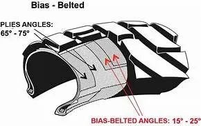
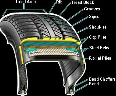
1. Apex strip: A triangular piece of stiff rubber which is fitted onto the bead core to taper the rigid bead into the flexible body plies in the sidewall.
2. Bead heel: Outer edge of the bead.
3. Bead toe: Inner edge of the bead.
4. Breaker: Breakers are fabric plies placed directly on the upper-most ply beneath the tread rubber. They disperse stress throughout.the tire. This breaker is utilized in a limited number of Bridgestone aircraft tires.
5. Chafer strip: Reinforces the beads and protects the cord body-plies from damage from rim friction or from damage when
replacing the rim.
6. Carcass plies: Each nylon ply is held by wire beads across the tire to keep the tensile strength at the proper level, and is folded to the side of the sidewall. Each ply is provided with cushion rubber to reduce shearing force produced between the cords of the tire when it is deformed. Multiple coated-nylon cords are crossed alternately on the bias to make the carcass.
7. Decoration line: A projecting, embossed line molded between the shoulder and sidewall of a tire. Its purpose is for decoration only.
8. Flipper strip: A strip of material which is wrapped around the bead bundle and filler to add support and help taper the assembly into the sidewall.
9. Innerliner: A sheet of special rubber laminated to the inside of the first casing ply of the tubeless tire so as to ensure retention of pressure when the tire is inflated.
10. Ply turn-ups: The turned-up ends of plies around the bead. Other plies lock the ends into place.
11. Tread reinforcing fabric: Nylon cord plies located in the tread between the tread groove and the outer ply of the carcass which reduce tread squirm and increase stability for high speed operations.
12. Rim line: This line is provided near the beads to allow inspection of how the tire fits with the rim.
13. Shoulder: The area on the side of the tire between the sidewall and the tread.
14. Sidewall: The side area of the tire located between the buttress and the beads. Composed of rubber, it protects the carcass from damage.
15. Tread: A layer of rubber on the outer circumference of a tire, its major functions are to protect the casing from cuts, withstand high speed during take-off and landing, provide traction, resist wear, provide durability under a wide range of temperatures and to ensurestability (in particular, the effective discharge of water on wet runways). The tread compound is designed to suit a wide range of operations.
16. Undertread: A rubber layer provided for use in retreading the tire and which provides adhesion of tread to the cord body.
Bridgestone makes this rubber layer thick enough to ensure a high number of retreads.ape of the tire and keep it securely fixed to the rim. The wire beads are wrapped with fabric.
18. Venting hole: The hole through which gas is vented from inside the carcass plies.
A radial tyre has the fibre strands of the ply fabric oriented with and at 90° to the direction of rotation and the tyre sidewall. This restricts flexibility bidirectionally and the flexibility of the sidewall while it strengthens the tyre to carry heavy loads.
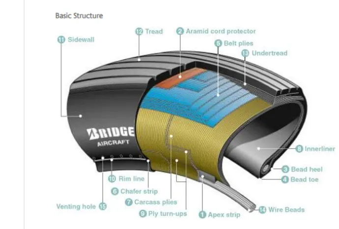
1. Apex strip: A triangular piece of stiff rubber which is fitted onto the bead core to taper the rigid bead into the flexible body plies in the sidewall.
2. Aramid cord protector: The tire is constructed with an aramid ply insert between the tread and the top belt to prevent damage to the tire belts.
3. Bead heel: Outer edge of the bead.
4. Bead toe: Inner edge of the bead.
5. Belt plies: Angled belt plies which serve to add strength to the tire especially in the tread area.
6. Chafer strip: Protective layer of rubber and fabric which prevents chafing between cord body plies and the wheel.
7. Carcass plies: Layers of rubber-coated fabric plies which have the cords running radially from bead to bead. These provide the tire with strength in the sidewall area. tubeless tire to insure retention of air when tire is inflated.
9. Ply turn-ups: The turned-up ends of plies around the bead. Other plies lock the ends into place.
10. Rim line: A line provided near the beads to allow inspection of how the tire fits with the rim.
11. Sidewall: The side area of the tire located between the shoulder and the beads. Composed of rubber, it protects the carcass from damage.
12. Tread: The functions of the radial tread are the same as those defined for the bias tire.
13. Undertread: A rubber layer provided for use in retreading the tire and which provides adhesion of tread to the tire carcass.Bridgestone makes this rubber layer thick enough to ensure a high number of retreads.
14. Wire beads: Two wire bundles (one for each bead) which help to maintain the shape of the tire and anchor it securely to the rim.
15. Venting hole: The hole through which gas is vented from inside the carcass plies. Punture and Cut Resistance of Tyre
Most radial tyres are resistant to penetrations and cuts, especially in the tread area due to their unique construction process.In fact, only a small portion of the radial tyre will be affected in case of any damage.
Bias-ply tires are cut resistant in the sidewall area. However, if there is any cut in the tread area, it can affect only a small portion of tyre.Traction Properties for Aircraft Tyre Due to stiffer tread in radial tyres, they distribute weight evenly. These results provide consistent contact patch and greater traction, which means the tyres wear less and longer tread life.
While bias-ply tyres do not offer as much smoothness in terms of riding quality, their strong and stable sidewalls more than make up for it, especially this use in heavy-duty carriage trucks and buses.
C] Rolling Resistance:
The force that resists the motion of a body rolling on a surface is called the rolling resistance or the rolling friction. The friction
between aircraft and runway will be proportional to the normal force exerted by the aircraft on the runway.
F=μ(W−L)
The normal force will be the difference between Weight of aircraft and Lift, the friction coefficient will be typically of a magnitude of 0.02 for a standard tarmac runway.
D] Tyre Pressure:
An aircraft tyre is designed to withstand extremely heavy loads for short durations. The number of tires required for aircraft increases with the weight of the aircraft, as the weight of the airplane needs to be distributed more evenly. Aircraft tire tread patterns are designed to facilitate stability in high crosswind conditions, to channel water away to prevent hydroplaning, and for braking effect. Aircraft tires generally operate at high pressures, up to 200 psi (14 bar; 1,400 kPa) for airliners, and even higher for business jets. Tests of airliner aircraft tires have shown that they are able to sustain pressures of maximum 800 psi (55 bar; 5,500 kPa) before bursting. During the tests the tires have to be filled with water, to prevent the test room being blown apart by the energy that would be released by a gas when the tire bursts.
Aircraft tires are usually inflated with nitrogen to minimize expansion and contraction from extreme changes in ambient temperature and pressure experienced during flight. Dry nitrogen expands at the same rate as other dry atmospheric gases (normal air is about 80% nitrogen), but common compressed air sources may contain moisture, which increases the expansion rate with temperature.
The requirement that an inert gas, such as nitrogen, be used instead of air for inflation of tires on certain transport category airplanes was prompted by at least three cases in which the oxygen in air-filled tires combined with volatile gases given off by a severely overheated tire and exploded upon reaching autoignition temperature. The use of an inert gas for tire inflation will eliminate the possibility of a tire explosion.
E] Brake forces when landing
Bringing an aircraft down to the runway from 37,000 feet is only part of the challenge. It’s not over until the aircraft is safely parked atits gate.
A large amount of brake force is required to stop the aircraft after landing on the runway since the speed of the aircraft is quite high in the range of 250-300 kmph. In order to calculate the brake force required to stop the aircraft, we have to first estimate the kinetic energy carried by it and this can be determined by, Once the energy has been calculated, and if we assume the minimum distance in which the vehicle has to be stopped we cancalculate the brake force required and the same has to be applied on the wheels of the aircraft.
Stopping a 200-tonne aircraft landing at 180 mph 290 kmph requires a lot of braking force. The 787 has one brake unit on each of the eight wheels on the main gear assembly. On other aircraft types, the brake units are powered by the hydraulics system. An electrical signal is sent from the flight deck to hydraulic actuators near the main landing gear. Here, hydraulic fluid at 3,000 pound per square inch 20.68 KN/m2 is used to force the brake unit against the wheel, thus slowing it down. This system works fine, but the pipes and actuators that form this part of the hydraulic system come at a considerable weight cost. Extra weight means more fuel burn, which in turn increases costs and carbon emissions.
Electrical brakes: The brake system on the 787 Dreamliner is controlled by the pilots pressing the tops of the rudder pedals under their feet, demanding the rate of braking which they require. This sends an electronic signal to the Left and Right Brake System Control Units (BSCUs).
These then send signals to the four Electronic Brake Actuator Controllers (EBAC) which control the rate of braking on the wheels. Each wheel has four Electric Brake Actuators (EBA), a kind of piston which presses against the carbon brake discs.
The brake disks themselves are made up of two parts. Firstly, there are the rotors. These are connected to the wheel by drive tabs in the video belospin at the same speed. Depending on the brake manufacturer, there are either four or five of these rotors on each brake assembly.
The second part of the disks are the stators. The sit around each rotor and are fixed in place and thus don’t move. As the wheel turns, the rotors spin round inside the stators.
When the brakes are applied, the four EBAs apply pressure to the first stator. This in turn squeezes the stationary stators up against the spinning rotors and it’s this friction which slows the wheel down.
Anti-Skid Protection:
When landing on slippery runways, there’s a chance that the wheels may start to skid as the brakes are applied. To stop this from happening and to maintain maximum effective braking, each wheel has anti-skid protection.
Using a variety of sources to determine the aircraft speed, the brake units know how fast the wheels should be spinning. If that speed drops significantly, it’s because the current brake pressure on that wheel is too great and the wheel is just skidding over the surface. In this situation, the anti-skid system automatically reduces the braking on that wheel to a point where the skid stops before reapplying the pressure. All this is done in a fraction of a second.
Autobrake: Pressing on the brakes is pretty straight forward when taxiing in a straight line at low speed. However, when we’re landing in strong winds, it can be a little tricky. We need to use our feet on the rudder pedals to line the nose of the aircraft up with the runway centerline at the last moment. Then, whilst holding that position, slide our feet up to press the toe brakes. R not very easy when moving at 160 mph.To help us get the braking underway as soon as we touch down, we have the autobrake system.This provides automatic braking at a preselected rate as soon as the aircraft senses that it is on the ground. It also provides full braking pressure in the case of a rejectedtakeoff if the speed is above 85 knots (98 mph).
Brake Temperature indications
With friction comes heat As a result, each brake unit displays its temperature on the wheel synoptic page in the flight deck. Here, numerical values relating to brake temperature are shown next to each wheel. A value of 0-4.9 is in the normal range. When a temperature becomes 5.0 or above, an advisory message is displayed to the pilots.
Should the brakes become too hot, there’s a chance that the heat transferred to the wheels could cause the tires to explode. To stop this from happening, when a certain temperature is reached, fuse plugs in the tires melt. This allows the air to be released safely and slowly deflate the tires.
Parking Brake:
Every so often we need to engage the brakes and keep them on. This is particularly useful on long taxis to the runway and obviously when parked at the gate. The park brake is set by fully pressing down both toe brakes and pulling the parking brake lever up. With this set, we can then release the pressure from the pedals. To release, we just press the brake pedals again
Spoilers :
Have you noticed the large panels on the top of the wings raise up on touch down? These are the called the spoilers as they literally spoil the airflow over the wing. This dumps any remaining lift the wings are generating, allowing the wheels to take all the weight and achieve maximum efficiency from the brakes.
Reverse Thrust :The final part of the braking process comes from reverse thrust. Just after we have touched down, we pull two levers on top of the thrust levers to engage the reverse thrust, a sort of “reverse gear” for jet engines.
This causes blockers inside the engine to deploy and a door in the side of the engine to slide backward. The air which normally leaves the engine out the back is deflected forward by the blockers and out through the door.
Part B:
6. A. With necessary assumptions, calculate the force and power required to push / pull an aircraft by a towing vehicle.
s. In order to calculate the tractive force and power required to push/pull aircraft by the towing vehicle, we need to understand the
forces that acts on the towing vehicle which can be listed as follows,
a) Force acting due to rolling resistance,
b) Force acting due to drag.
A] Rolling resistance Force
The force due to rolling resistance experienced by towing vehicle carrying aircraft can be be given by the formula as shown,
where,
m = total mass of the towing vehicle + gross weight of the airplane (kg)
g = gravitational acceleration (m/s^2)
cd= coefficient of rolling resistance
rolling resisatnce force for towing vehical
Frr=μrr*m*g
0.15*35000*9.81
=51502.5 N
In case of air-craft
frr=μrr*m*g
0.5*290000*9.81
=1422450 N
total rolling resistance = 51502.5+1422450
=1473952.5 N
Calculating aerodynamic force
=0.5*1.25*35*0.3*(2.5)^2
=41.0156 N
calculating airdrag force for aircraft
fad = 0.5*1.25*97*0.05*(2.5)^2
=18.9453N
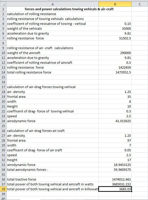
total aerodynamic force =41.01+18.94
= 59.960 N
total tractive force = 59.960+1473952.5
=1474012.461 N
total power drawn by both
pte=fte*v
1474012.461*2.5
=3685031.152 watts
total power in kw = 3685.03 kw
Here i have assumed the weight of towing vehicle as 35000 kg and i have taken aircraft as my airplane which is being towed by the towing vehicle. The weight is 290000 kg.
The other parameters i have assumed are
Coefficient for rolling resistance for towing vehicle =0.15
coefficient of rolling resistance for aircraft = 0.5
Coefficient of drag for towing vehicle = 0.015
coefficient of drag for aircraft = 0.05 (here it is low because first the effect of air will be on the vehicle and then it will affect the aircraft)
speed i have assumed here is 2.5m/s it will be low because the towing vehicle will not run at high speed while pushing/pulling the aircraft
Then i have simply calculated rolling resistance force and drag force for both towing vehicle and aircraft and i have summed up both to get the total force. So here the total force i got was 1474012.4 N
The total power in kW i got was 3685.03KW by multiplying Total force and velocity.
B. Develop the model for the calculated force and power using Simulink.
Now we create simulink model for above calculated force and power in the simulink models first i have create subsystem of rolling resistance force following parameter are puts into its , coefficients of rolling resistance , mass of gravity , mass of vehicals make products of such block with the blocks like constants , and products , display shows the value of force in N same subsystem of aerodynamic force is to be calculated are build while the puts parameter and used blocks like constants , square functions products and display which are connected with each other
following figure shows the simulink models which calculate total forces and power
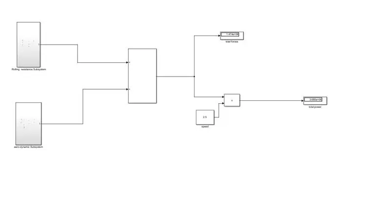
so now above simulink models by openning the subsystem of rolling resisatnce force where rolling resistance are calculated for both aircraft and towing vehicals and given outputs to additions block calculate total rolling resistance force and taken display blocks to shows value taken ouputs port of subsystem across the outputs of addition blocks
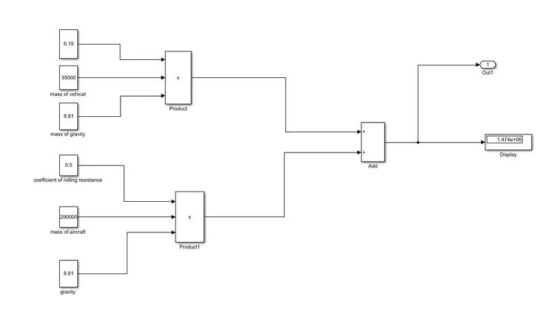
now we openning the subsystem of aeroidynamic force where aerodynamics are calculated for both aircraft and towing vehicals and given outputs to additions block calculate total aerodynamic force and taken display blocks to shows value taken ouputs port of subsystem across the outputs of addition blocks .
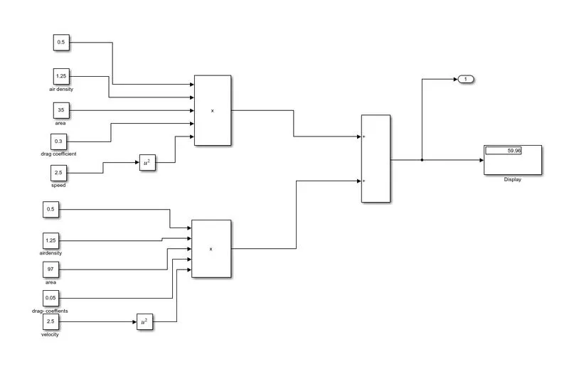
from the simulink model we have created we calculated the value of total power and force . which are displaying the value in the display blocks .
7. A. Design an electric powertrain with type of motor, it’s power rating, and energy requirement to fulfill aircraft towing application in Simulink. Estimate the duty cycle range to control the aircraft speed from zero to highest. Make all required assumptions. Prepare a table of assumed parameters. Draw a block diagram of powertrain.
(Hint :DC7 Block)
B. Also, Design the parameters in excel sheet.
Energy =power*time
=from above questions the power calculated is
power =3685.03 kw
time is assumed as 20 minutes which is converted into hours as 0.33 hrs
time t = 0.33 h
Now
energy = 3685.05 *0.33
energy = 1216.05 kwh
the energy required for 20 min above calculted power is 1216.05 kwh .
Now we have to calculate the input power to drive the duty cycle of the towing vehicle from the above question, those values are considered based on certain assumptions d towing vehicle
Duty cycle = Power output/Power input
Where the power input is to be calculated based upon the assumptions of the Motor spar
Input voltage = 700V
Input current = 600A
Now, Power input = Input voltage x Input current
Power input = 700× 600
Power input = 420000W
Power intput = 420KW
From the calculated values, duty cycle is,
Duty cycle = Power output/Power input
Duty cycle = 368.5/420
Duty Cycle = 0.87
% Duty cycle = 87%
The duty cycle required for towing the vehicle is 87%.
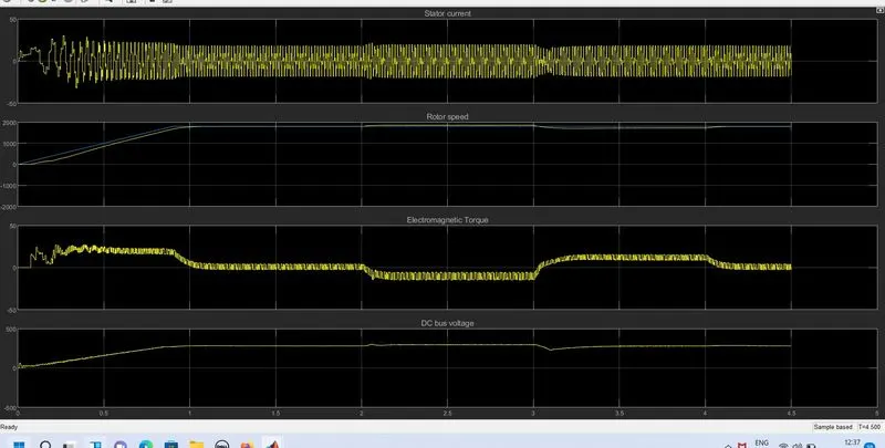
model of dc7 motor based
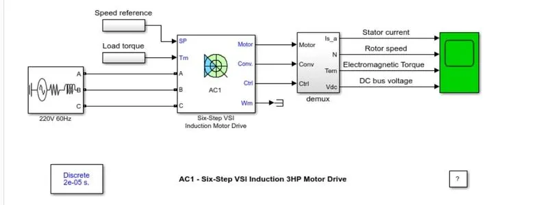
In above model ac to dc converter is used to convert ac voltage into dc supply by using converter .In above simulink model we supply the vtg 380 v ac to dc converter is used to convet into dc because dc supply required dc supply only the converter output is given to input of dc7 blocks which gives value to selector block the value of vtg current and speed are given to the scope blocks scope block gives the resultant plots .