Project-1: Powertrain for aircraft in runways
Part A:
1. Search and list out the total weight of various types of aircrafts.
2. Is there any difference between ground speed and air speed?
3. Why is it not recommended to use aircraft engine power to move it on the ground at Airport?
4. How an aircraft is pushed to runway when its ready to take off?
5. Learn about take off power, tyre design, rolling resistance, tyre pressure, and brake forces when landing.
Answers:
1: Weight is the force generated by the gravitational attraction of the earth on the airplane. Each part of the aircraft has a unique weight and mass, and for some problems, it is important to know the distribution. But for total aircraft maneuvering, we only need to be concerned with the total weight and the location of the center of gravity. The center of gravity is the average location of the mass of any object. An airplane is a combination of many parts; the wings, engines, fuselage, and tail, plus the payload and the fuel. Each part has a weight associated with it. An aircraft's gross weight is limited by several weight restrictions in order to avoid overloading its structure or to avoid unacceptable performance or handling qualities while in operation
- The aircraft gross weight (also known as the all-up weight and abbreviated AUW) is the total aircraft weight at any moment during the flight or ground operation. An aircraft's gross weight will decrease during a flight due to fuel and oil consumption. An aircraft's gross weight may also vary during a flight due to payload dropping or in-flight refueling. At the moment of releasing its brakes, the gross weight of an aircraft is equal to its takeoff weight. During the flight, an aircraft's gross weight is referred to as the en-route weight or in-flight weight.
- Maximum design taxi weight: The maximum design taxi weight (also known as the maximum design ramp weight (MDRW)) is the maximum weight certificated for aircraft maneuvering on the ground (taxiing or towing) as limited by aircraft strength and airworthiness requirements.
- Maximum design takeoff weight: Is the maximum certificated design weight when the brakes are released for takeoff and is the greatest weight for which compliance with the relevant structural and engineering requirements has been demonstrated by the manufacturer.
- Maximum design landing weight: The maximum certificated design weight at which the aircraft meets the appropriate landing certification requirements. It generally depends on the landing gear strength or the landing impact loads on certain parts of the wing structure. The MDLW must not exceed the MDTOW. The maximum landing weight is typically designed for 10 feet per second (600 feet per minute) sink rate at touch down with no structural damage.
- Maximum design zero fuel weight: The maximum certificated design weight of the aircraft less all usable fuel and other specified usable agents (engine injection fluid, and other consumable propulsion agents). It is the maximum weight permitted before usable fuel and other specified usable fluids are loaded in specified sections of the airplane. The MDZFW is limited by strength and airworthiness requirements. At this weight, the subsequent addition of fuel will not result in the aircraft design strength being exceeded. The weight difference between the MDTOW and the MDZFW may be utilized only for the addition of fuel.
- Minimum flight weight: Minimum certificated weight for flight is limited by aircraft strength and airworthiness requirements.
| Aircraft | Empty weight | Max fuel weight | Max cargo weight | Gross takeoff weight |
| Antanov AN-225 | 628,000 lbs 285,000 kg | 661400 lbs 300000 kg | 417000 lbs 190000 kg | 1411000 lbs 640000 kg |
| Airbus A380-800 | 611,000 lbs 277,000 kg |
560,000 lbs 254,000 kg |
185,000 lbs 84,000 kg |
1,268,000 lbs 575,000 kg |
| Boeing 747-800 | 485,300 lbs 220,100 kg |
427,400 lbs 194,000 kg |
295,000 lbs 134,000 kg |
987,000 lbs 447,700 kg |
| Airbus A340-500 | 370,000 lbs 168,000 kg |
386,300 lbs 175,000 kg |
119,000 lbs 54,000 kg |
820,000 lbs 372,000 kg |
| Boeing 777-300ER | 370,000 lbs 168,000 kg | 320,800 lbs 145,500 kg | 148,000 lbs 67,100 kg |
776,000 lbs 352,000 kg |
| Embraer 190 | 63,500 lbs 28,800 kg |
28,600 lbs 13,000 kg |
28,800 lbs 13,100 kg |
106,000 lbs 48,000 kg |
| Gulfstream G650 | 54,000 lbs 24,500 kg | 48,200 lbs 21,900 kg | 6,500 lbs 3,000 kg |
100,000 lbs 45,200 kg |
| Bombardier Q400 | 39,300 lbs 17,800 kg |
11,700 lbs 5,300 kg |
18,700 lbs 8,500 kg |
62,000 lbs 28,000 kg |
| Learjet 75 | 13,900 lbs 6,300 kg | 6,060 lbs 2,750 kg |
2,900 lbs 1,300 kg |
21,500 lbs 9,700 kg |
| Cessna Citation CJ4 | 10,300 lbs 4,700 kg | 5,800 lbs 2,650 kg |
2,200 lbs 1,000 kg | 17,200 lbs 7,800 kg |
| Beechcraft King Air B100 | 7,100 lbs 3,200 kg | 3,200 lbs 1,450 kg |
4,150 lbs 1,900 kg |
12,000 lbs 5,400 kg |
| Diamond DA50 RG | 3,200 lbs 1,450 kg |
340 lbs 155 lbs |
1,250 lbs 560 kg |
4,400 lbs 2,000 kg |
| Sirrus SR22 | 2,250 lbs 1,000 kg | 485 lbs 220 kg |
950 lbs 430 kg |
3,600 lbs 1,630 kg |
2. Ground speed: It is referred to as the speed of an airplane with respect to the surface of the earth. Ground speed is measured using GPS.
Air speed: Airspeed is the vector difference between the ground speed and the wind speed. On a perfectly still day, the airspeed is equal to the ground speed. But if the wind is blowing in the same direction that the aircraft is moving, the airspeed will be less than the ground speed.
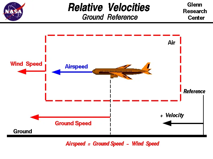
Difference between air speed and ground speed:
- Air speed determines whether there is enough airflow around an aircraft to make it fly.
- Ground speed determines how fast an aircraft will get to its destination.
- Both air speed and ground speed changes based on the wind component.
- If there is no wind then ground speed = air speed.
- Gravity is also considered important because speed of aircraft increases as it is descending.
- If the aircraft is flying in the same direction as the wind is blowing it experiances a tailwind and its ground speed is higher than its airspeed. If the wind is blowing against the diection of aircraft is travelling in the aircraft experiances headwind and its ground speed is lower than its airspeed.
3. Why is it not recommended to use aircraft engine power to move it on the ground at Airport?
- High engine thrust during maintenance activity can cause considerable damage to airplanes and other elements in the airport environment.
- For moving on ground, the air craft uses its own engine power called taxing.
- Many aircrafts are capable of moving backward using reverse thrust as a result the jet blash or prop wash might cause damage to terminal building or equipment.
- Engine close to ground may blow sand or debris.
- There is a risk of injury for the people who may be standing close to the aircraft.
- To save fuel it is not recommended to use aircraft engine to move it on airport.
- To avoid noise pollution for the passengers it is not reccommended to use aircraft to move in the airport.
4. How an aircraft is pushed to runway when its ready to take off?
- Airplanes can move forward by themselves on ground. They push themselves to the runway.
- It is also known as taxiing in which the aircraft moves on ground with its own power.
- It usually moves on wheels.
- By far the most common sight around the world's airports is the tug and a towbar. The towbars are connected to the axle of the aircraft's front landing gear and then to the front or rear of the Tug. Once connected, the driver of the Tug can easily maneuver the aircraft from the gate and out onto the taxiway.
- In case of towing the movement of large airplane along the airport or flight line is accomplised by a tow tractor. Sometime tow bars are used for moving which have small wheels.
- Tow bars may vary depending on the aircrafts. For aircrafts equipped with tail wheels are towed forward by attaching the tow bar to the main landing gear.
- A small vehicle is needed to push the large aircraft away from the terminal building.
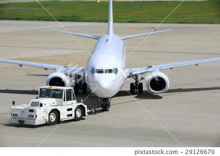
- Towing should be done carefully and a talented pilot should be inside the aircraft to operate the brakes.
- This due to safety considerations. This is done to keep the wind from damaging the flight controls while on the ground. Wind can slam flight controls (ailerons, rudder and elevators), doing damage while on the ground. Flight controls are designed to work with air flowing over them.
- After that the planes can apply a small amount of engine power to move forward.
5. Take off power : The amount of power that an engine is allowed to produce for a limited period of time for takeoff. The use of takeoff power is usually limited to 5 min for reciprocating engines and up to 2½ min for gas turbine engines. For light aircraft full power is is used during takeoff.
Tyre design: When it comes to safety, tyres are one of the most important components of aircraft. They help to absorb the shock of landing and provide cushioning. It also provides the necessary traction for braking and stopping of an aircraft. An aircraft tyre is designed to withstand extremely heavy loads while landing, take off, taxing, and parking. The number of wheels required for aircraft increases with the weight of the aircraft, as the weight of the aeroplane needs to be distributed more evenly. 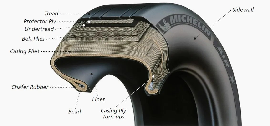
Carcass plies are used to form the tire. They are sometimes called casing plies. An aircraft tyre is constructed for the purpose it serves.
- They support the weight of an aircraft while it is on the ground.
- It also provides the necessary traction for braking and stopping of an aeroplane.
- Tyre also helps to absorb the shock of landing and provide cushioning the roughness of takeoff, roll-out, and taxi operations.
Rolling resistance: When taking off from a runway covered with slush, standing water or snow, the required take-off ground-run distance will be longer than on a dry runway. This is the result of the fact that slush, standing water and snow on the runway will generate a rolling resistance that increases the total resistance on the aircraft during the ground-run.
F= u(W-L)
Rolling resistance force will be the difference of weight of aircraft and lift multiplied by friction coefficient magnitude.
Tyre pressure: An aircraft tire or tyre is designed to withstand extremely heavy loads for short durations thus they operate at high pressure. The number of tires required for aircraft increases with the weight of the aircraft, as the weight of the airplane needs to be distributed more evenly. Aircraft tire tread patterns are designed to facilitate stability in high crosswind conditions, to channel water away to prevent hydroplaning, and for braking effect.
Brake forces when landing: Aircraft brakes stop a moving aircraft by converting its kinetic energy to heat energy by means of friction between rotating and stationary discs located in brake assemblies in the wheels. Brakes provide this critical stopping function during landings to enable airplanes to stop within the length of the runway. They also stop aircraft during rejected takeoff events, in which an attempted takeoff is canceled as the airplane is rolling down the runway before it lifts off from the ground due to engine failure, tire blowout, other system failure or direction from air traffic control. Average acceleration approach used to estimate the take off roll dv/dt= -T-D-F/m.
Brake force = mass * deceleration
where T is the thrust of propulsion system, D is the aerodynamic drag of vehicle, F is the rolling resistance friction.
PART B :
6. A. With necessary assumptions, calculate the force and power required to push / pull an aircraft by a towing vehicle.
A: For push or pull of an aircraft the force acting on it will be the rolling resistance force and air drag force
We know the equations for Rolling resistance force Frr= μrr*m*g
Aerodynamic force Fad= 0.5*ρ*A*Cd*V^2
Assuming the values of parameters for calculation of forces.
Consider the case of Antanov AN-225 aircraft.
Calculation of forces:
- Mass of aircraft = 285,000 kg
- Mass of towing vehicle= 50000 kg
- Gravitational constant= 9.8 m/s^2
- Coefficient of rolling resistance μrr= 0.02
- Velocity in Kmph= 20
- Velocity in m/s = 20*5/18=5.555 m/s
- Air drag density=1.225 kg/m^3
- Area=335 m^2
- Drag coefficient Cd=0.15
- Rolling resistance force Frr= μrr*m*g
= 0.02*(285000+50000)*9.8
= 65660 N
- Aerodynamic force Fad= 0.5*ρ*A*Cd*V^2
= 0.5*1.225*335*0.15*5.55^2
= 948.04 N
- Total tractive force = 65660+948.04=66608.04 N
Power calculation:
- Power = Total tractive force * Velocity
= (65660+948.04)*5.55/1000
Power required by the towing vehicle is calculated as = 369.67KW
Hence total tractive effort required by the towing vehicle is calculated as 66608 N and power required by the towing vehicle to push or pull an aircraft is 369.67KW.
B. Develop the model for the calculated force and power using Simulink.
A: A model is created using the simulink blocks to calculate the force and power required by the towing vehicle to move the aircraft.
Blocks used are: Constant blocks in which assumed variable values are provided, product block to find the multiplied value, add block to find total sum of forces, square block to get speed square value as per the equation and a display block to indicate the result numericals.
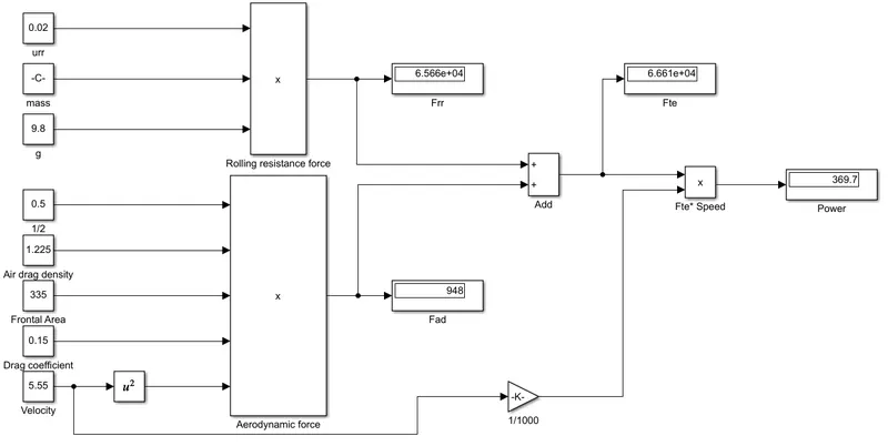
https://drive.google.com/file/d/1Md8ryEwzmKNRsOG4lYyQBVctMwEV0jQ7/view?usp=sharing
7. A. Design an electric powertrain with type of motor, it’s power rating, and energy requirement to fulfill aircraft towing application in Simulink. Estimate the duty cycle range to control the aircraft speed from zero to highest. Make all required assumptions. Prepare a table of assumed parameters. Draw a block diagram of powertrain.
(Hint :DC7 Block)
A: From the above question the force and power required by the towing vehicle to move the aircraft is already calculated. So energy required by the vehicle can be calculated using the equation,
Energy = Power*time
Here time is assumed to as 20 minutes = 0.33h when converted to hours.
E = 369.67*0.33
E = 121.99KWh
Next input power to drive the duty cycle of towing vehicle is calculated.
Duty cycle = Power output/ Power input
Output power is taken as same as the above question.
For calculating the input power , some assumptions are made regarding the values of input voltage and input current of selected motor specifications.
Let input voltage = 650 V
Let input current = 600 A
Power input = Input voltage *Input current
Pin = 650*600 = 390KW
Duty cycle = Power output / Power input
= 369.67 / 390
D = 0.94
Assumed values are given in the table below;
| Parameter | Value taken |
| Frontal area | 335 m^2 |
| Air density | 1.225kg/m^3 |
| Rolling resistance coefficient | 0.02 |
| Velocity | 5.55 m/s |
| Drag coefficient | 0.15 |
| Input Current | 600 A |
| Input Voltage | 650 V |
| Time | 20 min |
Block diagram of power train:
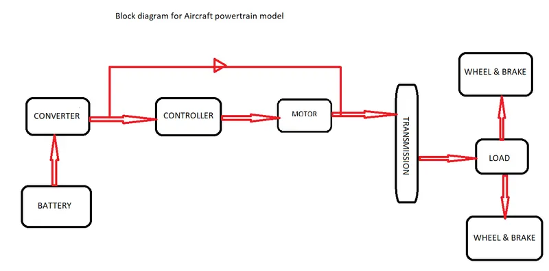
Here battery source is connected to converter to give the required dc supply voltage. The converter performs required conversion of input dc and gives it to the controller. The controller block controls the parameters of motor for its optimal performance. Output of motor is given to the transmission system where it is linked to the wheels and brakes and to the load.
Design of electric powertrain using DC_7 block simulink model:
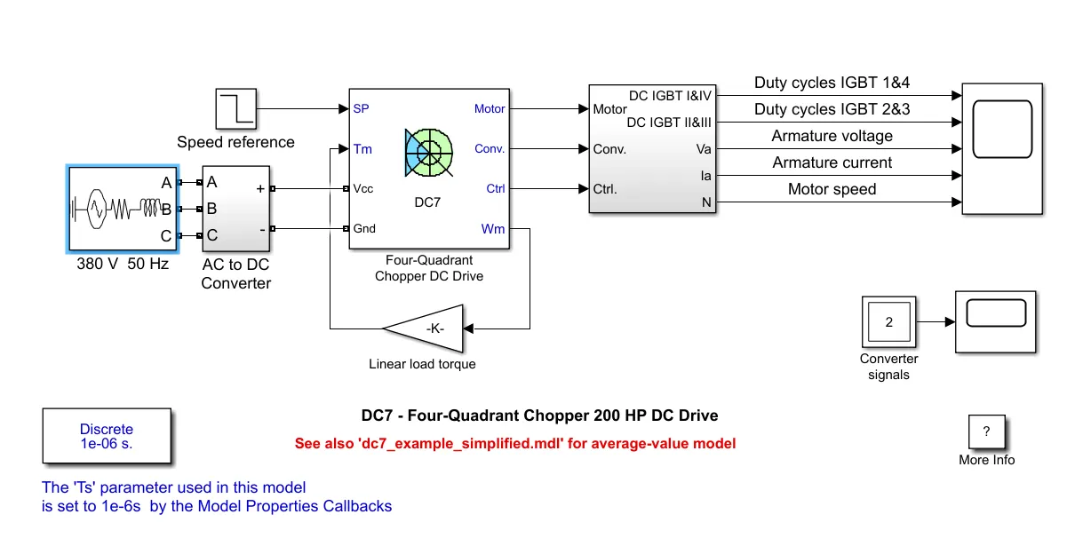
In the above given DC7 model the input voltage is given as 380V. AC to DC converter is used to convert the given AC supply voltage into DC voltage. Converter output gives values to the DC7 block which gives the values to selector block. From the selector block the value of voltage, speed, current and duty cycles are given to the scope block. Scope gives resultant output plots.
Output waveforms:
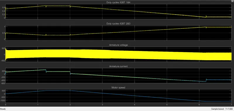
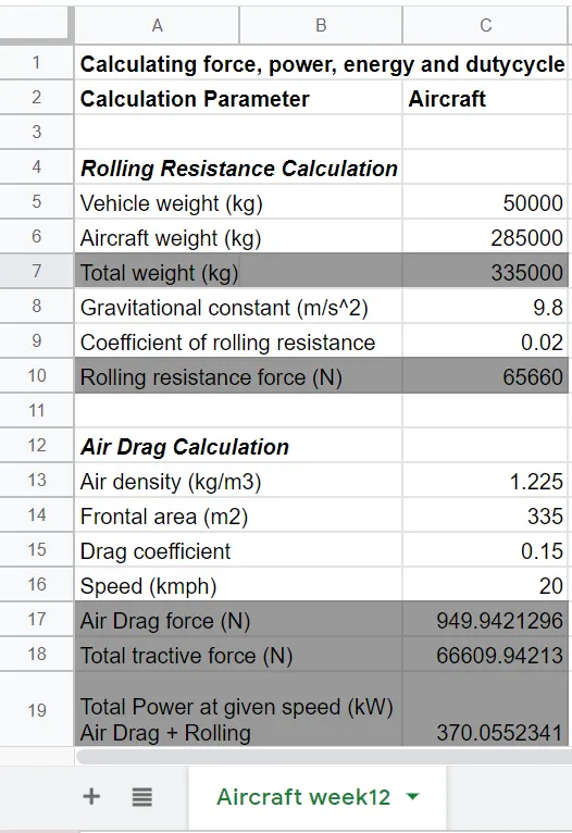
B. Also, Design the parameters in excel sheet.
A: The above solved question is again calculated and verified using excel sheet calculator.
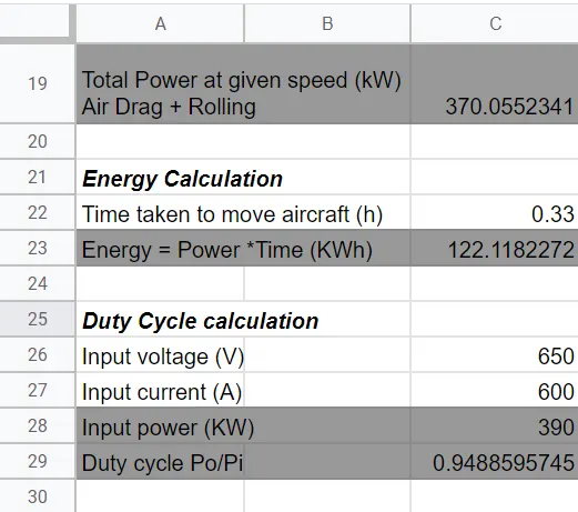
https://docs.google.com/spreadsheets/d/1ooirIPd7uIsIlq2IjFAxbRS3CNJdNQWsa2V1sBIEDzw/edit?usp=sharing