Project-1: Powertrain for aircraft in runways
Part A:
1. Search and list out the total weight of various types of aircraft.
ans)
Airplanes are one of the largest, and heaviest, mobile objects in our world today.
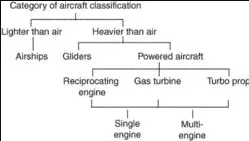
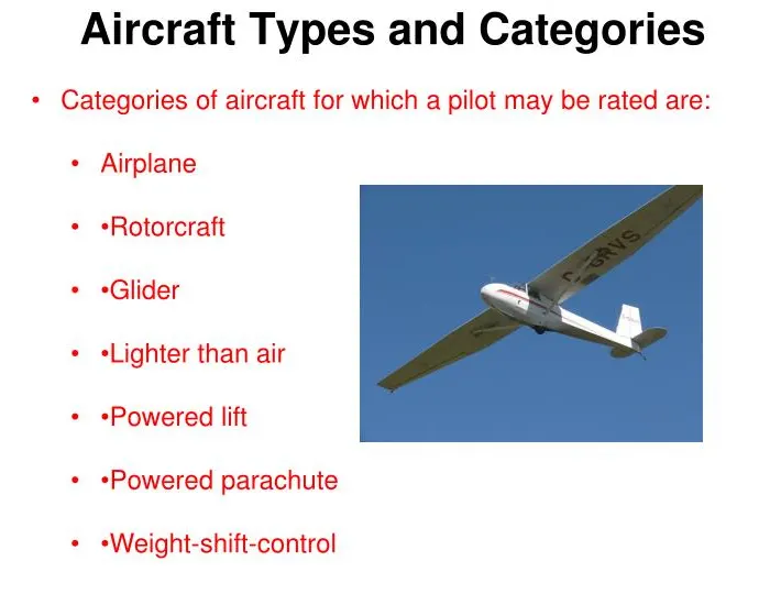
How Much Does An Airplane Weight?
Airplanes can weigh between 2,000 pounds (907 kg) for a small Cessna, to upwards of over 1 million pounds (453,592 kg) during takeoff for an Airbus A380.
They weigh so much that they need well-designed runways to handle their massive weights.
That is exactly why airplanes cannot land just anywhere.
How Much Does The Boeing 747 Weight?
The average-sized Boeing 747, with passengers, weighs between 735,000 pounds (333,400 kg) and 970,000 pounds (439,985 kg)
That’s about the weight of 5 space shuttles!
Maximum Takeoff Weights Of Different Planes
- Airbus A330-800F – 1,117,882 pounds (507,063 kg)
- Boeing 747-400 – 875,014 pounds (396,900 kg)
- Lockheed C-5 Galaxy – 839,961 pounds (381,000 kg)
- McDonnel Douglas MD-11 – 602,523 pounds (273,300 kg)
- Boeing 767-400ER – 449,743 pounds (204,000 kg)
- Concorde – 407,855 pounds (185,000 kg)
- Boeing 727-100 – 159,835 pounds (72,500 kg)
How Much Does Jet Fuel Weight?
The weight of aviation fuel depends on the type of fuel. One of the most common is JP-5 which weighs 6.8 pounds per U.S gallon.
Usually, an average airplane like the Boeing 747 burns one gallon of fuel every second. So, in a 10-hour trip, the plane burns approximately 36,000 gallons of fuel.
It can take an hour just to fill one of these airplanes up.
The heaviest airplane in existence today is the Antonov An-225. It carries a maximum takeoff weight of 1,280,000 pounds (580,598 kg).
That is just a bit heavier than the largest passenger-carrying airplane, the Airbus A380. It comes in a lighter 1,265,000 pounds (573,794 kg) when fully loaded
2. Is there any difference between ground speed and airspeed?
ans)
difference between ground speed and airspeed:
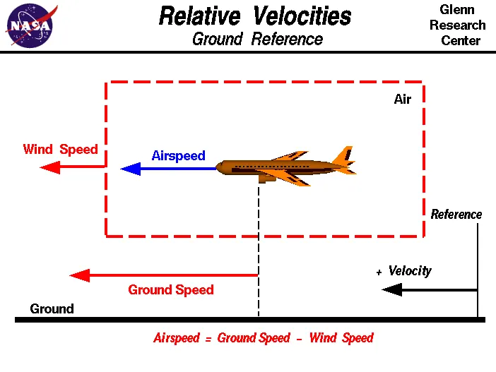
here are two different types of speed when talking about airplanes – ground speed and airspeed. While ground speed is the airplane’s speed relative to the surface of the Earth, airspeed – at least true airspeed – is its speed relative to the air it is flying in. True airspeed is simply the speed at which an aircraft is moving relative to the air it is flying in. As such, it’s also the speed at which the air is flowing around the aircraft’s wings. Ground speed, on the other hand, is the aircraft’s speed relative to the ground. One thing that should be noted here is that it’s it's horizontal rather than vertical speed – an aircraft climbing completely vertically would have a ground speed of zero. In other words, while airspeed is what determines whether there is enough airflow around an aircraft to make it fly, ground speed is what determines how fast an aircraft will get to its destination.
3. Why is it not recommended to use aircraft engine power to move it on the ground at the Airport?
ans)
There are some reasons not to use aircraft engine power to move it on the ground at the airport as given below:
1) A Very huge amount of fuel is consumed by the engine. So the taxing fuel can be saved for the aircraft's flight
2) Aircraft engine creates very high noise which is not good.
3) It will cause very injuries and damage to the nearby population or people if pilots lose control.
4. How an aircraft is pushed to the runway when it's ready to take off?
ans)
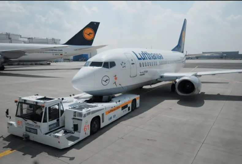
A so-called pushback truck reverses the aircraft into taxiing position, pushing it with a towbar attached to the nose-wheel strut. Or, in the most modern versions, by actually lifting the wheel. The aircraft taxis to the runway to depart at the agreed time.
5. Learn about take-off power, tire design, rolling resistance, tire pressure, and brake forces when landing.
ans)
take-off power:
take‑off includes the ground run from zero ground speed to the point where the wheels leave the ground, plus the distance required to clear a 50-foot obstacle. The distance over the ground for all of the above is computed at maximum gross weight at sea level standard conditions. The “worst-case” condition is often also calculated for a hot day at a high altitude (100ºF in Denver).
We will concern ourselves only with the ground run portion of the take‑off run, knowing that we can find the distance to clear a 50-foot obstacle from our climb equations. That climb would be calculated for the maximum angle of climb conditions.
The first step in the calculation of the ground run needed for take‑off is an examination of the forces on the aircraft. In addition to the lift, drag, thrust, and weight, we must now consider the ground friction and the “Resultant” force of the ground in supporting all or part of the weight of the aircraft. These are shown in the figure below. The coefficient of friction will depend on the ground surface and braking friction.
A summation of the vertical forces in Figure 7.1 gives
L + R ‑ W = 0
or
R = W ‑ L
Summing the horizontal forces gives
T−D−μR=mdV/dt">T−D−μR=mdV/dtT−D−μR=mdV/dt
Note that in the above relation we have, for the first time, an acceleration. These forces change as the aircraft accelerates from rest to take‑off speed.
Combining the two equations above we have a single relation
T−D−μ(W−L)=[W/g][dV/dt]">T−D−μ(W−L)=[W/g][dV/dt]T−D−μ(W−L)=[W/g][dV/dt]
which can be rearranged to give
g[(T/W)−μ]−(g/W)[D−μL]=dV/dt">g[(T/W)−μ]−(g/W)[D−μL]=dV/dtg[(T/W)−μ]−(g/W)[D−μL]=dV/dt
Our desire is to integrate this or a related equation to get the time and distance needed for the take‑off ground run. To do this we must first account for the dependence of both lift and drag on velocity. This gives
dV/dt=g[(T/W)−μ]−(g/W)(1/2)ρV2S[CD−μCLg],">dV/dt=g[(T/W)−μ]−(g/W)(1/2)ρV2S[CD−μCLg],dV/dt=g[(T/W)−μ]−(g/W)(1/2)ρV2S[CD−μCLg],
where CLg denotes the lift coefficient during the takeoff or landing ground run and not that in flight or at the point of takeoff or touchdown itself.
The above equation still contains thrust and weight, both of which may well change during the take‑off ground run. Thrust is known to be a function of velocity, however, the weight will be a function of the rate of fuel use (specific fuel consumption) and will be a function of time rather than speed. In order to keep our analysis relatively simple, we will consider the weight change during the take‑off roll to be negligible and treat weight as a constant in the equation. We will use the thrust model which we derived from the Momentum Equation in Chapter 2,
T = T0 -aV2
In this equation T0 is the thrust at zero velocity or the “static thrust”, a is a constant (which could be zero) and T is the thrust at any speed. Substituting this model for a thrust into our acceleration equation gives:
dV/dt=g[(T0/W)−μ]−(g/W){(1/2)ρS[CD−μCLg]+a}V2">dV/dt=g[(T0/W)−μ]−(g/W){(1/2)ρS[CD−μCLg]+a}V2dV/dt=g[(T0/W)−μ]−(g/W){(1/2)ρS[CD−μCLg]+a}V2
It should be noted that the velocity in this equation is the airspeed and not the speed relative to the ground. When we look at the take‑off distance we will have to be concerned with both the ground speed and the airspeed. The simplest case will be when there is no ground wind; ie, when the airspeed and ground speed is equal.
In the above relation, all of the terms in brackets and parentheses are essentially constant for a given aircraft at a given runway altitude and for a given runway surface. The lift coefficient is given the special designation of CLg to denote that it is the value for the ground run only. In a normal take‑off roll, the airplane accelerates to a pre-determined speed and then “rotates” to a higher angle of attack which will produce enough lift to result in lift‑off at that speed. Hence, the ground run lift coefficient will probably not be the same as the take‑off lift coefficient. The drag coefficient could be similarly subscripted; however, since CD is a function of CL and will subsequently be written in that manner, this will not be done at this point.
Since most of the terms in the equation can be treated as constants the equation can be simplified as follows:
dV/dt = A – BV2 ,
where
A=g{(T0/W)−μ}">A=g{(T0/W)−μ}A=g{(T0/W)−μ}
and
B=(g/W){(1/2)ρS[CD−μCLg]+a}">B=(g/W){(1/2)ρS[CD−μCLg]+a}B=(g/W){(1/2)ρS[CD−μCLg]+a}
This acceleration relationship can be integrated to obtain the time for the ground run of take‑off.
∫t1t2dt=∫1v2dVA−BV2">∫t2t1dt=∫v21dVA−BV2∫t1t2dt=∫1v2dVA−BV2
Assuming that the airplane starts the take‑off run from rest and that there is no ground wind and that the upper limit is the take‑off velocity VTO, we have
t=1ABtanh−1(VTOBA)=time for take-off.">t=1√ABtanh−1(VTO√BA)=time for take – off.t=1ABtanh−1(VTOBA)=time for take-off.
NOTE: This may be the first time that the reader has ever seen an inverse hyperbolic tangent. What should follow is a frantic search of your calculator to see if there is any such key or combination of keys along with an equally harried check of the indices of high school and college trig and calculus texts to see just what the heck this thing is. Waiting to figure this out during a test could result in considerable embarrassment.
A question that should be considered here is “What is a good value for the take‑off speed?”
The very lowest speed at which the airplane can possibly lift off of the ground is the stall speed for straight and level flight at the runway altitude. It is, however, not safe to attempt takeoff at this minimum speed with the airplane right on the verge of a stall. A somewhat higher than stall speed will give a margin of safety which will allow take‑off at a fairly low speed without the risk of stall due to unexpected gusts or similar problems. Commonly used values for take-off speed range from 10 to 20 percent higher than straight and level stall speed.
tire design:
Carcass plies are used to form the tire. They are sometimes called casing plies. An aircraft tire is constructed for the purpose it serves.
- They support the weight of an aircraft while it is on the ground.
- It also provides the necessary traction for the braking and stopping of an airplane.
- Tyre also helps to absorb the shock of landing and provides cushioning for the roughness of takeoff, roll-out, and taxi operations.
Unlike an automobile or truck tire, it does not have to carry a load for a long period of continuous operation. However, an aircraft tire absorbs the high impact loads of landing, and also it’s operating at high speeds for a short time when required.
When it comes to safety, tires are one of the most important components of aircraft. They help to absorb the shock of landing and provide cushioning. It also provides the necessary traction for braking and stopping an aircraft.
An aircraft tire is designed to withstand extremely heavy loads while landing, taking off, taxing, and parking. The number of wheels required for aircraft increases with the weight of the aircraft, as the weight of the airplane needs to be distributed more evenly.
rolling resistance:
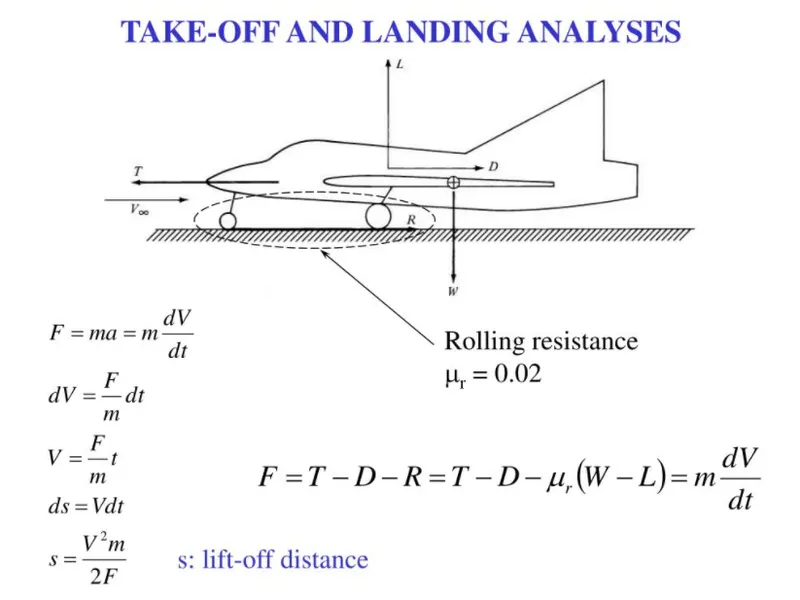
When a tire of aircraft is rolling on the road the mechanical energy is converted into heat as a result of rolling resistance. Rolling resistance is the effort required to keep the tire rolling.
In the below figure formula and better idea about rolling resistance is shown.
tire pressure:
Tire pressure table is shown below.
| Size | Ply Rating | Max. Load (per tire) | Unloaded Inflation (psi) |
| 10/350-4 | 4 | 460 | 60 |
| 12.5-4.5 | 10 | 1800 | 75 |
| 18-5.5 | 8 | 3050 | 105 |
| 22/800-8 | 6 | 2500 | 40 |
| 27" SC | 10 | 5500 | 50 |
| 29/1100-10 | 10 | 7070 | 60 |
| 280/250-4 | 4 | 395 | 60 |
| 5.00-4, 500x4, 5.00x4 | 6 | 1200 | 55 |
| 5.00-4, 500x4, 5.00x4 | 14 | 2550 | 115 |
| 5.00-5, 500x5, 5.00x5 | 4 | 800 | 31 |
| 5.00-5, 500x5, 5.00x5 | 6 | 1285 | 50 |
| 5.00-5, 500x5, 5.00x5 | 10 | 2150 | 88 |
| 6.00-6, 600x6, 6.00x6 | 4 | 1150 | 29 |
| 6.00-6, 600x6, 6.00x6 | 6 | 1750 | 42 |
| 6.00-6, 600x6, 6.00x6 | 8 | 2350 | 55 |
| 7.00-6, 700x6, 7.00x6 | 6 | 1900 | 38 |
| 7.00-6, 700x6, 7.00x6 | 8 | 2550 | 54 |
| 8.00-4, 800x4, 8.00x4 | 4 | 1100 | 24 |
| 8.00-6, 800x6, 8.00x6 | 4 | 1350 | 23 |
| 8.00-6, 800x6, 8.00x6 | 6 | 2050 | 35 |
| 8.00-6, 800x6, 8.00x6 | 8 | 2800 | 48 |
| 8.50-6, 850x6, 8.50x6 | 6 | 2275 | 30 |
| 9.00-6, 900x6, 9.00x6 | 10 | 4500 | 58 |
| 6.50-8, 650x8, 6.50x8 | 6 | 2300 | 51 |
| 6.50-8, 650x8, 6.50x8 | 8 | 3150 | 75 |
| 7.00-8, 700x8, 7.00x8 | 6 | 2400 | 46 |
| 6.50-10, 650x10, 6.50x10 | 6 | 2770 | 60 |
| 6.50-10, 650x10, 6.50x10 | 8 | 3750 | 80 |
| 6.50-10, 650x10, 6.50x10 | 10 | 4750 | 100 |
| 6.50-10, 650x10, 6.50x10 | 12 | 5750 | 120 |
| 8.50-10, 850x10, 8.50x10 | 6 | 3250 | 41 |
| 8.50-10, 850x10, 8.50x10 | 8 | 4400 | 55 |
| 8.50-10, 850x10, 8.50x10 | 10 | 5500 | 70 |
| 11.00-12, 1100x12, 11.00x12 | 8 | 6300 | 45 |
| 11.00-12, 1100x12, 11.00x12 | 10 | 8200 | 60 |
| 750-10 | 6 | 3000 | 46 |
| 890-12.50 | 6 | 4300 | 50 |
brake forces when landing:
Aircraft brakes stop a moving aircraft by converting its kinetic energy to heat energy by means of friction between rotating and stationary discs located in brake assemblies in the wheels.

A brake assembly on a Boeing 737NG main landing gear, visible after removal of one of the wheels. Source: SKYbrary (Click image to enlarge)
Brakes provide this critical stopping function during landings to enable airplanes to stop within the length of the runway. They also stop aircraft during rejected takeoff events, in which an attempted takeoff is canceled as the airplane is rolling down the runway before it lifts off from the ground due to engine failure, tire blowout, other system failures, or direction from air traffic control.
Aircraft brakes also prevent the motion of the aircraft when it is parked, limit its speed during taxiing, and can even help steer the aircraft on the ground by applying different levels of braking force to the left- and right-side brakes.
Aircraft brakes work in conjunction with other brake mechanisms such as thrust reversers, air brakes, and spoilers. Thrust reversers are surfaces that are deployed into the path of the jet blast from the engines to redirect propulsive thrust in a direction that opposes the motion of the aircraft. Air brakes and spoilers are flight control surfaces that create additional aerodynamic drag when deployed into the path of air flowing around the aircraft.
How aircraft brakes work:
The most common type of brake used on aircraft is the disc brake. Disc brakes function by exploiting friction between rotating and stationary discs inside the brake.
Upon receiving a command signal to brake — from the pilot depressing a foot pedal or from the auto brake system — actuators in the brake move a piston to squeeze the discs together, generating a frictional force that slows the rotation of the wheel. The friction between the discs generates heat as the aircraft’s kinetic energy is converted to heat energy. In this function, the brakes act as a heat sink, absorbing tremendous amounts of heat as the aircraft sheds kinetic energy. During RTO stops, the temperature of carbon disc brakes can exceed 1,800° C. 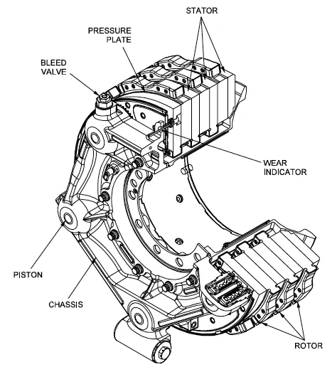
The discs are mounted on a carrier assembly consisting of a torque tube, which resists and transmits brake torque to the landing gear structure. Sandwiched together between the carrier assembly housing and a backing plate, the discs are arranged in an alternating pattern of rotors and stators. Notch and groove geometry around the circumference of each rotor fits into the corresponding geometry in the wheel, keying the rotors to the wheel so that they rotate with it. The stators are keyed to the torque tube and are thus held stationary since the torque tube is connected to the axle and landing gear structure.
Cylindrical spaces within the carrier assembly hold actuator pistons. Braking occurs as piston force squeezes the discs together.
During each application of the brakes, the disc material is worn away by frictional forces. A wear indicator in the form of a pin that protrudes out of the carrier assembly indicates the thickness of the stack of discs. Over hundreds of brake applications, the material wears away and discs become thinner, requiring replacement following periodic maintenance intervals.
Part B:
6.
A. With necessary assumptions, calculate the force and power required to push/pull an aircraft by a towing vehicle.
ans)
the force and power required to push or pull an aircraft by towing a vehicle is aerodynamic force and rolling resistance force.
1) Rolling resistance force:
we know the Equation for rolling resistance force is given below.
F = μrr*m*g......(1)
where F= rolling resistance force
μrr = rolling resistance coefficient 0.01
m= mass of the body
g=9.81 m/s^2
2) Aerodynamic force:
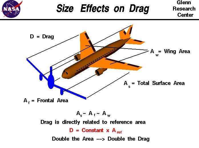
It is the force opposing the motion of the body. The air resists the motion of the aircraft and the resistance force is called drag. Drag is directed along and opposed to the flight direction. Like lift, there are many factors that affect the magnitude of the drag force including the shape of the aircraft, the "stickiness" of the air, and the velocity of the aircraft. This backward push is the induced drag. Technically speaking change in the vector direction of lift of the aircraft results in the formation of this type of drag. Other types of induced drag are due to a mixture of airflow above and below the wing. The airflow mixes at the tips of the aircraft.
Fd= 0.5* rho*v^2*Cd*A.....(2)
where
Fd= air drag force
rho = density of the air
v = flow velocity relative to the object
Cd = drag coefficient
A = reference area
Now let's take assumptions,
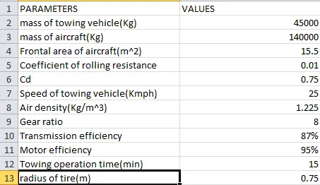
mass of towing vehicle = 45000 kg
mass of aircraft = 140000 kg
total mass M = 140000 + 45000 =185000 kg
the frontal area of aircraft A = 15.5 m^2
speed of towing vehicle v = 25 kmph = 25*1000/3600 = 6.9445 m/s^2
Cd = 0.75
rho = 1.225 kg/m^3
Now calculating Air drag force and rolling resistance force
F = 0.01*9.81*185000 = 18148.5 N
Fd = 0.5*0.75*1.225*15.5*6.9445*6.9445 = 343.384 N
Now calculating the total force required to push/pull an aircraft by a towing vehicle Ft = 18148.5 + 343.384 = 18491.8848 N
calculating power P = Ft*v = 18491.8848 * 6.9445 = 128.416 kW.
B. Develop the model for the calculated force and power using Simulink.
ans)
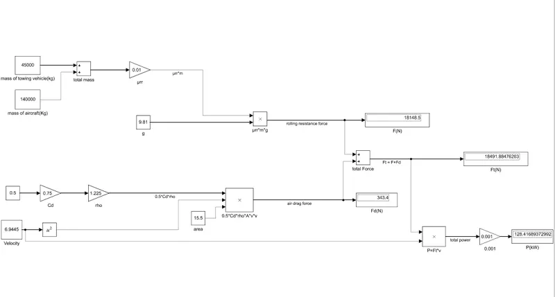
The model for the calculated force and power using Simulink.
Take the block as shown below and give them the name, and value as shown below, and arrange that as shown below.
In-display block changes Numeric display format to long so that will show after decimal values.
7.
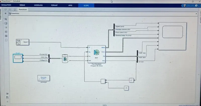
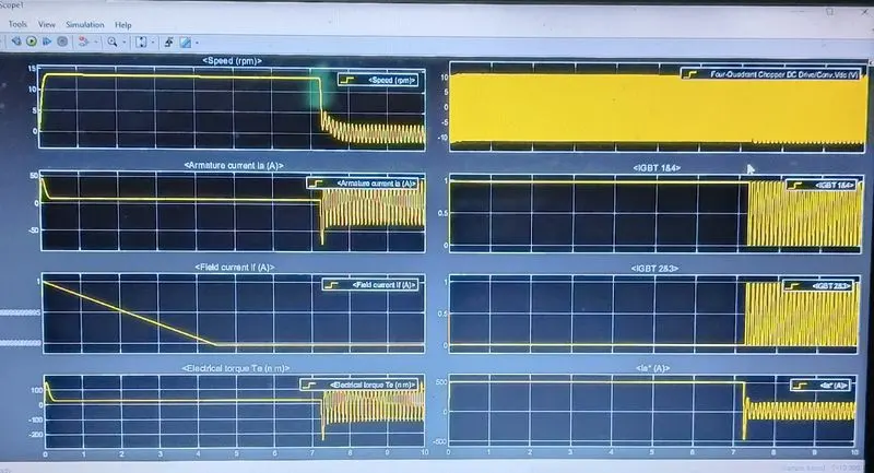
A. Design an electric powertrain with the type of motor, its power rating, and energy requirement to fulfill aircraft towing applications in Simulink. Estimate the duty cycle range to control the aircraft speed from zero to highest. Make all required assumptions. Prepare a table of assumed parameters. Draw a block diagram of the powertrain. (Hint: DC7 Block)
ans)
block diagram of the powertrain:
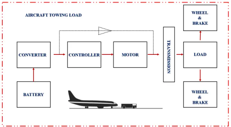
it is based on the calculation done in question 6.
total force required to push/pull an aircraft by a towing vehicle Ft = 18148.5 + 343.384 = 18491.8848 N = 18.491KN
total power P = Ft*v = 18491.8848 * 6.9445 = 128.416 kW.
let us assume,
the radius of the tire r = 0.75m.
gear ratio = 8
transmission efficiency = 87%
motor efficiency = 95%
operation time =15min = 0.25hr
battery capacity(rated power)=220kW
then,
The torque required to wheel Tw = Ft * r=18.491*0.75=13.868 kNm
So motor torque = Tw/gear ratio = 13.868/8=1.733kNm
and similarly, the total power required by the motor considering all efficiencies Pt = 128.416 /0.87*0.95=155.373 kW.
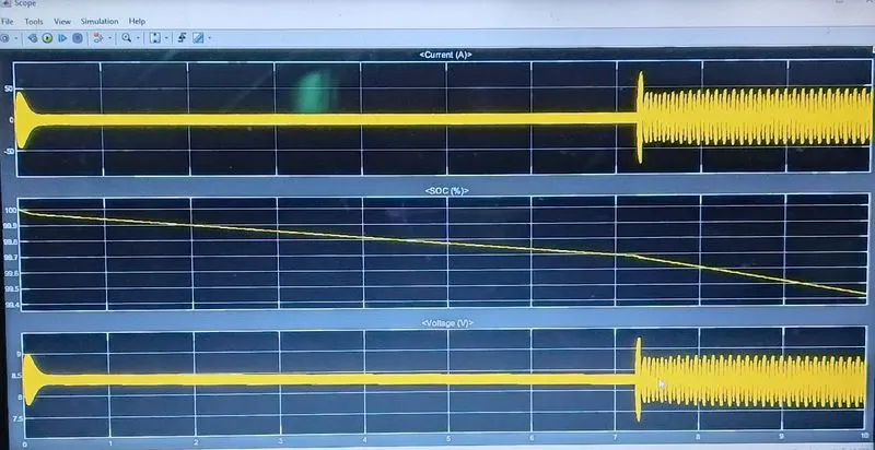
Total energy consumed = Pt*0.25=38.843 kWh.
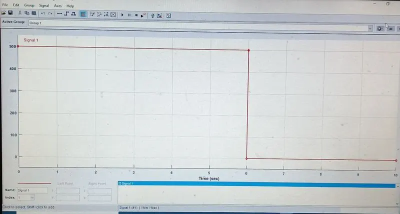
duty cycle = Pt/rated power = 155.373/220 = 0.70
so the controller will be able to provide a duty cycle range from 0 to 70% in order to control the towing vehicle speed.
B. Also, Design the parameters in an excel sheet.
ans)