Final Project: Design of an Electric Vehicle
Create a MATLAB model of electric car which uses a battery and a DC motor. Choose suitable blocks from Powertrain block set. Prepare a report about your model including following:
Objectives:
- System level configurations
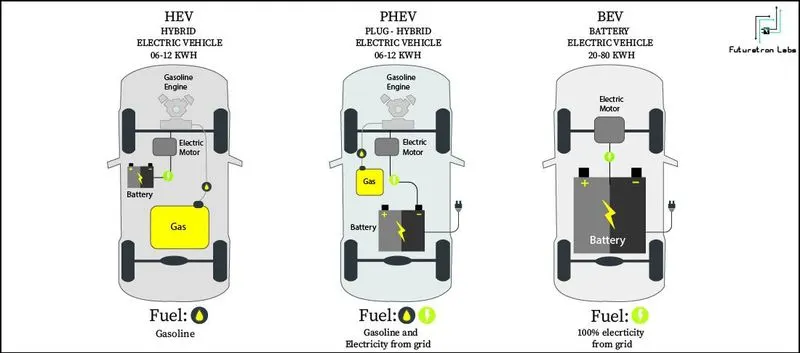
Motor
The motor converts electric energy into kinetic energy that moves the wheels. the EV powertrain is smaller than the engine, thus providing lots of additional space for efficient vehicle design. The motor is also in part an electric generator―it converts the kinetic energy generated while in neutral gear into electric energy saved to the battery. The same energy-saving idea applies when the car is reducing its speed, culminating in the so-called “regenerative braking system.”
Battery
The battery stores electrical energy and is the equivalent of a fuel tank in an internal combustion engine. The maximum driving distance of an EV is often determined by the battery capacity―the higher the capacity, the higher the driving distance. In that light, increasing the capacity may seem an obvious choice, since high driving distance reduces the annoying need for frequent stops at charging stations. But the choice actually isn’t so obvious, because the battery’s size and weight also have large implications on vehicle performance. The larger and heavier battery takes away from cabin/storage space and worsens the energy efficiency and fuel economy. The best way to optimize performance, then, is to maximize the battery’s energy density―that is, having a small, lightweight battery that stores as much electric energy as possible.
On-board Charger (OBC)
The On-board Charger (OBC) is used to convert Alternating Current (AC) from slow chargers or portable chargers used on home outlets into Direct Current(DC). This may make the OBC look similar to the traditional inverter, but they differ crucially in function; the OBC is for charging, and the inverter is for acceleration/deceleration. Incidentally, the OBC is not needed in fast-charging, since fast chargers already supply the electricity in direct current.
Electric Power Control Unit (EPCU)
The Electric Power Control Unit (EPCU) is an efficient integration of nearly all devices that control the flow of the electric power in the vehicle. It consists of the inverter, the Low voltage DC-DC Converter (LDC), and the Vehicle Control Unit (VCU).
Inverter
The inverter converts the battery’s DC into AC, which then is used to control the motor speed. The device is responsible for executing acceleration and deceleration, so it serves a crucial part in maximizing the EV’s drivability.
Low voltage DC-DC Converter
The LDC converts the high voltage electricity from the EV’s high-voltage battery into low-voltage(12V) and supplies it to the vehicle’s various electronic systems. All electronic systems in the EV use electricity in low voltage, so the high voltage in the battery must be converted first to be useful for these systems.
Vehicle Control Unit
As the control tower of all electric power control systems in the vehicle, The VCU is arguably the most important component of the EPCU. It oversees nearly all the vehicle’s power control mechanisms, including the motor control, regenerative braking control, A/C load management, and power supply for the electronic systems.
- Model parameters
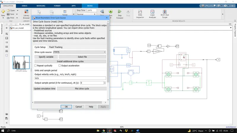
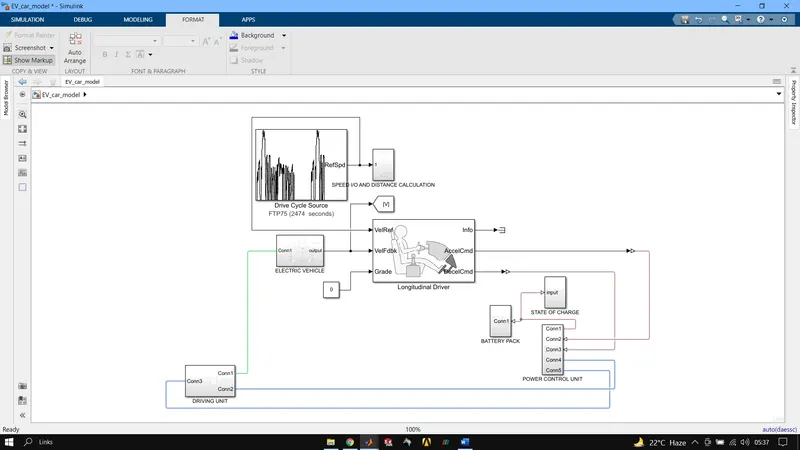
DRIVE CYCLE SOURCE BLOCK Generates a standard or user-specified longitudinal drive cycle. The block output is the vehicle longitudinal speed.
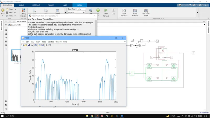
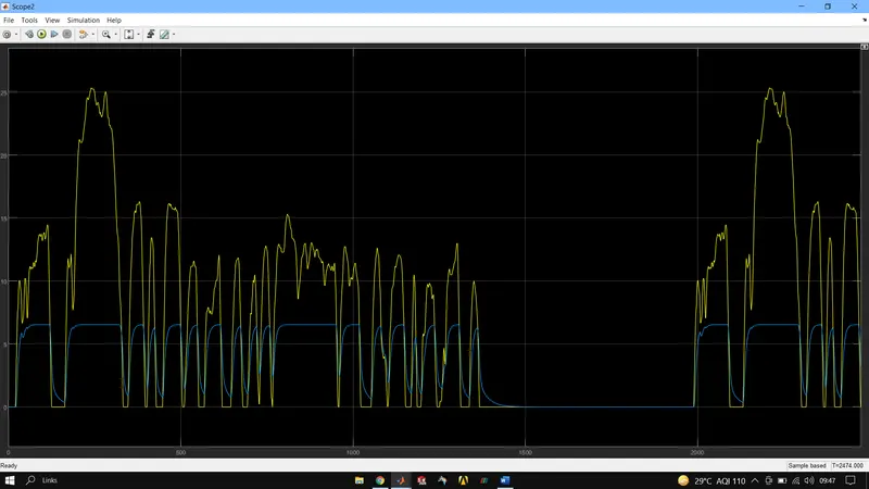
FTP75 is used as the drive cycle input, speed plot for the same is attached.
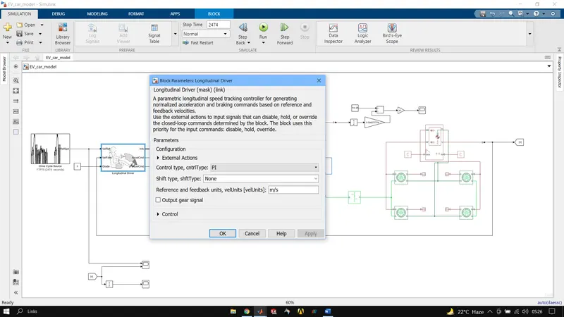
LONGITUDINAL DRIVER BLOCK, A parametric longitudinal speed tracking controller for generating normalized acceleration and braking commands based on reference and feedback velocities.
VelRef port is where input velocity from drive cycle data is fed, VelFed is the port where actual output velocity from the vehicle is feedback to the system which helps to reduce the error between input and output speeds. Grade port is used to input grade angle while Info port gives out bus signal for various parameters. AccelCmd and DecelCmd ports are used to fed acceleration and deceleration input values.
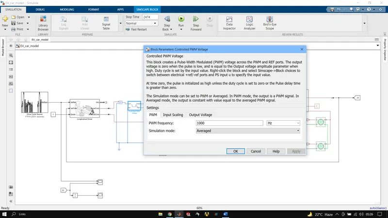
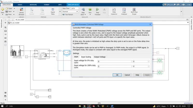
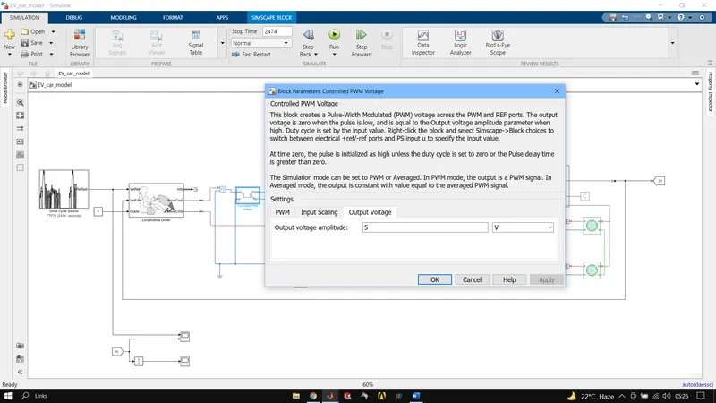
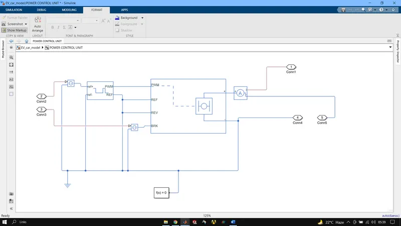
CONTROLLED PWM VOLTAGE BLOCK, this block creates a Pulse-Width Modulated (PWM) voltage across the PWM and REF ports. The output voltage is zero when the pulse is low, and is equal to the Output voltage amplitude parameter when high. Duty cycle is set by the input value.
It is used to provide proper pulse inputs to H-bridge circuit.
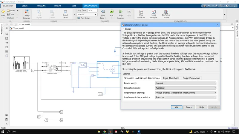
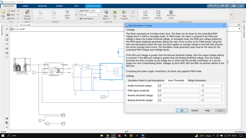
H-BRIDGE BLOCK, this block represents an H-bridge motor drive. The block can be driven by the Controlled PWM Voltage block in PWM or Averaged mode. In PWM mode, the motor is powered if the PWM port voltage is above the Enable threshold voltage. In Averaged mode, the PWM port voltage divided by the PWM signal amplitude parameter defines the ratio of the on-time to the PWM period. Using this ratio and assumptions about the load, the block applies an average voltage to the load that achieves the correct average load current.
REF port is the reference input which along with PWM port forms the pulse input for the circuit. REV port is for reversing of vehicle while BRK is for braking of vehicle whose input is given from controlled PWM voltage block.

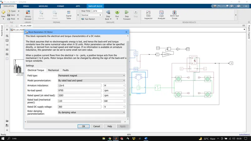
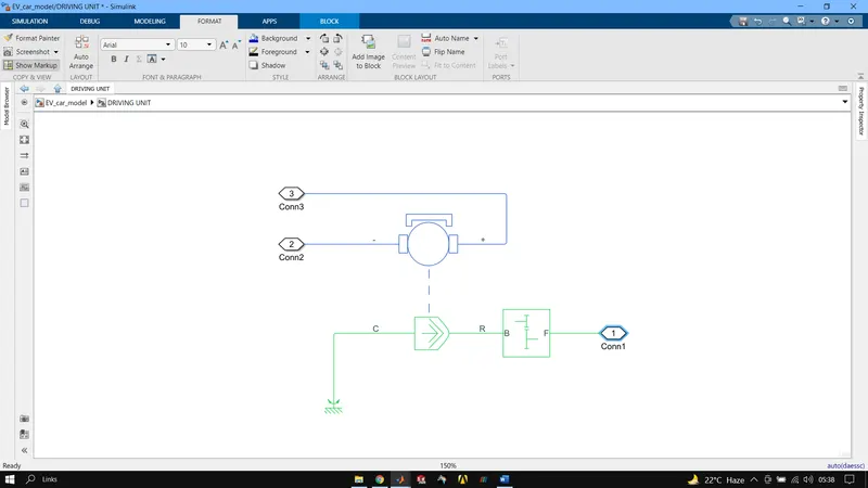
DC MOTOR BLOCK, his block represents the electrical and torque characteristics of a DC motor. The block assumes that no electromagnetic energy is lost, and hence the back-emf and torque constants have the same numerical value when in SI units.
R port represents rotor and is fed as input to vehicle velocity while C port is for stator hence is connected to a mechanical reference.
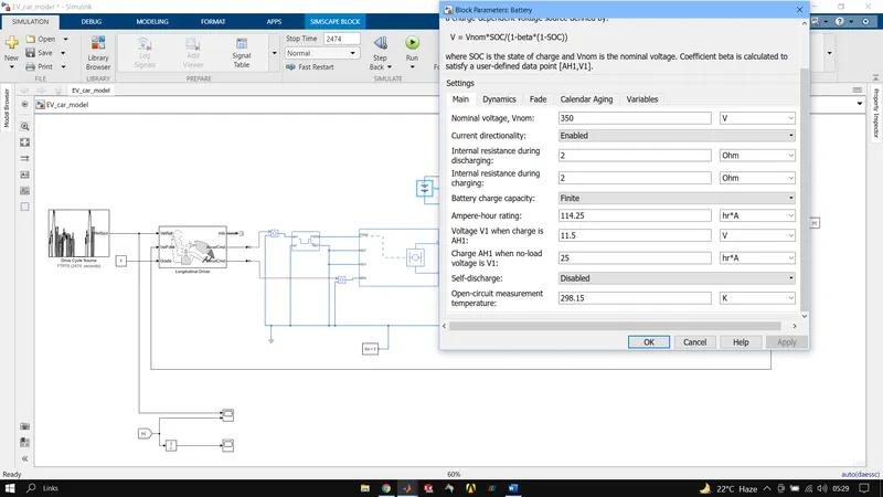
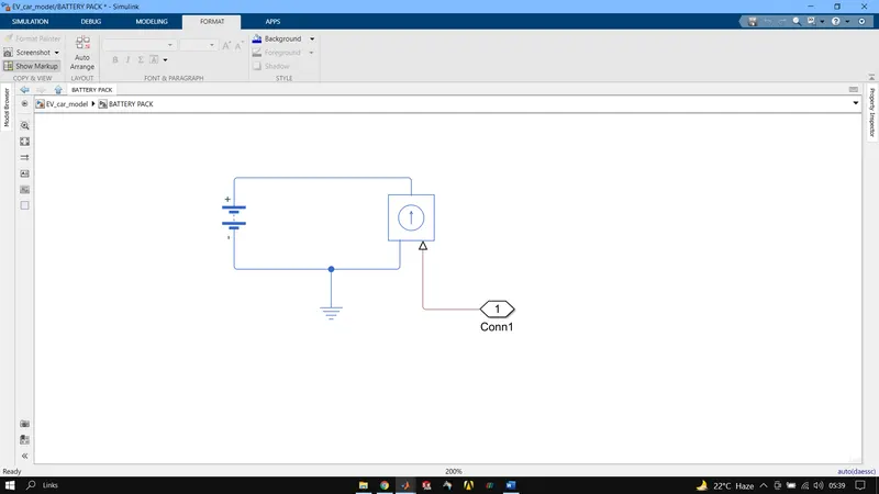
SIMPLE BATTERY BLOCK, this block models a battery. To ensure supply of current as required by motor controller and not rated values, currents sensor and controlled current source is connected along with it.
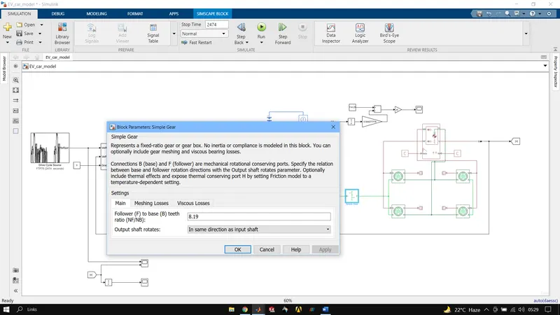
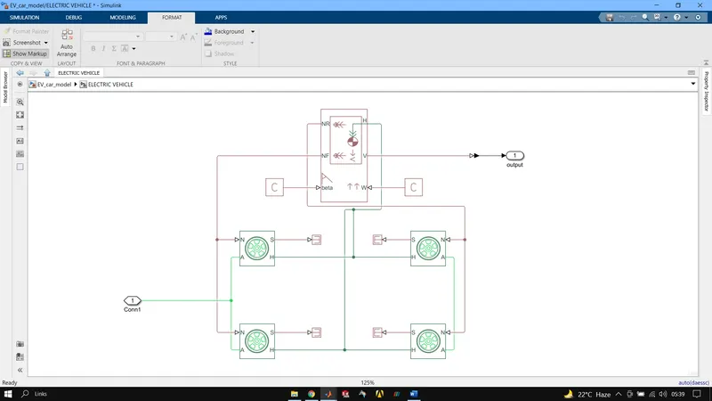
SIMPLE GEAR BLOCK, represents a fixed-ratio gear or gear box.
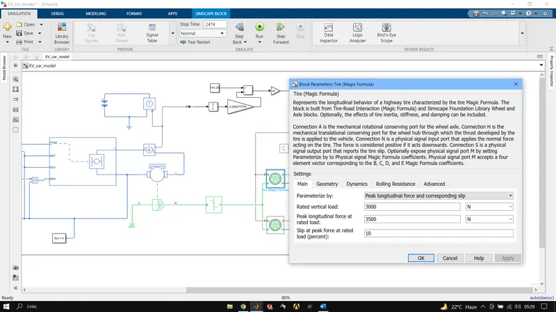
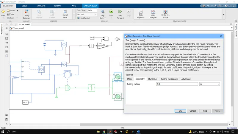
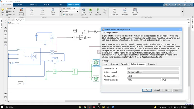
SIMPLE TIRE BLOCK, represents the longitudinal behaviour of a highway tire characterized by the tire Magic Formula. The block is built from Tire-Road Interaction (Magic Formula) and Simscape Foundation Library Wheel and Axle blocks. Optionally, the effects of tire inertia, stiffness, and damping can be included.
N represents normal reaction acting on tire, while H represents translational speed hence all 4 are connected and A represents rotational speed hence both tire on same axel are connected.
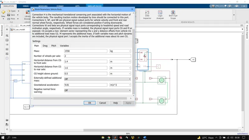
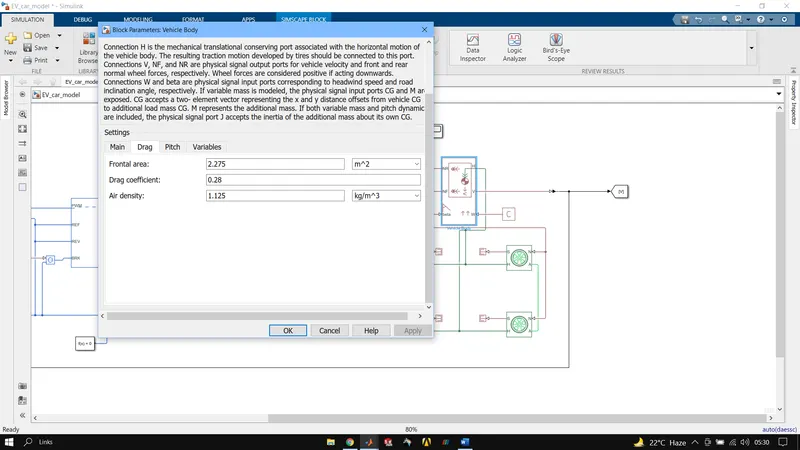
VEHICLE BODY BLOCK, represents a two-axle vehicle body in longitudinal motion. The block accounts for body mass, aerodynamic drag, road incline, and weight distribution between axles due to acceleration and road profile. The vehicle can have the same or a different number of wheels on each axle. Optionally include pitch and suspension dynamics or additional variable mass and inertia. The vehicle does not move vertically relative to the ground. NF represents the front axle neutral reaction force while NR is the same for rear axle. V is the output velocity beta is the road inclination angle and W is the headspeed.
- Results
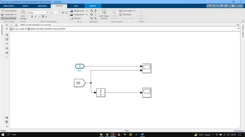
INPUT AND OUTPUT VELOCITIES
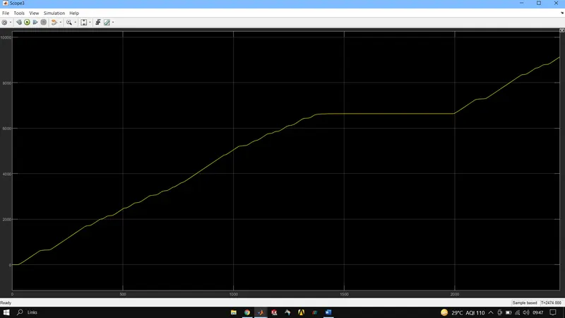
TOTAL DISTANCE TRAVELLED
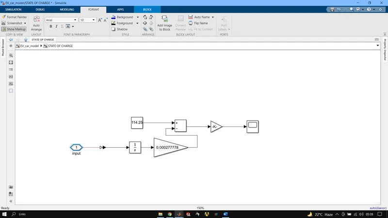
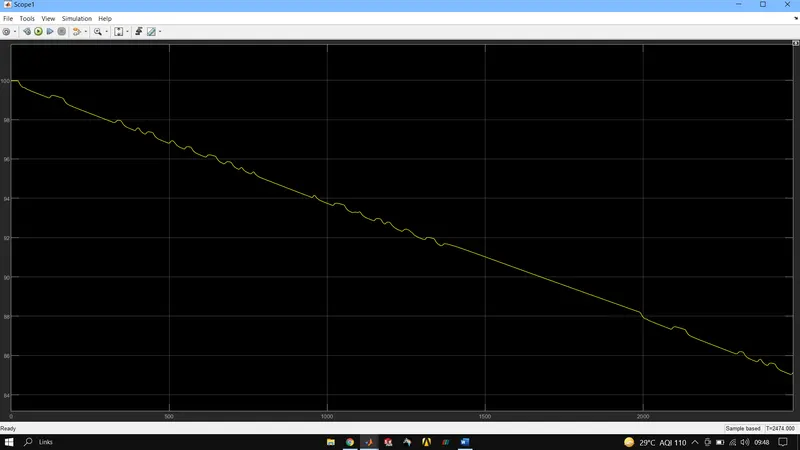
STATE OF CHARGE
- Conclusion
>We observe difference between input and output velocities as the motor and battery combination of the given values is not able to generate enough power to reach to those speeds.
>The distance covered by the vehicle is around 9000 meters.
>SOC of the vehicle after one FTP75 drive cycle is about 85%.