Project-1: Powertrain for aircraft in runways
PART(A):
SOLUTION 1: The different types of various Aircrafts weight include the following:
- Manufacturer's empty weight (MEW):
(Also called Manufacturer's Weight Empty (MWE) or Licensed Empty Weight)
It is the weight of the aircraft "as built" and includes the weight of the structure, power plant, furnishings, installations, systems and other equipment that are considered an integral part of an aircraft.This excludes any baggage, passengers, or usable fuel. -
Zero-fuel weight (ZFW):
This is the total weight of the airplane and all its contents (including unusable fuel), but excluding the total weight of the usable fuel on board.As a flight progresses and fuel is consumed, the total weight of the airplane reduces, but the ZFW remains constant.
Maximum zero fuel weight (MZFW) is the maximum weight allowed before usable fuel and other specified usable agents (engine injection fluid, and other consumable propulsion agents) are loaded.
- Operating empty weight (OEW):
(Roughly equivalent to basic empty weight on light aircraft)
It is the basic weight of an aircraft including the crew, all fluids necessary for operation such as engine oil, engine coolant, water, unusable fuel and all operator items and equipment required for flight but excluding usable fuel and the payload. - Payload:
It is the carrying capacity of an aircraft. It includes cargo, people, extra fuel. In the case of a commercial airliner, it may refer only to revenue-generating cargo or paying passengers.
-
Maximum takeoff weight (MTOW):
This is the maximum weight at which the pilot of the aircraft is allowed to attempt to take off. -
Regulated takeoff weight (RTOW):
Depending on different factors (e.g. flap setting, altitude, air temperature, length of runway), RTOW or maximum permissible takeoff weight varies for each takeoff. It can never be higher than MTOW. - Maximum landing weight (MLW):
This maximum weight at which an aircraft is permitted to land. - Maximum ramp weight (MRW):
also called maximum taxi weight (MTW)
It is the maximum weight authorized for maneuvering (taxiing or towing) an aircraft on the ground. - Aircraft gross weight:
It is the total aircraft weight at any moment during the flight or ground operation. This decreases during flight due to fuel and oil consumption.
The following image depicts takeoff weight components.
Given below is the list of various of types of Aircrafts:
MTOW = Maximum take-off weight, MLW = Maximum landing weight.
SOLUTION 2: Yes, there is a large differnce between the Air speed and thr ground speed.
- Ground Speed:
For a reference point picked on the ground, the aircraft moves relative to the reference point at the ground speed. Ground speed is also a vector quantity so a comparison of the ground speed to the wind speed must be done according to rules for vector comparisons. - Airspeed:
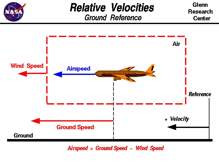
The important quantity in the generation of lift is the relative velocity between the object and the air, which is called the airspeed. Airspeed cannot be directly measured from a ground position, but must be computed from the ground speed and the wind speed.Airspeed is the vector difference between the ground speed and the wind speed.
Airspeed = Ground Speed - Wind Speed
On a perfectly still day, the airspeed is equal to the ground speed. But if the wind is blowing in the same direction that the aircraft is moving, the airspeed will be less than the ground speed and vice-versa.
The wind speed can be defined as below: - Wind Speed:
For a reference point picked on the ground, the air moves relative to the reference point at the wind speed. Wind speed is a vector quantity and has both a magnitude and a direction.
A Schematic diagram of all the three speeds is shown below:
SOLUTION 3:
The risks which may arise from engine ground running relate to the potential for loss of control of the aircraft by those persons occupying the pilot seats in the flight deck.Unwanted consequences from such static running are mainly related to those arising from the unintended movement of the aircraft during engine running - effectively a loss of control - especially during high power engine running.
Damage can occur to the aircraft itself, other aircraft nearby or to airside structures. In addition, there is a risk of injury to ground support personnel who may be in relatively close proximity to the aircraft.
When modern jet engines are operated at rated thrust levels, the exhaust wake can exceed 375 mi/h (325 kn or 603 km/h) immediately aft of the engine exhaust nozzle. This exhaust flow field extends aft in a rapidly expanding cone, with portions of the flow field contacting and extending aft along the pavement surface (fig. 1). Exhaust velocity components are attenuated with increasing distance from the engine exhaust nozzle. However, an airflow of 300 mi/h (260 kn or 483 km/h) can still be present at the empennage, and significant people and equipment hazards will persist hundreds of feet beyond this area. At full power, the exhaust wake speed can typically be 150 mi/h (130 kn or 240 km/h) at 200 ft (61 m) beyond the airplane and 50 to 100 mi/h (43 to 88 kn or 80 to 161 km/h) well beyond this point.
The figure below descibes the areas of hazard while engine ground running.
SOLUTION 4:
- In aviation, pushback is an airport procedure during which an aircraft is pushed backwards away from its parking position, usually at an airport gate by external power.
- Pushbacks are carried out by special, low-profile vehicles called pushback tractors or tugs.
- Although many aircraft are capable of moving themselves backwards on the ground using reverse thrust (a procedure referred to as a powerback, the resulting jet blast or prop wash would cause increased noise, damage to the terminal building or equipment, and hurt airport staff due to high-speed debris.
- This debris would also be sucked into the engine, as it is in normal use, and cause excessive wear - a major cause of wear on aircraft engines is during ground use.
- A pushback is therefore the preferred method when ground-handling aircraft.
- Pushbacks at busy aerodromes are usually subject to ground control clearance to facilitate ground movement on taxiways.
- Once clearance is obtained, the pilot will communicate with the tractor driver (or a ground handler walking alongside the aircraft in some cases) to start the pushback. To communicate, a headset may be connected near the nose gear.
- Since the pilots cannot see what is behind the aircraft, steering is done by the pushback tractor driver and not by the pilots
- Depending on the aircraft type and airline procedure, a bypass pin may be temporarily installed into the nose gear to disconnect it from the aircraft's normal steering mechanism.
- Once the pushback is completed, the towbar is disconnected, and any bypass pin removed. The ground handler will show the bypass pin to the pilots to make it clear that it has been removed.
- The pushback is then complete, and the aircraft can taxi forward under its own power.
SOLUTION 5:
- TAKE-OFF POWER:-
The amount of power that an engine is allowed to produce for a limited period of time for takeoff. The use of takeoff
power is usually limited to 5 min for reciprocating engines and up to 2½ min for gas turbine engines.
For light aircraft usually full power is used during takeoff. Large transport category (airliner) aircraft may use a reduced power for takeoff, where less than full power is applied in order to prolong engine life, reduce maintenance costs and reduce noise emissions.
Before takeoff, the engines, particularly piston engines, are routinely run up at high power to check for engine-related problems.
The nose is raised to a nominal 5°–15° nose up pitch attitude to increase lift from the wings and effect liftoff. For most aircraft, attempting a takeoff without a pitch-up would require cruise speeds while still on the runway. - TYRE DESIGN:-
When it comes to safety, tyres are one of the most important components of aircraft. They help to absorb the shock of landing and provide cushioning. It also provides the necessary traction for braking and stopping of an aircraft.
An aircraft tyre is designed to withstand extremely heavy loads while landing, take off, taxing, and parking. The number of wheels required for aircraft increases with the weight of the aircraft, as the weight of the aeroplane needs to be distributed more evenly.
- Design & Construction of Aircraft tyre:
Carcass plies are used to form the tire. They are sometimes called casing plies. An aircraft tyre is constructed for the purpose it serves. - They support the weight of an aircraft while it is on the ground.
- It also provides the necessary traction for braking and stopping of an aeroplane.
- Tyre also helps to absorb the shock of landing and provide cushioning the roughness of takeoff, roll-out, and taxi operations.
Unlike an automobile or truck tyre, it does not have to carry a load for a long period of continuous operation. However, an aircraft tyre absorbs the high impact loads of landing, and also it’s operating at high speeds for a short time when required.
Aircraft Tyres may be Tube-type ot Tubeless:
Tubeless tyres are more advantageous over tube-type. There is no longer the use of tube-type tyre in recent aviation. Nowadays all airliners are using tubeless tyres. Tubeless that are meant to be used without a tube has the word TUBELESS on the sidewall of the tyre.
Aircraft tyres may be Radial or Bias:
Almost all airliners are using Radial tyre. Bias is an older design, and it’s mainly used for road vehicles. Radial tyres have the word RADIAL on the sidewall. Radial tires are more expensive than bias-ply tyres. Radial tires are in demand because of their lower life cycle cost and long term value.
Aviation tyres are conductive :
Aircraft tyres are manufactured with tread rubber with conducting compounds to permit earthing of static charges. In early days when tyres were not sufficiently conductive, aircraft used to have a conductive strip hanging down from the axle of the landing gear. Upon landing, this strip would be the first part of the aircraft to touch the earth. This discharges any static electricity accumulated on the outer surfaces of the aircraft. Now you don’t see them anymore.
Purpose of Chines in Aviation tyre:
Chines are also called deflectors. Chine tyre used on the nose wheel of aircraft, specially fuselage-mounted jet engines. It diverts runway water away from the engine inlets.
Chines are circumferential protrusions that are moulded into the sidewall of nose tyres that deflect water sideways to help reduce excess water ingestion into the engines. Tyres may have chines on one or both sides, depending on the number of nose tyres on the aircraft.Chines are circumferential protrusions that are moulded into the sidewall of nose tyres that deflect water sideways to help reduce excess water ingestion into the engines. Tyres may have chines on one or both sides, depending on the number of nose tyres on the aircraft.
AIRCRAFT TYRE STANDARDS :
Each tyre manufacturer produces their own designs of the tyre with different tread patterns, wear patterns, wear limits etc, and in some cases, different names for the same part of the tyre. But all tyres must meet the approved standards before being accepted by the FAA or CAA.
All commercial aircraft tyres approved under FAA Requirement Technical Standard Order (TSO) C62. A TSO is a minimum performance standard for specified materials, parts, and appliances used on civil aircraft.
iii. ROLLING RESISTANCE:
Rolling resistance, sometimes called rolling friction or rolling drag, is the force resisting the motion when a body (such as a ball, tire or wheel) rolls on a surface.
It is mainly caused by non-elastic effects; that is, not all the energy needed for deformation (or movement) of the wheel, roadbed, etc., is recovered when the pressure is removed.
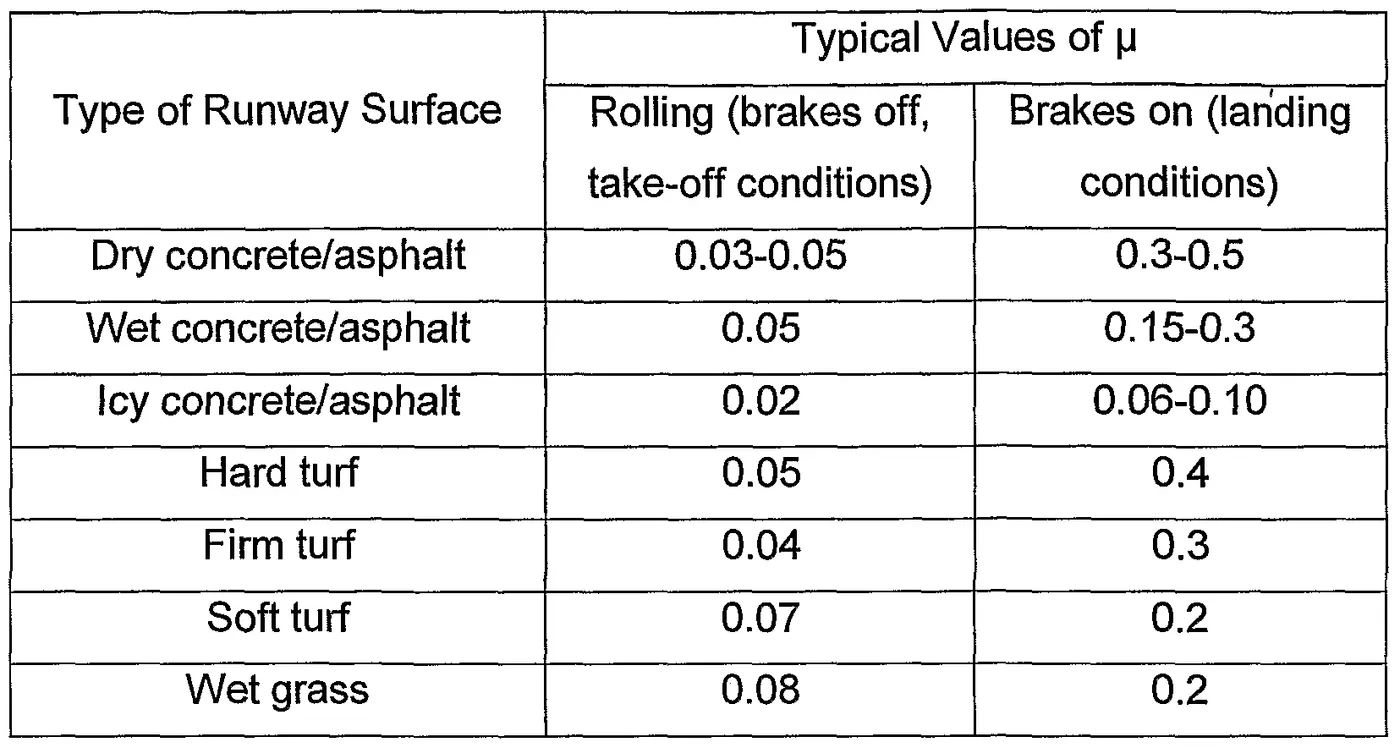
Analogous with sliding friction, rolling resistance is often expressed as a coefficient times the normal force. This coefficient of rolling resistance is generally much smaller than the coefficient of sliding friction.
Some typical values of Rolling resistance coefficient under different ruway surfaces is shown below:
iv.) TYRE PRESSURE :
Aircraft tires generally operate at high pressures, up to 200 psi (14 bar; 1,400 kPa) for airliners, and even higher for business jets. Tests of airliner aircraft tires have shown that they are able to sustain pressures of maximum 800 psi (55 bar; 5,500 kPa) before bursting. During the tests the tires have to be filled with water, to prevent the test room being blown apart by the energy that would be released by a gas when the tire bursts.
Aircraft tires are usually inflated with nitrogen to minimize expansion and contraction from extreme changes in ambient temperature and pressure experienced during flight.Dry nitrogen expands at the same rate as other dry atmospheric gases (normal air is about 80% nitrogen), but common compressed air sources may contain moisture, which increases the expansion rate with temperature.
v.) Brake Forces while landing :
All modern aircraft are fitted with a braking system to assist in slowing and stopping when on the ground. Brakes are used not only to decelerate during a landing run, but also to hold the aircraft during an engine run-up, and in some cases to steer the aircraft through differential braking. Brakes are fitted to the main landing gear but not generally to the nose or tail wheel.
Brakes work by dissipating energy as heat through the action of friction. An aircraft wheel rotating at speed possesses a large amount of kinetic energy. By contacting the wheel with a semi-metallic or ceramic brake pad, an enormous amount of heat is generated as a result of the friction between the two contacting surfaces.
Traditionally, brakes are fitted to the upper half of the rudder pedals and are actuated through the pilot applying pressure to the top of each pedal. This toe-brake configuration is widely used and allows the pilot to apply differential braking by varying the pressure applied on each toe brake.
Many smaller light sport aircraft do not make use of toe brakes, preferring to use a simpler single lever mechanism. This lever is usually situated in the cockpit centre console and applies equal braking to all main wheels when engaged.
The advantages of a single braking system include reduced complexity and lower part count when compared to toe-brakes. However, differential braking is clearly not possible with a single lever mechanism.
Most aircraft are fitted with a parking brake which can be applied through a switch or lever and will keep all brakes engaged when applied.4
PART (B)
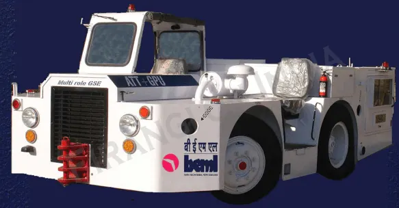
SOLUTION 6 (A): In this study, we need to calculate the Force and power required to Push and Pull an aircraft by a towing vehicle. So, we take one of the towing vehicle model and an Airbus model data from the website for our study.
AIRCRAFT TOWING TRACTOR – MODEL BA10G40
| To Push or Pull | Up to75 Tons (Take-off weight, up to 2% gradient) | ||
| Boeing | B737 – 100 to 900 series Aircrafts | ||
| Air Bus | A319, A320 & A321 Aircrafts | ||
| To Start & Service | Up to 40 kVA (ground power requirement with AC/DC & 400 HZ | ||
| – Triner/Military (Kiran, MiG, Jaguar, Mirraj & Sukhoi) | |||
| – Commercial Aero-planes with 12 to 16 seater | |||
| – Helicopters | ALH & Mi 17 | ||
Gross weight=10,100 Kg
| Length (Over all) | 4905 mm = 4.905m | ||
| Width (Over all) | 2375 mm = 2.375m | ||
| Height (Over all) | 1350 mm = 1.35m | ||
| Frontal Area(width*height) | 3.206m^2 |
Tyre size=R 20 =508mm =.508m
Maximum vehicle speed= 25Kmph= 25*(5/18) m/s
=6.944m/s
The coefficient of friction depends on the objects that are causing friction. Its value can range from 0 to 1 and also greater than 1. A 0 value means that there is no friction at all. The value of 1 means that the friction force is equal to the normal force.
Coefficient of rolling resistance (`murr`)= 0.03 (runway surface made of dry concrete /asphalt)
AIRCRAFT MODEL :
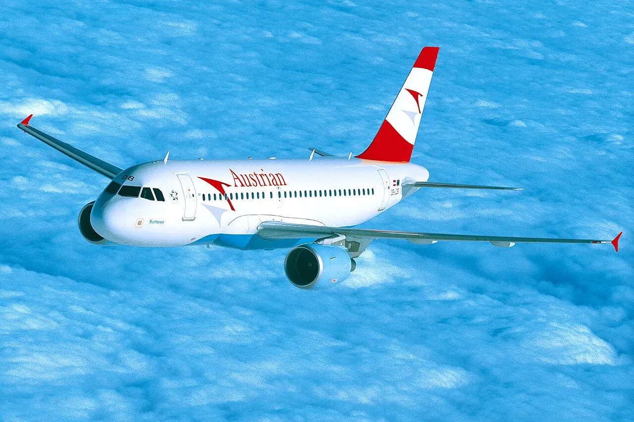
We are takig an aircraft model of AIRBUS A319 as pushback operation. The advanced technologies and specifications of AIRBUS A319 are given below.
The Airbus A319 is a member of the Airbus A320 family of short- to medium-range, narrow-body, commercial passenger twin-engine jet airliners manufactured by Airbus.The A319 carries 124 to 156 passengers and has a maximum range of 3,700 nmi (6,900 km; 4,300 mi). Final assembly of the aircraft takes place in Hamburg, Germany and Tianjain,China.
Gross weight=40,823.3Kg
Wingspan Area=122.4m^2
Drag coefficient (Cd)=0.05
TO FIND :
To find the force and power required to push/pull an aircraft by a towing vehicle.
Formula used :
Total Force, Fte=Frr + Fad
Rolling resistance force, Frr=`murr`*m*g
Drag force, Fad=0.5*rho*A*v^2 {A=wingspan area+Frontal area(ATV)}
In the first step, we want to find rolling resistance force and drag force for both Towing vehicle and Airbus to find the foce and power during the Towing process.
To find rolling resistance force :
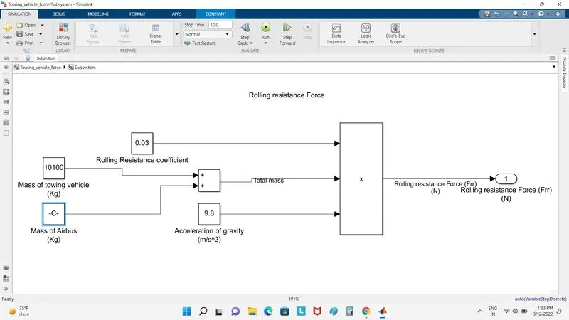
Rolling resistance force, Frr=`murr*m*g`
Here, (m) is the total mass of towing vehicle and airbus, so
(m)=(48823.3+10100)Kg
`implies` m= 58923.3 Kg`
substituting mass(m) value in rolling resistance formula:
Frr = (0.03*58923.3*9.8)N
Frr= 17,323.45 N
To find the air drag force :
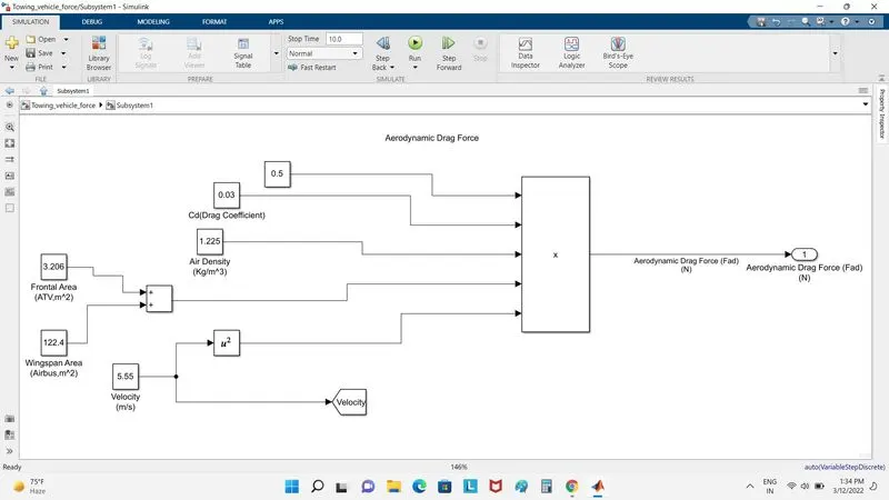
Drag force, Fad=0.5*rho*Cd*A*v^2
According to the International Standard Association (ISA) values, air density=1.225Kg/m^3
`rho`= 1.225Kg/m^3
Frontal Area = width of Airbus*height of Airbus
A = (122.4+3.206) = 125.6m^2
substituting the values of rho and A in the formula of drag force formula when the speed is 20Kmph=20*(5/18)=5.55m/s.
Fad = 0.5*1.225*0.03*125.6*(5.55)^2
Fad = 71.09 N
Hence, Total force Fte=Fad+Frr
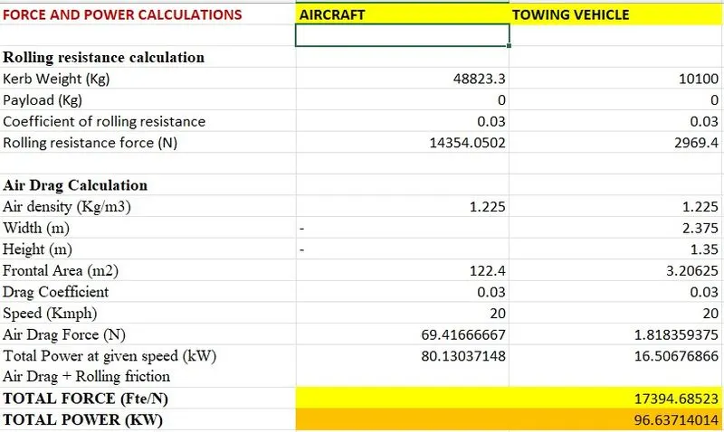
`impliesFte=17323.45+71.09=17394.54 N`
Fte = 17394.54 N= 17.394 KN
To find the Power required by Towing vehicle :
The Towing power is calculated by multipying the Total force and velocity:
Ptow =Fte*v
Ptow = 17394.54*5.55= 96.539KW
To find the Torque of the vehicle:
Torque(T) = Fte*R = 17394.54*0.508= 8836.42 Nm
SOLUTION 6(B) : The simulink model for the calculation of above Force and Power is shown in the images below.
In the model, there are 2 subsystems namely:- Rolling resistance force & Aerodynamic drag force.
- ROLLING RESISTANCE SUBSYSTEM.
- AERODYNAMIC DRAG FORCE.
- FINAL SIMULINK MODEL (MAIN SYSTEM).
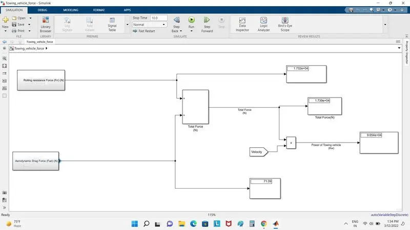
- The value of rolling resistance force is 17.32KN, Aerodynamic drag force is 71.09N and the overall force is 17.09KN; the Power of Towing vehicle is 96.54Kw.
SOLUTION 7(A):
From the previous question, it can be seen that the minimum amount of power rating of the motor required is 96.54 Kw.
Since Torque is also an important feature so we need to calculated the amount of Torque required before choosing the motor.
`T=(F*r)/(G*etag)`
Assuming the Gear ratio of ATV MODEL BA10G40 to be genrally high to around 27, the wheel radius r=0.508m as is given in the data.
`therefore` T=(17320*0.508)/(27*0.95) {assuming gear efficiency be 95%`
we have, T= 343.02 Nm
Now, `omega=(Pout)/(Tout)`=(96540/343.02)`
`omega= 281.43 (rad)/(s)`
`o speed in RPM(N)=(281.43*30)/3.14=2687.53
As per the above specifications, we can choose the following ABB IE3 MOTOR
SPECIFICATIONS:
DATA SHEET
| COUNTRY OF ORIGIN | INDIA |
| MOTOR HP | 150 |
| MOTOR KW | 110 |
| MOTOR POLE | 2 POLE |
| MOTOR RPM | 3000 RPM |
| MOTOR MOUNTING TYPE | FOOT MOUNTED |
| MOTOR INSULATION TYPE | CLASS F |
| RATED VOLTAGE | 415V (+/-10%) |
The motor needs to generate an output power of 96.54Kw.Assuming the motor effciency to be 90%,we can calculate the input power by the relation:
`eta=(Pout)/(P i)`
`impliesP i=(Pout)/eta`=(96539)/0.9`
Pi=107265W-------------------------------------------------------This much power is to be supplied by the battery.
Electric Power train:
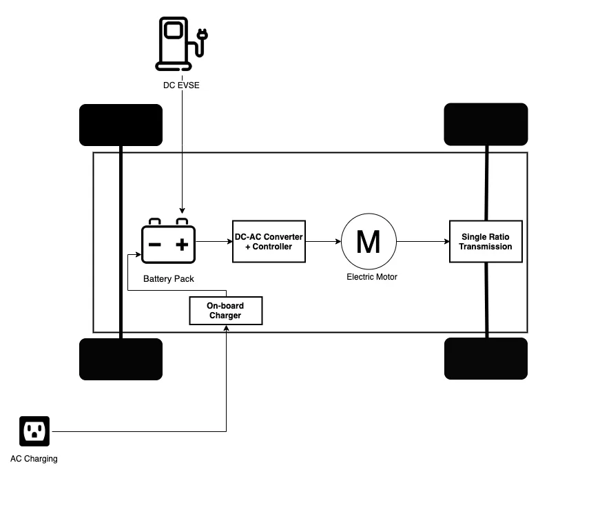
Above is a basic block diagram of Electric power train. The motor parameters have been determined and now it must receive power from the battery through a power controller. The power controller is assumed to be 100% efficient.
BATTERY :
Everything calculated above is based on the assumption that the vehicle moves with a maximum speed of 5.55m/s. The battery must supply full load current to meet this speed.
Full load current (Ii) : `((P i)/(sqrt3*Vmr*PF))`
where; Vmr=415V (as per motor specifications)
PF= power factor of the motor generally between the range 0.85 to 0.9 for full load.
`Ii=((107265)/(sqrt3*415*0.88))`
`Ii=169.57 A.................................................................................current drawn by the motor when operating at full load`
Now, the voltage of the battery (Vbat) can be calculated as:
Vbat=(Pi/Ii)
Vbat=(107265/169.57)=632.54V
Vo=Vbat*d........{Vo=voltage output of the power converter/voltage obtained at the motor input terminals}
Now since , the motor rating is 415 V, so the input voltage cannot exceed this value otherwise it will damage the motor.
here, d= Duty cycle of the power converter. Thus:
d=(Vo/Vbat) = (415/632.54) = 0.656................So, the duty cycle ranges from 0 to 0.656 to contol speed of ATV from zero to highest.
ENERGY REQUIREMENTS :
Assuming the battery takes 60sec to completely discharge its energy to the power converterr and hence to the motor.
The energy can be calculated by the relation:
E=Pi*t = 107265*60 = 6435900 J
Converting this energy into KWH
E=(6435900/(1000*3600))= 1.787 KWH.........this is the minimal rating of the battery.
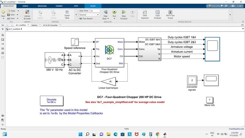
- DC7 BLOCK DIAGRAM :
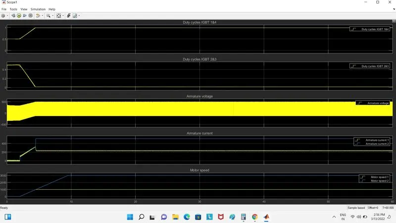
- OUTPUT RESULTS :
SOLUTION 7(B) :
The Total Force and Power required to push/pull the aircraft AIRRBUS A319 fromm the towing vehicle MODEL BA10G40 has also been done in the excel calculator with the necessary assumptions. The Excel file has aalso been attached at the end.