Project-1: Powertrain for aircraft in runways
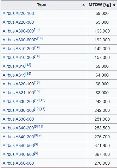
Search and list out the total weight of various types of aircrafts.
Is there any difference between ground speed and air speed?
Ground Speed
For a reference point picked on the ground, the aircraft moves relative to the reference point at the ground speed. Ground speed is also a vector quantity so a comparison of the ground speed to the wind speed must be done according to rules for vector comparisons.
Wind Speed
For a reference point picked on the ground, the air moves relative to the reference point at the wind speed. Notice that the wind speed is a vector quantity and has both a magnitude and a direction. Direction is important. A 20-mph wind from the west is different from a 20-mph wind from the east. The wind has components in all three primary directions (north-south, east-west, and up-down). In this figure, we are considering only velocities along the aircraft's flight path. A positive velocity is defined to be in the direction of the aircraft's motion. We are neglecting cross winds, which occur perpendicular to the flight path but parallel to the ground, and updrafts and downdrafts, which occur perpendicular to the ground.
Airspeed
The important quantity in the generation of lift is the relative velocity between the object and the air, which is called the airspeed. Airspeed cannot be directly measured from a ground position, but must be computed from the ground speed and the wind speed. Airspeed is the vector difference between the ground speed and the wind speed.
Airspeed = Ground Speed - Wind Speed.
Why is it not recommended to use aircraft engine power to move it on the ground at Airport?
Boeing commercial airplanes are equipped with engines rated from 18,000 to nearly 100,000 lb of thrust. Such thrust levels provide for safe take off, flight, and landing over a wide range of temperatures, altitudes, gross weights, and payload conditions. However, the exhaust wake from these engines can pose hazards in commercial airport environments. Operators and airport authorities must carefully consider these hazards and the resulting potential for injury to people and damage to or caused by baggage carts, service vehicles, airport infrastructure, and other airplanes.
How an aircraft is pushed to runway when its ready to take off?
Pushback is when an aircraft is pushed backwards away from the airport gate by vehicles called Tow truck or tractors. Closer to departure, an aircraft tow truck will park right in front of the nose wheel. The tow truck might be directly attached to the plane's nose gear with a tow bar, or could be a "wheel-lift" truck. These tow truck cradle the nose gear, then lift it up before moving the plane. That gives the tow truck driver control over the plane's direction during pushback. New taxi technologies are appearing, like pilot-controlled Tow truck, and electric motors mounted to the plane's landing gear. Both promise to save fuel, and reduce airport noise.
Q 6 A) To calculate the force and power required to push / pull an aircraft by a towing vehicle.
- The forces acting on the airplane & towing vehicle Analysed
The forces mainly associated with the moving of airplane with help of tow vehicle are Rolling Resistance force and Aerodynamic Drag force.
1) Rolling Resistance Force:
This force is experience by the tyre of vehicle when it's moving on any surface.
The rolling resitance force is given as,
Frr = Urr * (m.g)
Where, m.g is the weight of vehicle.
Urr is the rolling resistance coefficient
The rolling resistance coefficient is depends upon factors like, Tyre Pressure, Temperature, Material of Tyre, Thread Pattern, road Roughness and manny more.
We Calculate Rolling resistance force for tow vehicle and Airplane and then add them togather.
Calculations:
i) For Tow Truck-
Mass of Tow Vehicle = 50,000 kg
Inertia of 5% = 2500 kg
Coefficient of Rolling Resistance for Tow Truck = 0.0035
Therefore, For Tow Truck Frr is,
Frr1 = 0.0035 x (50000+2500) x 9.81
Frr1 = 1802.59 N
Frr1 = 1.80 kN
ii) For Airplane-
Mass of Airplane = 371950 kg
Inertia of 5% = 18597.5 kg
Coefficient of Rolling Resistance for Airplane = 0.004
For Airplane Frr is,
Frr2 = 0.004 x (371950+18597.5) x 9.81
Frr2 = 15325.08 N
Frr2 = 15.33 kN
The Total Rolling Resistance Force is given by = Frr1 + Frr2 = 1.80 + 15.33 = 17.13 kN
2) Aerodynamic Drag Force:
The Aerodynamic Drag force is that force which occures due to the Air striking effect on the vehicle when it moves. The Vehicle moves through a Air medium of perticular density value with certain speed, this causes the air to strike against the vehicle body and it causes a drag force on the vehicle.
The Aerodynamic Drag force is given by,
Fad = 0.5 * Air Density * Frontal Area * Drag Coefficient * Velocity^2
Calculations:
i) For Tow Truck-
Velocity of Tow Truck = 15 km/hr = 15 x 5/18 = 4.167 m/sec
Air Density = 1.25 kg/m^3
Aerodynamic Drag Coefficient for tow truck (Cd) = 1.15
Frontal Area of Tow truck = 1.9 m^2
Therefore, Aerodynamic Drag Force is given by,
For Tow Truck,
Fad1 = 0.5 * Air Density * Frontal Area * Drag Coefficient * Velocity^2
Fad1 = 0.5 * 1.25 * 1.9 * 1.15 * 4.167^2 = 23.71 N
ii) For Airplane,
Aerodynamic Drag Coefficient for Airplane (Cd) = 0.025
Frontal Area of Airplane = 25 m^2
Fad2 = 0.5 * air density * Frontal Area * Drag Coefficient * Velocity^2
Fad2 = 0.5 * 1.25 * 25 * 0.025 * 4.167^2 = 6.782 N
Therefore, Total Aerodynamic Drag Force is given by,
Fad1 + Fad2 = 23.71 + 6.782 = 30.49 N = 0.030 kN.
Total Tractive Force is given by, Sum of Rolling Resitance force and Aerodynamic Drag force
Ft = Frr + Fad
Ft = 17.13 + 0.030
Ft = 17.16 kN
- Power Required by Motor:
The power required by the motor is given by the velocity with which the towing operation takes place.
The average speed of the Push/Pull of airplane is,
V = 15 km/hr = 4.167 m/sec
Power = Tractive Force * Velocity
Power = 17.16 * 4.167
Power = 71.49 kW
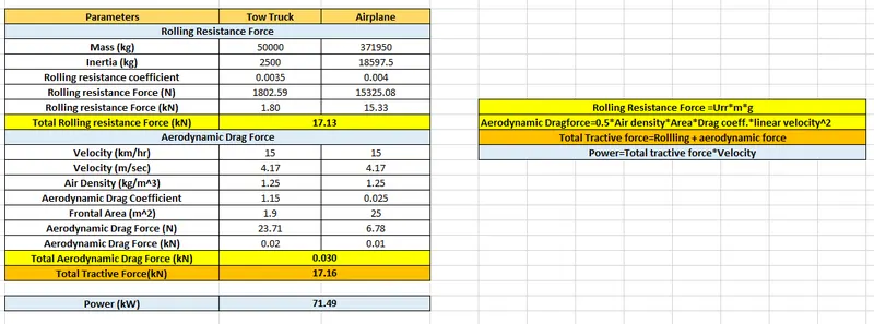
Excel Calculator:
Q 6 B) Develop the model for the calculated force and power using Simulink.
Simulink model for Power calculation is given below,
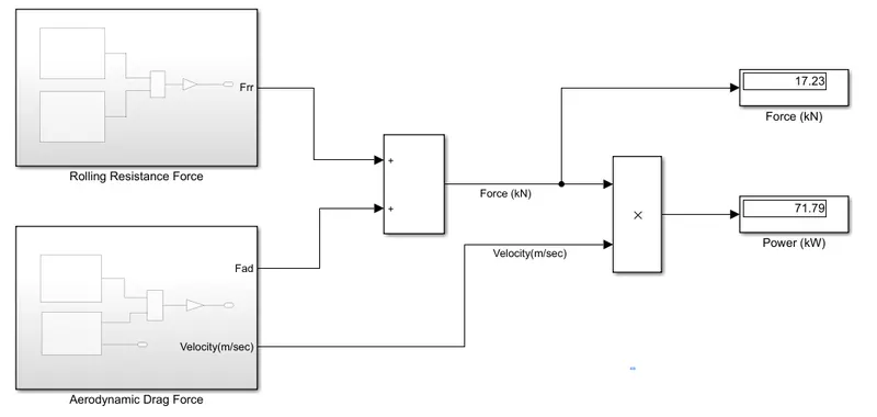
Inside Subsytem 1 i.e. Rolling Resistance force, model for Frr1 & Frr2
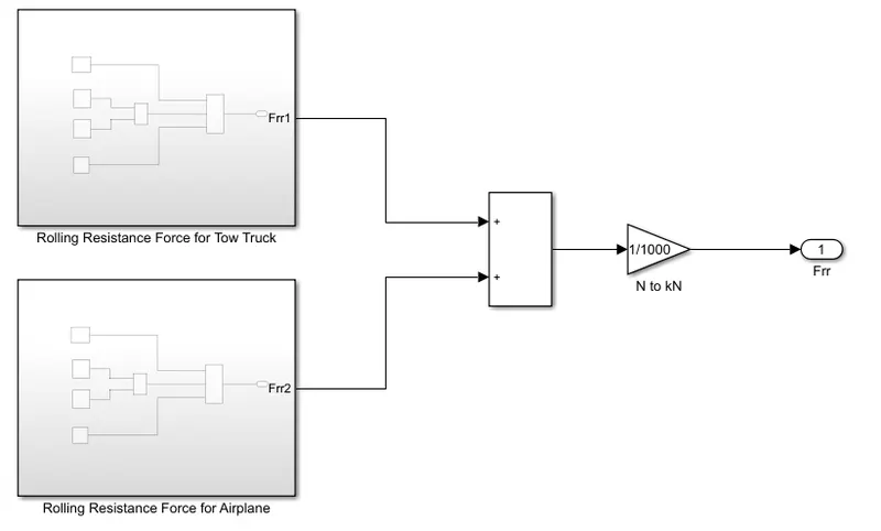
Subsystem 2- Calculation of Frr = Urr * m * g.

Inside Subsytem 3 i.e. Aerodynamic Drag force, model for Fad1 & Fad2
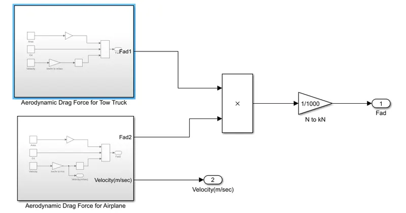
Subsystem 4- Calculation of Fad = 0.5 * frontal area * air density * velocity^2
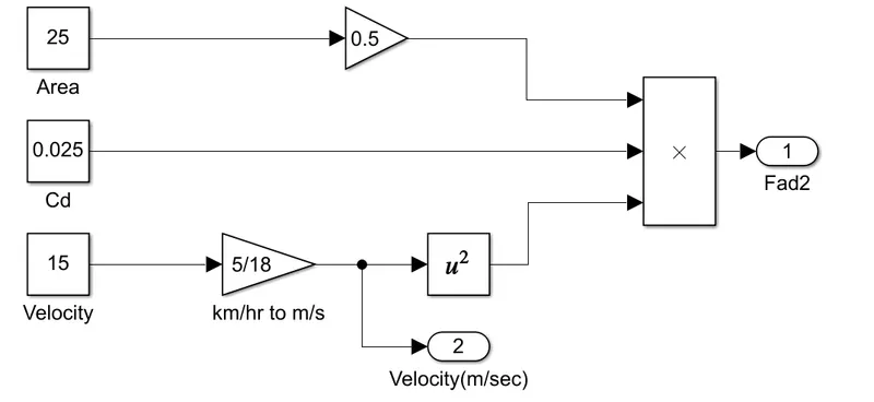
According to calculations in Simulink Power = 71.79 kW & Force = 17.23 kN
Q 7 A) Design an electric powertrain with type of motor, it’s power rating, and energy requirement to fulfill aircraft towing application in Simulink.
What is Powertrain?
As the name suggests, the Powertrain provides power to the vehicle. Powertrain refers to the set of components that generates the power required to move the vehicle and deliver it to the wheels.
Assumption for Powertrain Design-
1) Mass of Tow Truck = 50000 kg
2) Mass of Airplane = 371950 kg
3) Inertia = 5% of Mass
4) Air Density = 1.25 kg/m^3
5) Velocity = 4.167 m/sec
6) Frontal Area of tow truck = 1.9 m^2
7) Frontal area of Airplane = 25 m^2
8) Coefficient of Rolling Resistance of tow truck = 0.0035
9) Coefficient of Rolling Resistance of Airplane = 0.004
10) Coefficient of Aerodynamic Drag of tow truck = 1.15
11) Coefficient of Aerodynamic Drag of Airplane = 0.025
12) Radius of wheel of Tow Truck = 0.50 m
13) Operating Time of vehicle = 15 min = 15*60 = 900 sec = 0.25 hr
14) Tractive Force = 17.16 kN (from Excel Calculator)
15) Power Required to tug Airplane = 71.49 kW (from Excel Calculator)
16) Gear Ratio = 11
17) Torque is given by,
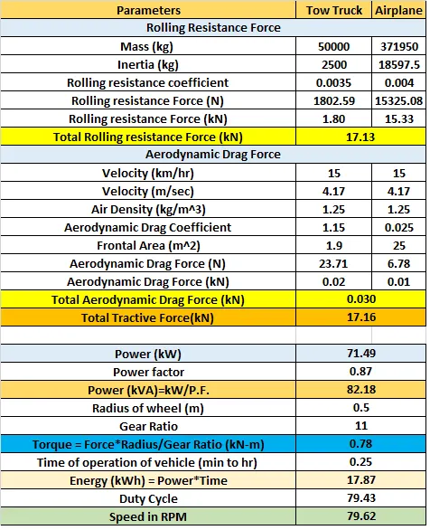
Torque = Force * Radius of wheel/Gear Ratio
Where, Gear Ratio for delivering high Power = 11
Torque = 17.16 * 0.5/11
Torque = 0.78 kN-m
18) Energy required to towing application is,
Energy = Power * Time
Energy = 71.49 * 0.25
Energy = 17.87 kWh.
Therefore, The battery must be able to store the energy of 17.87 kWh and should deliver the energy throughout the run time in order to produce the 0.78kN-m of torque instantaneously. Thus the storage of energy in batteries with high performance lithium ion batteries.
Motor Selection:
For Towing operation, we can use following types of machines
- 3 phase induction Motor
- BLDC Motor
- Permanent Magnet Synchronous Motor
- Switched Reluctance Motor
From this we choose here 3 phase Induction Motor of standard rating of 90 kW.
If we check that available Induction motor of the rating is 90 kw, 120 HP
Nameplate Specifications
|
Output HP: |
120 Hp |
Output KW: |
90.0 kW |
|
Frequency: |
50 Hz |
Voltage: |
400 V |
|
Current: |
158.5 A |
Speed: |
1485 rpm |
|
Service Factor: |
1 |
Phase: |
3 |
|
Efficiency: |
94.2 % |
Power Factor: |
0.87 |
|
Duty: |
S1 |
Insulation Class: |
F |
|
Frame: |
280M |
Enclosure: |
Totally Enclosed Fan Cooled |
|
Ambient Temperature: |
40 °C |
Drive End Bearing Size: |
6317 |
Technical Specifications
|
Electrical Type: |
Squirrel Cage |
Starting Method: |
Direct On Line |
|
Poles: |
4 |
Rotation: |
Bi-Directional |
|
Mounting: |
B3 |
Motor Orientation: |
Horizontal |
|
Drive End Bearing: |
C3 |
Opp Drive End Bearing: |
C3 |
|
Frame Material: |
Cast Iron |
Shaft Type: |
Keyed |
|
Overall Length: |
1061 mm |
Frame Length: |
550 mm |
|
Shaft Diameter: |
75 mm |
Shaft Extension: |
140 mm |
|
Assembly/Box Mounting: |
R Side |
Efficiency = Output/Input
Input = Output/Efficiency
Input = 71.49/94.2 = 75.89 kW
Input side Mechanical Power for Induction motor = 75.89 kW
The Motor output power is the input power of the towing vehicle so to obtain maximum speed, the duty cycle needed is calculated as below,
Duty Cycle = Output Power/Input Power
Duty Cycle = 71.49/90 = 0.7943 = 79.43%
So, the duty cycle will be 79.43%
The Duty Cycle range to control the airplane speed from zero to highest is from 0 to 79.43%
Block Diagram of Powertrain:
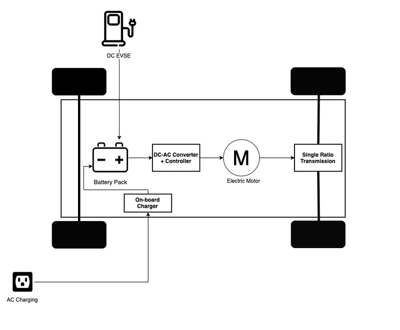
Components in the Powertrain are:
1. On Board charger- used when direct AC supply is use to charge battery, it have AC to DC converters.
2. Battery Pack- Battery pack have no. of small lithium ion batteries in series and parallel combination. It provides DC output. As per Motor supply we have to use converters.
3. DC - AC converter- DC supply of batter convert into AC for electric motor.
4. Motor- Electric Motor might be DC or AC, which converts electric energy into mechanical energy.
Simulink Model :
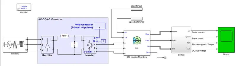
In above Simulink model, there is 3 phase power source which provides supply to battery on DC-AC converter and this again covert using Inverter for electric motor.
For Simulation we use DTC induction motor drive and change the value in the model as per our motor requirements.
Three phase supply- 400V, 60 Hz
Motor Ratings- Power = 71.49 kW = 82.17 kVA (kW = kVA * power factor)
Voltage = 400 V, 60 Hz
Speed (RPM) = 60*velocity(m/sec) / [2pi*radius]
= 60 * 4.197 / [2*3.14*0.5]
= 79.62 = 80 RPM
From the grid or Power supply, AC power is converted into DC for Lithium-Ion batteries and then again converted into AC because we use AC induction motor in Tow truck.
For Conversion process in Converter 6 Pulse bridge rectifier is used. The filtered Dc voltage is applied to an IGBT two level inverter which generates 60 Hz. The IGBT inverter uses PWM technique at 2kHz carrier frequency.
This Motor has 3 phase winding at the stator and a wound rotor. The Squirrel cage or wound rotor consist of slots of conducting bars embedded in the rotor iron. The conducting bars shorted together at each end of the rotor by conducting rings.
The induction motor is fed from PWM VSI which is built using a universal bridge block. The DTC block computes motor torque and flux estimate and compares them respective reference. The comparator output is then used by an optimal switching table which generates the inverter switching pulse.
Motor Current, speed & torque signals are available at the output of the block.
Simulation Results:
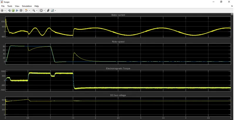
At 0 sec, the speed = 80 RPM
Torque at 0sec = 0, 0.5sec = 780Nm, 1.5sec = -780Nm
B) Design the parameters in excel sheet.