Powertrain for aircraft in runways
AIM:
6. A. With necessary assumptions, calculate the force and power required to push / pull an aircraft by a towing vehicle.
B. Develop the model for the calculated force and power using Simulink.
7. A. Design an electric powertrain with type of motor, it's power rating, and energy requirement to fulfill aircraft towing application in Simulink. Estimate the duty cycle range to control the aircraft speed from zero to highest. Make all required assumptions. Prepare a table of assumed parameters. Draw a block diagram of powertrain.
(Hint :DC7 Block)
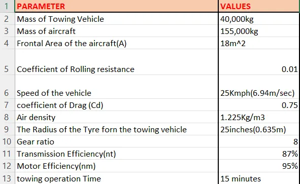
8. Also, Design the parameters in excel sheet.
Introduction:
6. A. calculating the force and power required to push / pull an aircraft by a towing vehicle:
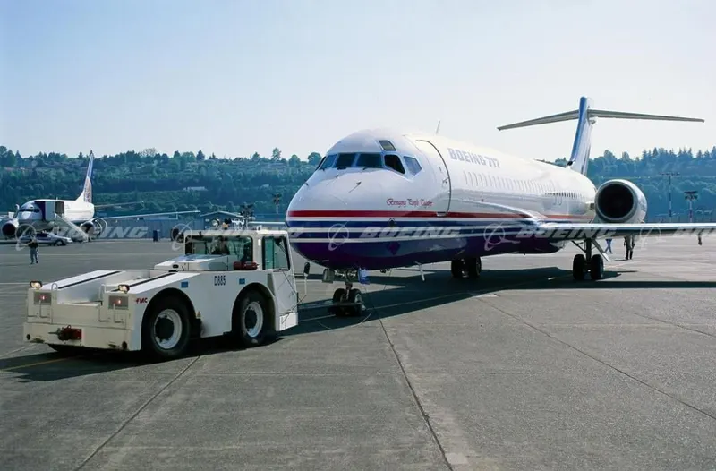
The forces required to push/ pull an aircraft by a towing are rolling resistance force and areodynamic drag force. 1) Rolling resistance force:- As we have discussed in part-A 5c. It is the force resisting the motion when a body (such as a ball, tire, or wheel) rolls on a surface. Its governing equation is given as
F = CN
F=C*m*g
where,
Crr= Rolling resistance coefficient m=Mass of the body g= acceleration due to gravity
2)Aerodynamic Drag Force:
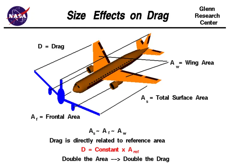
It is the force opposing the motion of the body. The drag coefficient is a common measure in automotive design as it pertains to aerodynamics, Drag is a force that acts parallel to and in the same direction as the airflow. The drag coefficient of an automobile measures the way the automobile passes through the surrounding air. When automobile companies design a new vehicle, they take into consideration the automobile drag coefficient in addition to the other performance characteristics. Aerodynamic drag increases with the square of speed; therefore, it becomes critically important at higher speeds. Reducing the drag coefficient in an automobile improves the performance of the vehicle as it pertains to speed and fuel efficiency. The governing equation of these force is given as following:
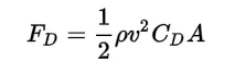
where.
F{D} = dra force
rho = r density of the air
น = flow velocity relative to the object
C{D} = drag coefficient
A = reference area
Calculation:
let us assume that,
Mass of Towing Vehicle= 40,000kg
Mass of aircraft = 155,000kg
Total mass (m)= 40,000+155,000 =195,000kg
Frontal Area of the aircraft (A) =18 m²
Speed of the vehicle (2)=25Kmph
converting it into m/sec
u=25*(1000/3600)=6.9445m/sec
Drag coefficient (Cd) =0.75
Air density (P)=1.225Kg/m³
Calculating Rolling resistance Force (Frr) =Crr*m*g
=0.01*195.000*9.8
= 19.11ON
Calculating Aerodynamic Drag Force (Fd)=0.5*p Cd*A* v^2
=0.5 *1.225 *18* 0.75* (6.9445)2
=398.769N
Therefore the total Force required to push/pull the aircrcraft by the towing vehicle (F) Frr+Fd
=19,110+398.769
=19,508.769 N
Calculating the power (p) =Force*Velocity
= 19508.769* 6.9445
=135.478kW
B. Developing the model for the calculated force and power using Simulink:
Blocks Used:
1) Constant
2) Sum
3) Product
4)Square
5)Display
Link:- https://drive.google.com/file/d/1y9HWI5uCSQNqT9okv930sXOXnCyRQjin/view?usp=sharing
Simulink Model:
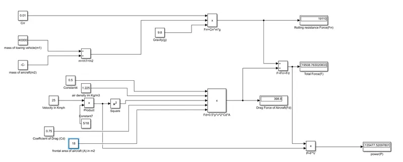
Explaination:
In order to understand the above simulink model we do reverse engineering
• For calculating power we have to multiply both total force(F) and velocity in m/sec for this we have used 'product' block (P-FV).
• For calculating the Total Force(F) we have added both Frr & Fd by using 'Surn' block as shown in the above figure
• To find the value of rolling resistance (Frr) we used product to multiply the values Crr., Total mass(m) & gravity (g) which are to be entered in the 'Constant block.
. Similarly for calculating Drag force(Fd) we have to multiply the velocity in m/sec.Drag coefficient, Frontal area of aircraft(A) and a constant value 0.5 which are to be entered in constant block.
• In order to convert velocity in Kmph to m/sec we have multiplied it with 5/18.
7) A. Designing an electric powertrain with type of motor, it's power rating, and energy requirement to fulfill aircraft towing application in Simulink. Estimate the duty cycle range to control the aircraft speed from zero to highest. Make all required assumptions. Prepare a table of assumed parameters. Draw a block diagram of powertrain.
Block Diagram of Powertrain:
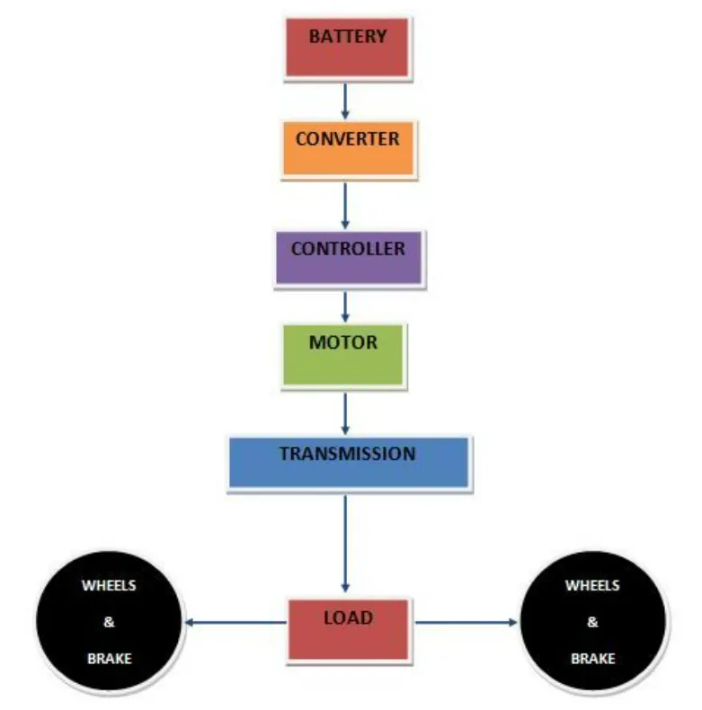
Based on the calculations done in 6A.
Force required to push/pull the aircraft =19.508 KN
Power required =135.478 kw
Let us assume,
The Radius of the Tyre for the Tug - 25inches =0.635m
Gear ratio=8
Transmission Effeciency (nt) =87%
Motor Efficiency (nm)=95%
then,
Torque required for the wheels (Tw)=Total Force *Radius in meters
=19.508 *0.635
=12.387KNm
Motor Torque-Wheel torque/(Gear ratio'nt)
=12.387/(8 0.87)
=1.778KNm
For nm =95%. The required motor Torque (Tm)= 1.778/0.95 =1.871 kNm
Similarly. The total power required by the motor considering all the efficiencies (Pt) = 135.478/(0.87*0.95)=163.917Kw
Let us assume the towing operation was done for a 15 minutes (0.25Hrs) duration.
Then, Total Energy consumed = 163.917* 0.25=40.98 KWh
If we consider the battery capacity=220 kw is used by the towing vehicle then. The duty cycle range to control the speed from O to max speed (3m/s) is given as
Duty Cycle (d)= (Required Power)/ (Rated power)= 163.917/220 =0.75
Therefore the controller will be able to provide a duty cycle ranging from 0 to 75% in order to control the towing speed.
Simulink Diagram of powertrain:
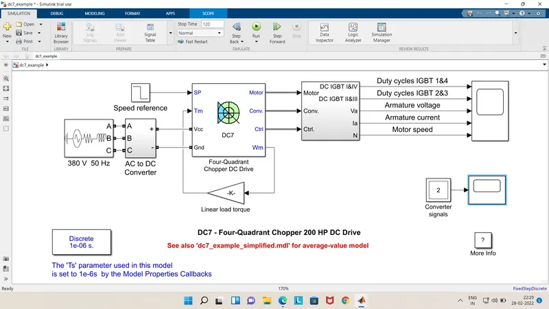
Output:
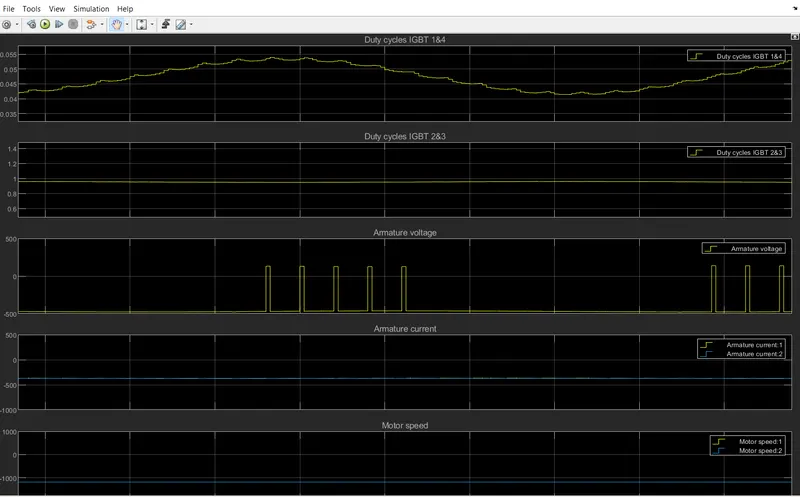
B. Designing the parameters in excel sheet.
Reference: -
1) Wikipedia
2)https://mediawiki.ivao.aero/index.php?title-Standard_aircraft_weight