Week -2
AIM:
To make a Simulink Model of Door Bell using Solenoid Block,
SOLENOID:
A Solenoid is a type of electromagnet, the purpose of which is to generate a controlled magnetic field through a coil wound into a tightly packed helix. The coil can be arranged to produce a uniform magnetic field in a volume of space when a current is pass through it. The term solenoid was coined in1823 by Andre Marie Ampere to designate a helical coil in Engineering the term may also refer to variety y of transducer device that convert energy into linear motion. The term is also often use to refer to a solenoid valve, an integrated device containing an electromechanical solenoid which actuate either a pneumatic value or hydraulic valve, or a solenoid switch, which is specific type of Relay that internally uses ari electromagnetic solenoid to operate an electric switch for example an automobile starter solenoid or linear solenoid, solenoid bolts, a type of electromechanical locking mechanism, also exist in electromagnetic technology, a solenoid is an actuator assembly with a sliding ferromagnetic plunger inside the coil. Without power, the plunger extends for part of its length outside the coil applying power pulls the plunger into the coil, Electromagnet with the fix core is not considered solenoids.
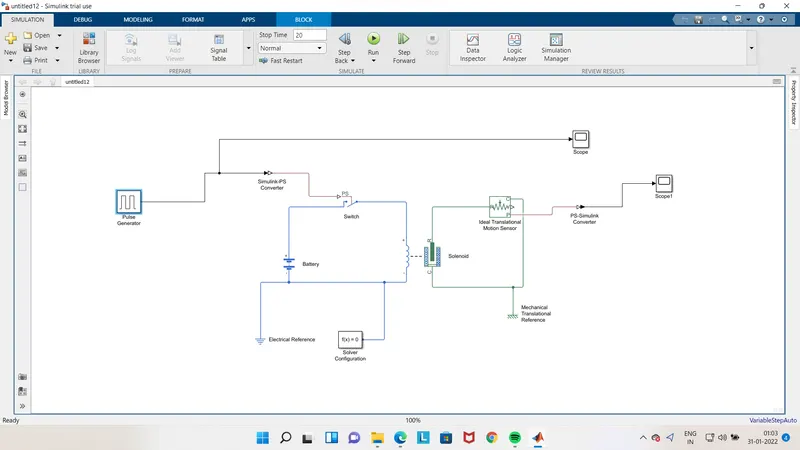
GIVEN CONDITION: IN the arrangement when the switch is closed the electromagnet receives electrical power from the Battery and pulls the metal arm to hit the bell producing sound by creating a situation where the switch is closed for 2 secs and then released.
We have used the following Blocks in the model
1 Pulse Generator:
The Pulse Generator block generates square wave pulses at regular intervals. The block waveform parameters, Amplitude, Pulse Width, Period, and Phase delay, determine the shape of the output waveform. The following diagram shows how each parameter affects the waveform
2 Battery
In Battery positive terminal is connected with switch and negative terminal is connected to "Electric Reference.
3 switch
The switch Block model a switch is controlled by an external physical signal.
4. Solenoid Block:
Solenoid Block is connected with Switch and Battery and electrical circuit will be formed.
The Solenoid Block represents the Electrical characteristics and generated force for the solenoid in the following figure:
The return spring is optional. To remove the effects of this spring from the model, set the spring constant parameter as from 0 to 10.
To show the direction in which the solenoid acts the block icon changes dynamically based on value of the Motion direction under
excitation parameter.
The Port 'C' is connected with Mechanical Translation reference
5. Ideal Translation Motion Sensor Block
Ideal Translation Motion Sensor Block is connected with Solenoid Block R to observe the Physical movement of the Plunger.
Connections R and Care mechanical translational conserving ports that connect the block to the nodes whose motion is being monitored Connections V and P are physical signal output ports for velocity and position, respectively
The block positive direction is from port R to port C. This means that the velocity is measured as v vR-VC, where VR, vC are the absolute velocities at ports R and C, respectively.
Port C is connected with Mechanical translational reference.
6. Scope:
Scope is connected with Ideal Translation Motion Sensor to get the output. The real-time Scope block acquires data in chunks of size Number of samples from the real-time application that is executing on the target computer.
7. PS-Simulink Converter:
The PS-Simulink Converter block converts a physical signal into a Simulink output signal. Use this block to connect outputs of a Physical Network diagram to Simulink scopes or other Simulink blocks.
8. Simulink-Ps Converter:
This Block convert simulink signals into physical signal for operational use in Model
Simulink-PS Converter
9. Electrical Reference Block:
The Electrical Reference block represents an electrical ground Electrical conserving parts of all the blocks that are directly connected to ground must be connected to an Electrical Reference block. A model with electrical elements must contain at least one Electrical Reference
10 Mechanical Translation Reference Block:
The Mechanical Rotational Reference block represents a reference point, or frame, for all mechanical rotational ports All rotational ports that are rigidly clamped to the frame (ground) must be connected to a Mechanical Rotational Reference block.
11. Solver Configuration:
Each physical network represented by a connected Simscape block diagram requires solver settings information for simulation. The Solver Configuration block specifies the solver parameters that your model needs before you can begin simulation.
OBJECTIVES:
For DoorBell- Create a situation where the switch is closed for 2 sec and then released. Observe the physical movement of the plunger.
EXPLANATION:
1. From the above governing circuit of a DoorBell, we know that we need a switch, solenoid, battery and a plunger.
2. So, in order to get these entire component in simulink model we have to select the block that perform same action what the above device perform.
3. Now first a "Solenoid block" is taken to represent a solenoid in the model, then to represent battery we have taken "Battery Block from the library Browser.
4. Then this "Solenoid Block" & "Battery Block" are connected to each other via positive and negative terminals. 5. A "Switch Block is placed between "Solenoid Blocks" and "Battery Block "and is connected with both Blocks.
6. Now for switch to operate we need to provide Physical signal through "PS" port in the "Switch Block: The provided physical
should be greater than the threshold of the switch, for switch being close, or else it will be open.
signal
7. Now this whole Battery Switch and Solenoid path is connected to an "Electric Reference Block" which represents earthing of the circuit. This "Electric Reference Block should be connected to the negative terminal of "Battery Block
8. Then in the solenoid block "R" and C are two variable which represent Plunger and Fixed Point respectively.
9. Now the solenoid "R" is connected to "R" of "Ideal Translation Motion Sensor Block which senses the position of plunger in the Solenoid Block and gives the Output
10. Now in the "Ideal Translation Motion Sensor Block the output are given as "V" & "P" which represent the velocity and position of the plunger. Since we are only interested in knowing the change in position of the plunger, so we need only results of "P" output.
11. Now "C in the "Ideal Translation Motion Sensor Block" is a mechanical translation conserving port, which means that the mechanical process starts from "R" and end at "C" and again it start at "R" and the cycle goes on.
12. So "C" in the "Ideal translation Motion sensor block" is connected to "Mechanical Translation Reference which represents a fix point where it is rigidly clamped in real time.
13. Similarly "C" of the solenoid block is also connected to the same "Mechanical Translation Reference as fixed point for solenoid.
14. Since we position of the plunger as output from "Ideal Translation Sensor Block we have connected port"p" to a "PS-Simulink Converter' where the Physical value from port 'P' are converted into Simulink value, and then this 'PS-Simulink Converter' is connected to 'Scope Block' which will generate a graph for change in position of Plunger from port 'P' of 'Ideal Translation Motion Sensor Block
15. Now to provide a physical signal for operating the switch, we have used a "Pulse Generator Block, which generates a continuoust.
16. From the above figure we can observe we have given period value as "4" pulse width as '50, phase delay as '2' and Amplitude by default is 'T' we have not changed it. This means that initially the Pulse will be Zero, Since we have given Phase Delay of "2" so till 2 sec the Pulse will be Zero and at the end of 2 sec the Pulse will start rising from Zero to 1, Since we have given Amplitude as "1" and then now the Pulse width will be Half of Period, So for the next 2 seconds the Pulse will be at Amplitude "1" only, then it will again come down to zero at 4th Second and then it will be Zero. So, after these 4 seconds period again the pulse will be generated and thus cycle continues.
17. From starting to ending of the Pulse it will take 4 sec of time period in which only for 2 secs the Amplitude will be "1" and for rest of time it will be Zero. So, after these 4 secs period again the Pulse will be generated and thus Cycle continues.
18. To this "Pulse Generator" a "Scope Block" is connected to see how the Pulse is generated.
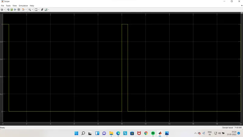
19. The above figure is obtained by running the Simulink Model and double clicking the "Scopel Block". This figure shows how the Pulse is generated and in this figure the X-axis represents the "Time" and Y-axis represents the "Amplitude.
s mentioned in the point no.18, the Pulse has started from 2 sec and ending at 6 sec which is nothing but a time period of 2 secs.
20. Thus, this represents that when amplitude is 1, the switch will be close and current will start flowing and when it is zero the switch will open and current stop flowing. Since our objective is only to see the change in position of Plunger when Switch is Close for 2 sec, so we have the Amplitude as 1 for 2 sec in the Pulse generator by making the Pulse width half of the period in the inputs fir "Pulse Generator Block".
21. Since the Pulse that is coming from "Pulse Generator Block" is a Simulink value, so to convert this value into Physical value we have used "Simulink-PS Converter Block, since Switch only takes Physical value as Inputs.
22. As mention above, the port "P" of "Ideal Translation Motion Sensor Block" is connected to another "Scope2 Block" and a "Solver Configuration Block" is also connected to this path which generates Equations and solves the whole Model internally to give the results of the Whole Simulink Model output.
23. Now Run the Model and Double click on the "Scope2 Block" which is connected to "Ideal Translation Motion Sensor Block" to get the results.
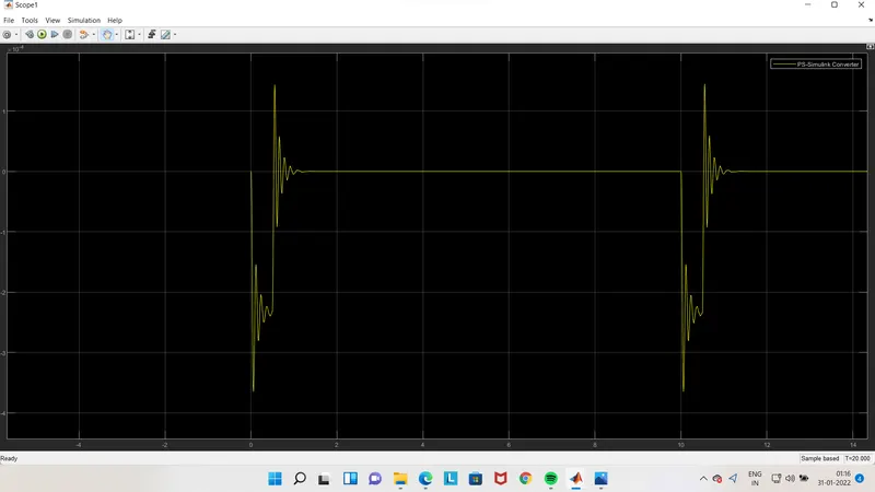
24. We will get the above Graph as the result when we double click on "Scope2 Block". Here X-axis Represent the Time and the Y-axis represent position of Plunger in mm.
25. From the above figure we can observe that the initial position of the Plunger is at "5mm" as from Pulse generator Block, a Pulse generated at 2, so in the position of the Plunger is also changing at time 2 seconds and time till which the Pulse Amplitude is T till that time plunger is also at the same position after the change from initial position.
26. Again, as the Amplitude of the Pulse become zero, the Plunger returns to the Original position back again and as the pulse cycle goes on. Plunger is also at same position after the change from initial position.
27. We can also observe that when there is change in position of the Plunger, there is some Wave form at the start of change in position. This is due to recoil of spring, each time when the Plunger is moving. So to reduce this, in the "Solenoid Block" we can reduce the spring constant value and increase the Damping Coefficient. This will reduce the Waves that are being formed and we will get a smooth graph.
28. The above figure is a smoother graph than previous one. This was done by changing the value of spring constant and Damping Coefficient in the "Solenoid Block".
OUTPUT:
CONCLUSION:
1.The Physical movement of the Plunger of solenoid was observed when switch is close for 2 seconds.
2.Simulink particularly helps to improve the performance by Analyzing it on plot and changing the suitable configuration, as in above case of Solenoid operated bell "Spring constant" and "Damping was varied as shown above.
2.use a thermistor to sense the temperature of a heater & turn on or tum off the fan with signal builder
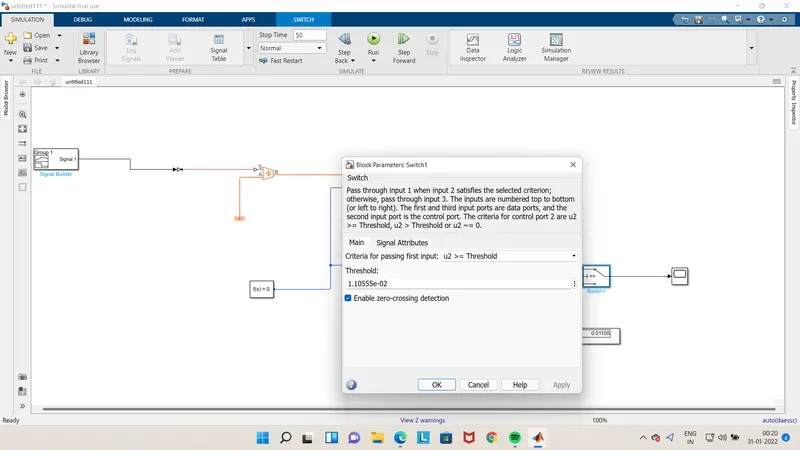
This figure shows the representation of thermistor connection which senses the temperature of a heater and passes the signal to a switch where a threshold limit is already set. If the temperature is above or equal to the threshold limit, then it gives "1" as output which is "Switch On". If the temperature is below the threshold limit, then it will give "O" as output which means "Switch Off". The input signal is generated with the help of a "Signal Builder" block . This signal is created according to the conditions given in this challenge. The conditions
Temperature source: 20 °C from 0 to 10 seconds
27 °C from 10 to 30 seconds
23 C from 30 to 50 seconds
Fan conditions: ON if the temperature above 25 C. OFF otherwise
Here the temperature is converted in Kelvin from degree Celcius because the signal converter does not take "C value as input. I also have to set the signal unit as "Kelvin in Simulink-PS Converter.
The formula for conversion: 1°C 273,15 K
The Signal 1 is:
From 0-10 sec- Temperature is 293.15 K
From 10-30 sec- Temperature is 300.15 K
From 30-50 sec- Temperature is 296.15 K
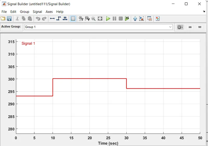
input signal created on signal builder
switch(threeshold value set here)
Model explaination:
1. At first, the signal is created in "Signal Builder" and further passes to "Simulink-PS Converter" to convert the input signal into the physical signal.
2. This physical signal is connected to a block "Controlled Temperature Source". This block is connected to the thermistor and a
"Thermal Reference" block.
3. The thermistor is a part of an electric circuit where a battery, a voltage sensor, a resistor connected parallel to the voltage sensor, an electrical reference are connected to make a complete circuit. A solver configuration is connected to that electrical circuit to solve all parameters before the beginning of the simulation.
4. The voltage sensor senses the temperature in the form of voltage and sends the data to its port "V".
5. From this port, we get our output and send it to two different "PS-Simulink Converter".
6. From converter-1, the signal is sent to the threshold switch. In the switch, the threshold limit is set to 1.10555e-02. If the temperature
is above or equal to the threshold limit, then it gives "1" as output which is "Switch On". If the temperature is below the threshold limit, then it will give "O" as output which means "Switch Off". The input signal is generated with the help of a "Signal Builder" block .
7. The switch is connected to the scope where we can see our output plot.
8. From converter-2, it converts the physical signal into a Simulink signal and sends the voltage data from
This display gives us the threshold value of voltage. This value is set in the switch.
Output:
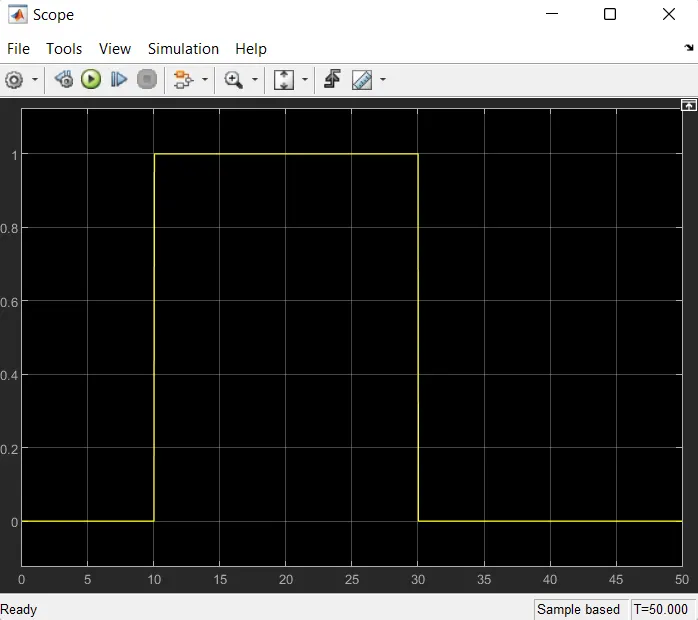
It can be seen that the value of the signal is "O" from 0-10 sec because in this time the temperature was 20°C which is below 25°C means "Switch off the fan". After that, the signal value gives "1" as output from 10-30 sec because in this time the temperature was 27°C which is above 25°C means "Switch on the fan". The value of the signal is again goes to "O" from 30-50 sec because in this time the temperature was 23°C which is below 25°C means "Switch off the fan
Now it is clear that our model is correct and fulfills all the input conditions.
Note: Simulink models of both objectives and outputs along with other data are attached in the attachment box. Please find those.
References:
https://wonderopolis.org/wonder/how-does-a-doorbell-work
https://simple.wikipedia.org/wiki/Solenoid
https://www.google.com/url?
sa=t&rct=j&q=&esrc=s&source=web&cd=&cad=rja&uact=8&ved=2ahUKEwitjOyii9PvAhVibSsKHbkwDkIQFjARegQIBhAD&url=https:/% 2Fwww.electrical4u.com/thermistor/&usg=AOvVaw3PSJmK9s3wuui1kpdkA-Al
https://www.mathworks.com/help/releases/R2018a/physmod/elec/ref/thermistor.html