Week - 4
AIM:- Implement control logic of a "washing machine using Stateflow.
OBJECTIVE:
1. Implement control logic of a washing machine using Stateflow as per given sequence:
• If the power supply is available, the system gets activated • If the Water supply is not available, stop the process & indicate through
• Soaking time should be 200s followed by washing time of 100s.
• Then rinsing happens for next 20s & dryer runs for 50s
After all the processes have completed turn ON the finished LED
EXPLAINATION:
State Flow
State Flow provides a graphical language that includes state transition diagrams, flow charts, state transition tables, and truth tables. By using State Flow to describe how MATLAB algorithms and Simulink models react to input signals, events, and time-based conditions.
State Flow is a Simulink tool to implement the state machine. Here, the model system logic of a Washing Machine using State Flow has been done.
Control Logic
Control Logic is model system logic using State machines, Flowchart and Truth Tables.
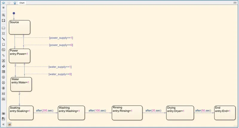
flowchart of washing machine
TRUTH TABLE:
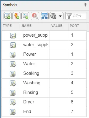
. Give the input values for turning ON or OFF for the Power Supply and Water Supply.
Condition:
If value = 1, Power and Water Supply will turn ON.
If value = 0, Power and Water Supply will turn OFF.
. Use 'display' block and 'Lamp' indicator to display the result.
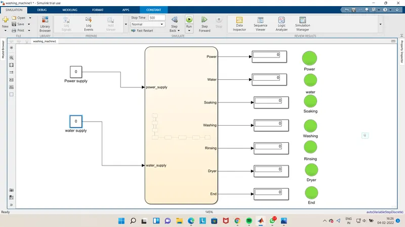
OUTPUT:
TASK 1:
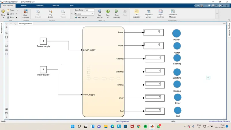
Control Logic of a Washing Machine using State Flow has been implemented.
Case1:
If the Power Source - 0. Power Supply is not available and system will not be activated.
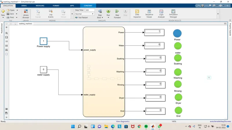
Case2:
If the Power Source=1 and Water Source =0, then the Power Supply will turn ON and Water Supply will not be available. So system
will not be activated.
Case3:
If the Power Source-1 and Water Supply-1, then Power Supply will turn ON and Water Supply will be available. system will be and after all process completed, lamp will turn ON activated.
Conclusion:
control logic of a "washing machine" using Stateflow as per given sequence is implimented properly.
AIM-2:
Make a Simulink chart for the "Gear shift" logic as per below conditions
Speed Range(kmph) Gear
O to 15 1
16 to 25 2
26 to 40 3
41 to 60 4
Above 61 5
Give speed input while the simulation is running & display the gear number.
REQUIREMENTS
Simulink is a graphical user interface for modeling and simulation of block schematics. The core of the Matlab is used to compute the simulating results, Simulink is primarily used for modeling dynamic systems. Simulink's libraries offer a plenty of blocks useful for modeling complements.
PROCEDURE
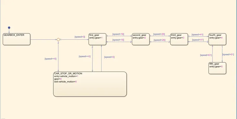
The first step is to create a stateflow chart in the simulink environment. It is done by double clicking on the simulink environment andsearching for 'chart or draging it from the simulink library.
• Then we will create the 5 states for the five gear shifts with output arguements as the gear number for the respective states. Also the conditions for the transition from one gear state to the other is provided as shown in the figure.
. After that we will define a default state 'GEARBOX_ENTER which is inturn connected to a junction. From this junction, we are giving another state called 'CAR STOP_OR_MOTION for knowing whether the car is in motion or not. If it is in motion gear shift has to make, which has to connected to the first gear. Else, it has to display 0 in the display block.
. Now we will define the input and output to the chart. The input has to be made convenient in such a way that the user can provide the input during the simulation. So i made use of a slider gain block alon with a constant block. For clarity of understanding, we will connect a custom gauge block as the odometre to the slider gain.
• The output is conected to 2 display blocks-vehicle stop/motion and gear panel. The former is for displaying whether the gearbox is engaged or not and the later is for knowing which gear is in engagement.
NOTE-Here the stop time is given as inf (e.infinity) Because the user can provide whichever speed value as many times as he wants during the simulation time, so the simulation can be long enough
1.WHEN THE SPEED IS 0 (i.e. vehicle stop condition) AND NO GEAR SHIFT IS MADE.
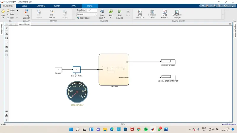
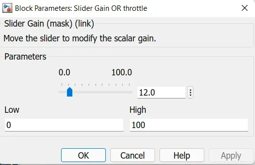
2. WHEN THE SPEED IS 12Kmph, GEAR SHIFT IS MADE TO 1 AND THE VEHCLE IS IN MOTION3.WHEN THE SPEED IS 23Kmph, GEAR SHIFT IS MADE TO 2 AND THE VEHCLE IS IN MOTION.
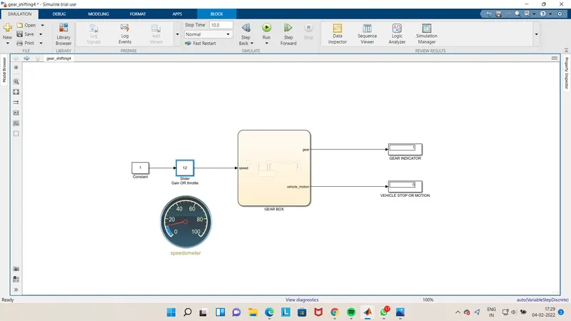
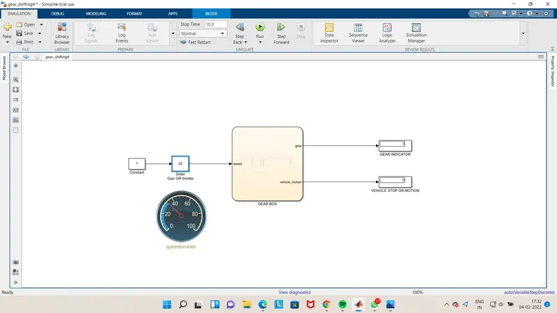
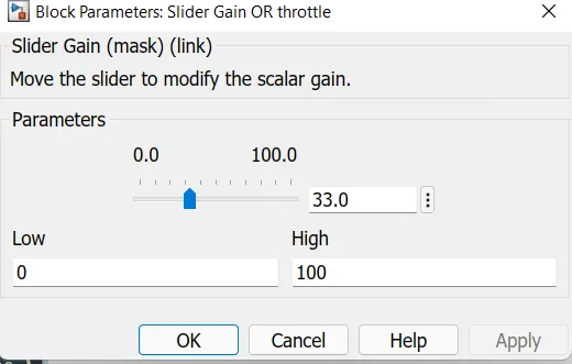
3. WHEN THE SPEED IS 33Kmph, GEAR SHIFT IS MADE TO 3 AND THE VEHCLE IS IN MOTION.
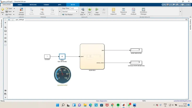
4.WHEN THE SPEED IS 43Kmph, GEAR SHIFT IS MADE TO 4 AND THE VEHCLE IS IN MOTION.
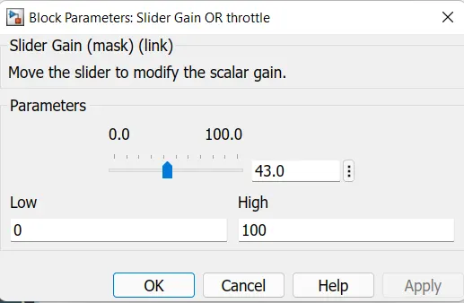
5.WHEN THE SPEED IS 72Kmph, GEAR SHIFT IS MADE TO 5 AND THE VEHCLE IS IN MOTION.
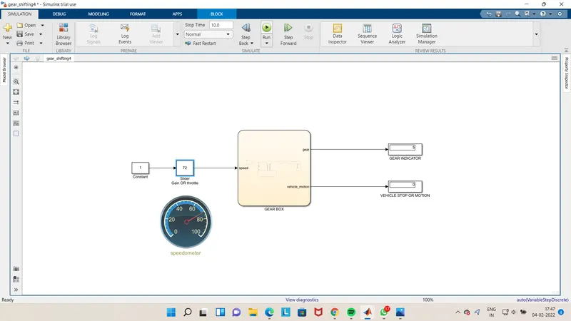
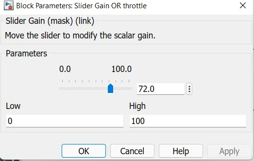
OUTPUT:- You can see the graph is increasing as per the throttle input. The gear shift is made from 0 to 5. The vehicle stop is symbolised using o and vehicle in motion by 1.
RESULT:
The simulink design using stateflow chart for the gear shift is successfully made.