Week-4 Challenge WOT Condition Part-2
Question - 1
What is the difference between mapped and dynamic model of engine, motor and generator? How can you change model type?
Mapped engine:
- In Mapped models the data used for the operation and simulation are to be entered in the form of Lookup table.
- The lookup table which would be configured with the operational parts and the analysis would br formed.
- The advantage is specification/ lookup table data is available with us the simulatin become easier and it gives the result on the basis of dataa interpreted.
- the disadvantage is more data has to be collected and some assumption might also have to be taken.
Dynamic engine:
- In Dynamic Model it understands the behavior of the ookup Table part/element and then it behaves accordingly. It gives operational detailed analysis for the variations entered by us in the Specifications whereas it simulates according to real and dynamic operations.
- The advantage It operates dynamically depending on the situation of operation detailed data and specifications are not required and the simulation gives the detailed analysis of the components simulated.
- the disadvantage is Could not simulate as per our customized specifications.
Question - 2
How does the model calculate miles per gallon? Which factors are considered to model fuel flow?
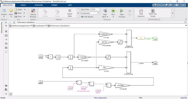
Conversion from Cubic Meter to gallon (m^3 to gallon),
As we know 264.172 US Gallons is 1000L
The reference model taken here for consideration is HEV and as it operates on both the Battery and the Fuel Injection Engine.
The final output/Fuel Efficiency is calculated by keeping in consideration of the Battery Output, Fuel Output and the Vehicle Speed/Kilometres Driven. Therefore the fuel efficiency is calculated and it is converted after the saturation thus the FE is calculated.
Question - 3
Run the HEV ReferenceApplication with WOT drive cycle. Change the grade and wind velocity in the environment block. Comment on the results.
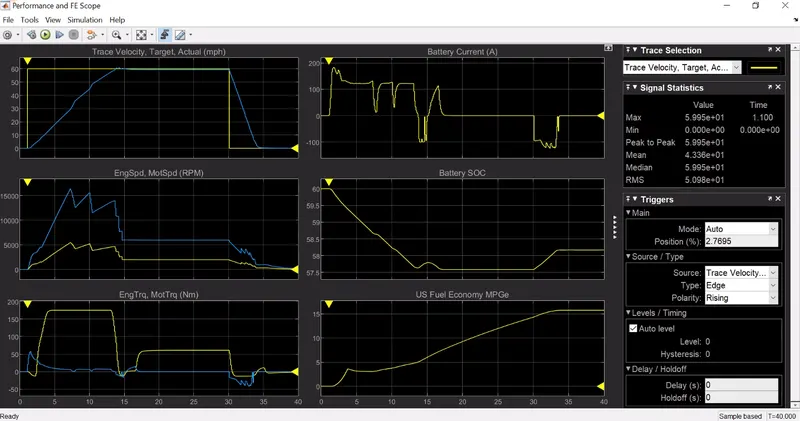
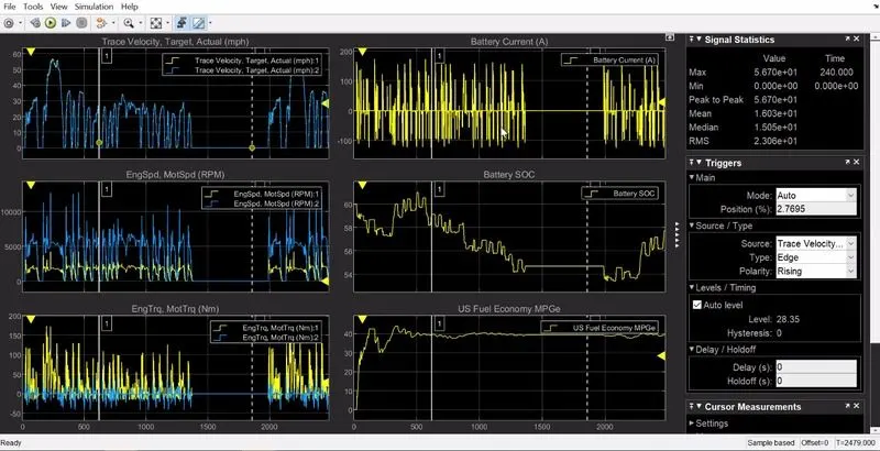
1. Plot 1 (Trace Velocity Target vs Actual) - Through this plot it is denoted that the desired Velocity has been met by the actual vehicle velocity. The desiered velocity was ranging at near about 60 mph but he actual velocity achieved was near to 60 mph.
2. Plot 2 (Engine Speed, Motor Speed) rpm - This plot gives the detailed analysis for the achieved Engine and Motor speed in rpm.the contribution of both the Power Generating sources for meeting the required Velocity.
3. Plot 3 (Engine Torque, Motor Torque and Generator Torque) Nm - This plot gives the detailed analysis of the Engine, Motor Torque
and Generator Torque.
4. Plot 4 (Battery Current) A- This plot denotes the power produced by the Battery and the readings are in Ampere.
5. Plot 5 (Battery SOC) - This plot denotes the State Of Charge of the battery, this denotes the range of charge used for the achievement of velocity.
6. Plot 6 (US Fuel Economy) MPGe - This is the Efficiency or the Range of the drive and the same is denoted in Miles Per Gallon equivalent.
WOT Cycle with changes in Grade and Wind Velocity.
Question - 4
Keeping all other parameters same. compare the simulated results of hybrid and pure electric powertrains.
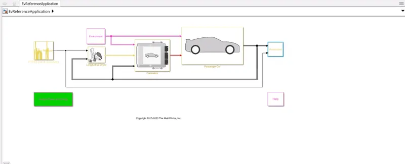
Below mentioned vehicle is simulated for the EV Reference
The Performance and FE Results obtained are appended as below,
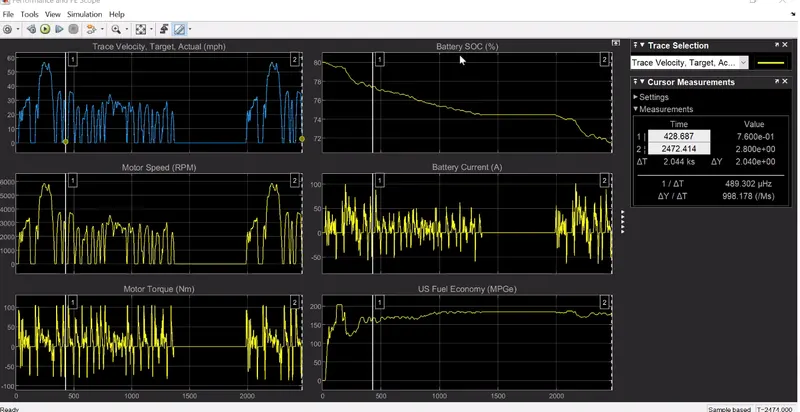
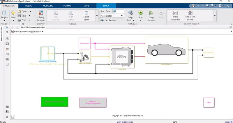
Vehicle is simulated by HEV Refernce:
The performe FE REsult obtained:
Conclusion:
The overall difference in both these simulations are their vehicle operations where the EV is completely operated on Battery as the Power Sorce and on the other hand the HEV has two power soures SI/CI Engine and Battery. The results obtained are varied and the parameters are also differenciated accordingly.