Project-1: Powertrain for aircraft in runways
1)Search and list out the total weight of various types of aircrafts.
Aircraft gross weight is the total aircraft weight at any time during flight or groung operation. The gross weight can decrease during a flight due to fuel consumption or it may vary during refuelling or payload dropping. Below is the list of aircraft with total weights:
| AIRCRAFT NAME | AIRCRAFT GROSS WEIGHT |
| Antanov AN-225 | 640,000 kg |
| Airbus A380-800 | 575,000 kg |
| Boeing 747-800 | 447,700 kg |
| Airbus A340-500 | 372,000 kg |
| Boeing 787-10 | 254,000 kg |
| Boeing 737-900 | 85,000 kg |
| Airbus A320-100 | 68,000 kg |
| Embraer 190 | 48,000 kg |
| Gulfstream G650 | 45,200 kg |
| Bombardier CRJ900 | 36,500 kg |
| Cessna Citation CJ4 | 7,800 kg |
| Learjet 75 | 9,700 kg |
| Beechcraft King Air B100 | 5,400 kg |
| Bombardier Q400 | 28,000 kg |
| Diamond DA50 RG | 2,000 kg |
| Beechcraft Bonanza G36 | 1,660 kg |
| Cessna 206H | 1,630 kg |
| Sirrus SR22 | 1,630 kg |
| Cessna 172R | 1,100 kg |
2)Is there any difference between ground speed and air speed?
Ground Speed-
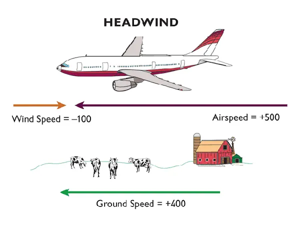
It is the actual speed of the aircraft over the ground and it is the result of the effect of wind on the aircraft. Ground speed is used to estimate the time taken to reach the destination. For example, if an airplane is moving with 110 knots into a 12 knot head wind, the ground speed will be 98 knots. Head wind is the wind opposing the movement of aircraft.
Air Speed-
1) Indicated air speed- It is the speed that the aircraft's ' airspeed indicator' display. It is the measure of the speed of the airflow over the aircraft's wings.
2) True air speed- It is the indicated air speed adjusted for altitude and non- standard temperature and theoratically, how fast an aircraft would be flying in a no wind condition.
3)Why is it not recommended to use aircraft engine power to move it on the ground at Airport?
When the aircraft is parked on the ground, it requires power to run aircraft support system such as electricity for light and avionics, airconditioning, hydraulics and HVAC system. The power required to run these auxilliaries is fed by auxilliary processing unit installed at the airports or a special small engine is installed on the aircraft to run these auxiliaries.
Now, if engine power is used to run these auxiliaries and kept on for a long period of time on the ground, there is a risk of FOD damage. FOD stands for foriegn object debris which can be sucked in by the wind turbulence of aircraft engine. Also , it is extremely dangerous to leave engine running with people working around the airplane.
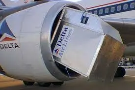 NO ITEM TOO SMALL FOR AIRCRAFT ENGINES.
4)How an aircraft is pushed to runway when its ready to take off?
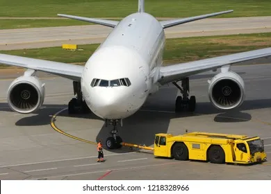
Passenger aircraft are pushed away from the passenger loading gate by a tug. A tug is a machine, which has some form of power such as internal combustion engine or a battery. An aircraft is being pushed backwards and persons employed to look at each tip of the wing, so that they don't touch anything. So, an aircraft might be pushed backwards off the ramp or on to the taxi way.
5)Learn about take off power, tyre design, rolling resistance, tyre pressure, brake forces when landing.
TAKE OFF PERFORMANCE CALCULATIONS-
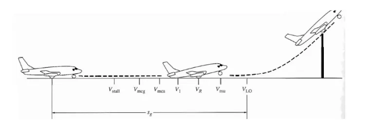
The aircraft covers a distance from starting position on the runway to a distance where it starts lifting in the air. This distance is known Ground roll. The distance when the aircraft completely goes airborne is also calculated as well. So, the total take off distance consist of ground roll as well as the distance taken by the aircraft to completely get airborne.
Total take off Distance= ground roll(Sg)+ distance in air(Sa)
Talking about the velocities, as the aircraft starts from the zero velocity, it first reaches to the stall velocity(Vs). Stall velocity is the minimum speed needed by the aircraft to generate lift. Stall speed depends on various factors like weight of the aircraft, dimensions, altitude and weather conditions.
After this, aircraft must reach some minimum control speed. This is the speed at which lateral and directional control of the aircraft can be maintained if by chance one engine fails. So, it is possible to maintain directional control only using aerodynamic control along the ground(Vmcg).
Further, if the aircraft is in air, the minimum speed required for yaw control if by chance any engine fails of multi-engine aircrafts is known as minimum speed control in air(Vmca).
After this, aircrafts acclerates to final velocity which is known as the Decision Speed(V1), the speed at which pilot can successfuly continue takeoff even though an engine fails at this point. Decision speed also decides that if the speed is less at this point or less than decision speed, then takeoff must be stopped by chance an engine fails.
Takeoff Rotational Speed(Vr)- At this speed, pilot increase the angle of attack by initiating the elevator and also to overcome the weight.
Then the aircraft reaches to the minimum unstick speed(Vmus), the speed at which or minimum speed required to take off. Finally, the speed at which the aircraft goes airborne is the Lift off Speed(Vlo). The total distance upto this point is ground roll (Sg).
Also, Vlo= 1.1* Vs
NOW, CALCULATING THE TAKE OFF PERFORMANCE:
m* dv/dt= T-D-R
ALSO,R=μr(W-L)
m*dv/dt= T-D-μr(W-L)
Air drag and rolling resistance (R) caused by the friction between tires and the ground.
1) TIRE DESIGN OF AIRCRAFT:
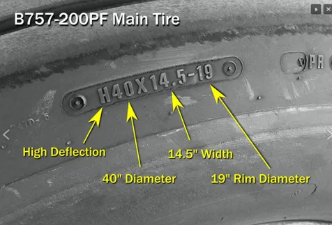
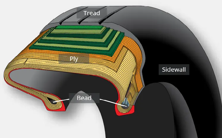
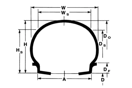
W- Section Width ; Ws- shoulder width; H- section height; Hs- Shoulder section height
D- Rim ledge diameter; Df- Rime flange outer diameter; Do- outside dia; Ds- Shoulder dia
Formula for calculations:
Ws= 0.90 * W
Ds= 2*(0.9H)+D
H= (Do-D)/2
Hs=(Ds- D)/2
Static load radius(SLR)= (Dm/2)-d[(Dm-Df)/2]
Dm- Mean overall tire diameter
Df- Rim flange outer diameter
d- percent tire deflection
2) ROLLING RESISTANCE CALCULATIONS:
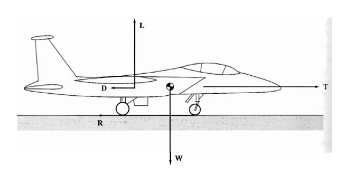
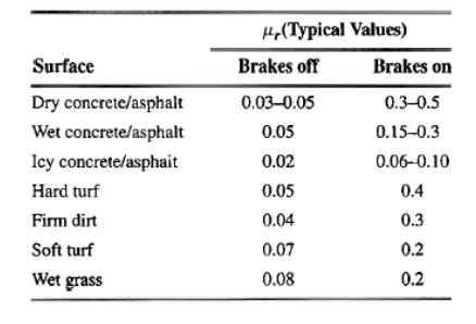
The value of rolling resistance(R) depends upon the total weight(W) of the aircraft, road conditions( coefficient of rolling friction, μr) and lift(L) of the aircraft. The lift should overcome the total weight while rolling on the ground.
R=μr(W-L)
The vairous values of coefficient of friction:
3)TYRE PRESSURE:
Aviation tires has to deal with high load and extreme speed. So they need a bit more care. Nitrogen is most of time used in commercial operations instead of air. Nitorgen is filled to deal with extreme changes in ambient temperature and pressure during flight to minimize expansion and contraction. It eliminates the possibility of explosion.
Airliners aircraft tires have the ability to sustain the pressure as high as 55 bar or 800 psi before bursting. Generally, aircraft tires operates at 200 psi or 14 bar for airliners, even more for other jets. The landing gear is typically inflated to 232 psi or 16 bar. Tail bumper tires are even more high as 294 psi or 20.3 bar.
4)Brake force during landing:
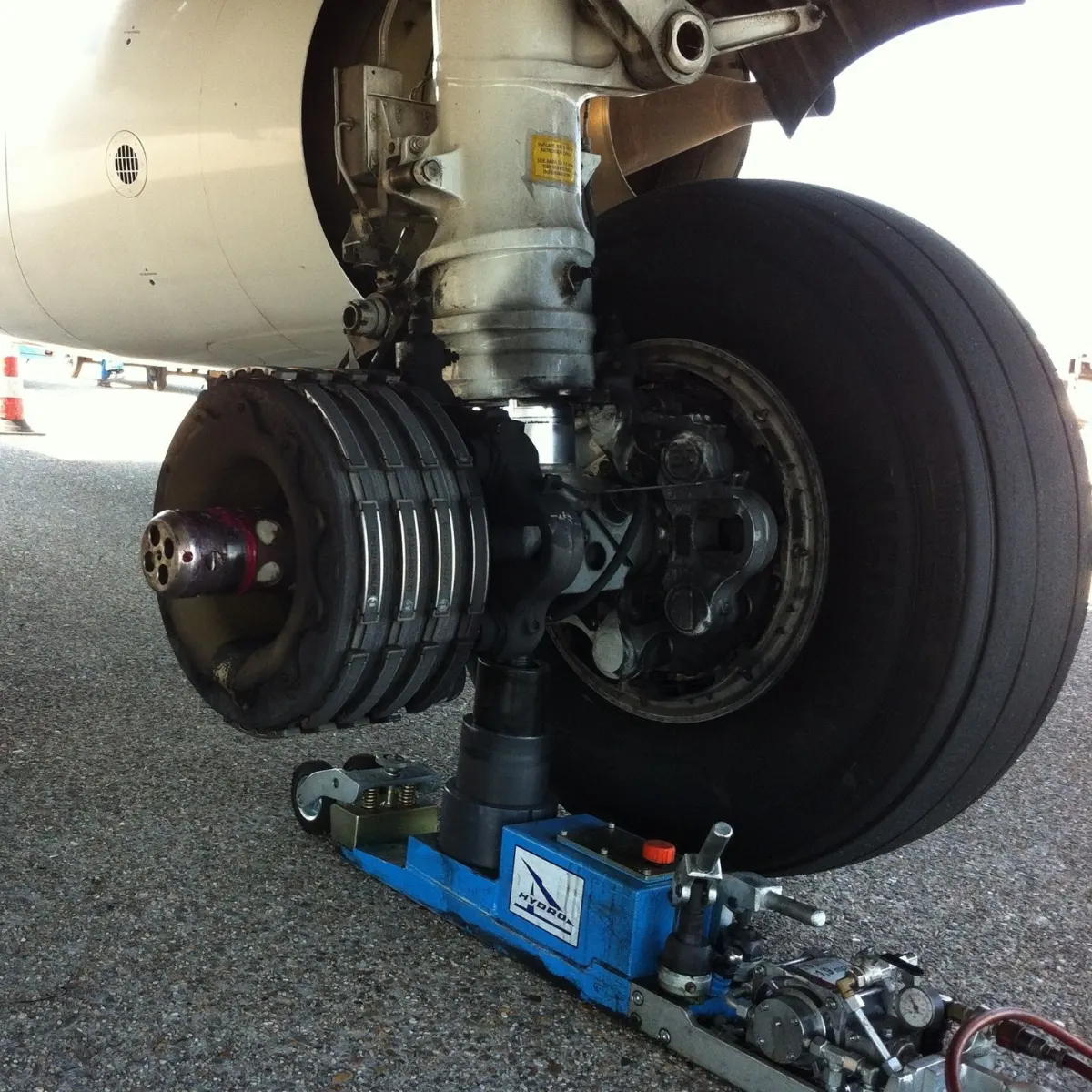
1)DISC BRAKES: Braking force is a primary system that stops an aircraft on the runway after landing. This braking force is generated by the aircraft brakes, which are actually energy absorbing devices which removes ample amount of kinetic energy gained by the momentum of the aircraft. Brakes can be termed as energy converter as well. They convert kinetic energy gained through the momentum to heat form through the friction of the rolling tires on the runway surface. These are massive structures built to withstand massive forces and incredible energy level.
Modern era aircraft brakes are made of steel with carbon disks. Carbons can absorb energy very efficiently in comparison to the steel disks earlier used on steel brakes. Carbons can operate at very high temperatures and become even more effective after heating. Disc brakes are operated hydraullically or pneumatically.
2) THRUST REVERSERS: These brakes are totally dependent on the aircraft engine. It is control system found in many airplanes with jet engines. This control system is used to reverse the airflow of the aircraft partially. Pilots usually engage reverse thrust to slow down the airliner just before landing.
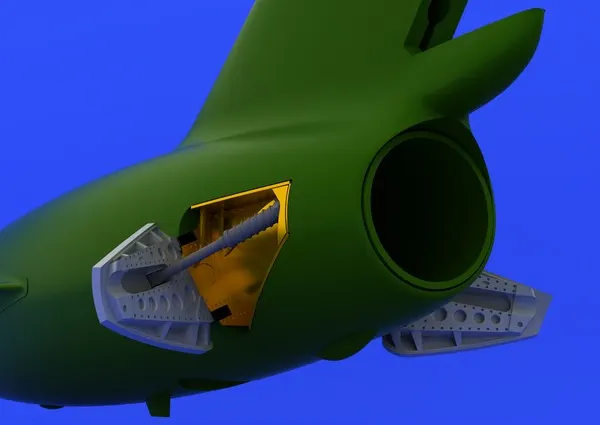
3) AIR BRAKES: These are also known as speed brakes. It is a kind of flight control surface which is used to increase the drag on the aircraft. With the increase in drag, the speed of the aircraft will be slow down in the air and this technique is also employed before landing or afterwards, which helps in decelerating the aircraft.
PART B:
A) With necessary assumptions, calculate the force and power required to push / pull an aircraft by a towing vehicle.
Two kinds of forces will be come into the effect while pushing or pulling the aircraft with the help of towing vehicle: 1) rolling resistance force for aircraft as well as the towing vehicle
2) airdrag force ( it will be negligible as the towing will take place in a very slow manner).
so, the net force F= rolling resistance force(aircraft)+rolling resistance force(towing vehicle)
so, rolling resistance force for aircraft will be = μr(m.g)
let the gross weight of the aircraft be=50000kg
and rolling resistance coefficient, μr=0.03
so, rolling resistance force(aircraft )=0.03(50000*9.81)
=14715 N
calculating the rolling resistance for towing vehicle= μr(m.g)
=0.08(1500*9.81)= 1177.22 N
so, NET FORCE = 14715+1177.2= 15892.2 N
CALCULATING THE POWER REQUIRED FOR TOWING:
-it will depend upon the speed of the vehicle ; which is assumed as 10kmph
SO, power= force * velocity= 15892.2 * 2.77 m/s= 44021.4 watts= 44 kW(approx)
B. Develop the model for the calculated force and power using Simulink.
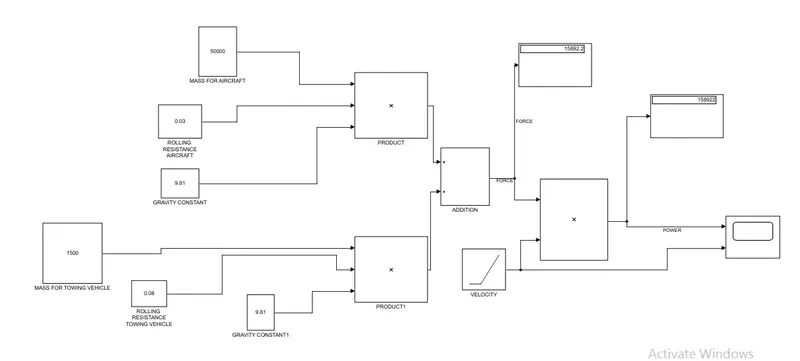
for the above simulink model, following are the blocks used:
- constant block
- product block
- addition block
- scope block
- display block
Also, the velocity is condered from 0 to 10 kmph and the power is hence, increased with increasing velocity.
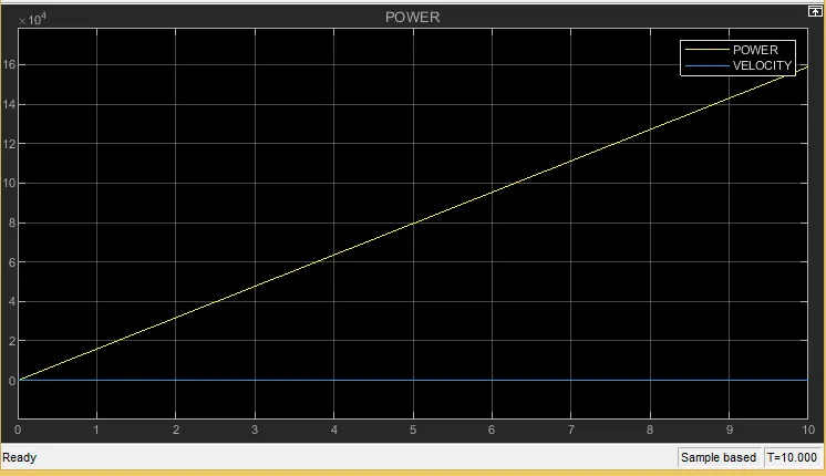
The netforce, i got is the same as in the written calculation,that is , 15892.2 N.
and the total power required for increasing velocity is = 159 kW(APPROX)
7. A. Design an electric powertrain with type of motor, it’s power rating, and energy requirement to fulfill aircraft towing application in Simulink. Estimate the duty cycle range to control the aircraft speed from zero to highest. Make all required assumptions. Prepare a table of assumed parameters. Draw a block diagram of powertrain.
TOWING VEHICLE ELECTRIC POWERTRAIN DESIGN:
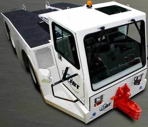
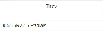
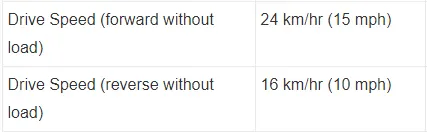
B600 MODEL SPECIFICATIONS:


ASSUMPTIONS TABLE:
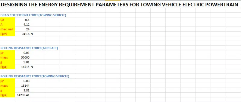
| AIRCRAFT GROSS WEIGHT | 50000 Kg |
| rolling resistance(aircraft) | 0.03 |
| GROSS VEHICLE WEIGHT | 18144 Kg |
| rolling resistance(vehicle) | 0.08 |
| frontal area (calculated) | 2.59 * 1.59= 4.12 m^2 |
| Drag force coefficient | 0.5 |
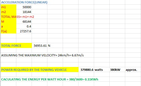
| Acceleration of vehicle | 0.4 m/s^2 |
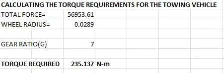
CALCULATING THE TIRE RADIUS:
RIM DIA= 22.5in=0.5715m
height of tire=65% of width of the tire= (65/100) * 365= 237.25mm
wheel dia= rim dia+2h= 0.5715+2(0.00023725)=0.578 m
TIRE RADIUS=0.578/2=0.289m
MOTOR SELECTION:
DUTY CYCLE ESTIMATION:
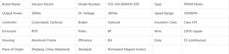
Input power= 500 kW
required output power= 380 kW
d= 380/500=0.76 or 76% duty cycle
BLOCK DIAGRAM REPRESENTATION OF ELECTRIC POWERTRAIN:
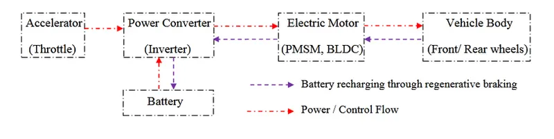
ELECTRIC POWERTRAIN FOR TOWING VEHICLE:
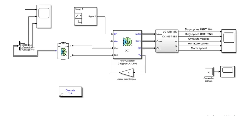
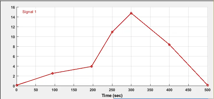
following is the drive cycle designed in the signal builder block:
SIMULATION RESULT:
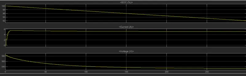
so, the simualation is carried out for 300 seconds and for that time, state of charge is depreciating upto 92% and then remaining constant . Also, with increase in the passage of time as well as during the acceleration, the maximum current is drawn and simulataneously is the graph for the voltage.