Project-1: Powertrain for aircraft in runways
MODULE1#
Part A:
1. Search and list out the total weight of various types of aircrafts.
2. Is there any difference between ground speed and air speed?
3. Why is it not recommended to use aircraft engine power to move it on the ground at Airport?
4. How an aircraft is pushed to runway when its ready to take off?
5. Learn about take off power, tyre design, Rolling resistance, tyre pressure, brake forces when landing.
Search and list out the total weight of various types of aircrafts.
The different terms represent different weights or masses. For each flight, the weights are taken into account for several reasons.
Manufacturer's empty weight (MEW)
Also called Manufacturer's Weight Empty (MWE) or Licensed Empty Weight
It is the weight of the aircraft "as built" and includes the weight of the structure, power plant, furnishings, installations, systems and other equipment that are considered an integral part of an aircraft.
This excludes any baggage, passengers, or usable fuel2.
Zero-fuel weight (ZFW)
This is the total weight of the airplane and all its contents (including unusable fuel), but excluding the total weight of the usable fuel on board.
As a flight progresses and fuel is consumed, the total weight of the airplane reduces, but the ZFW remains constant.
Maximum zero fuel weight (MZFW) is the maximum weight allowed before usable fuel and other specified usable agents (engine injection fluid, and other consumable propulsion agents) are loaded.
Operating empty weight (OEW) (Roughly equivalent to basic empty weight on light aircraft)
It is the basic weight of an aircraft including the crew, all fluids necessary for operation such as engine oil, engine coolant, water, unusable fuel and all operator items and equipment required for flight but excluding usable fuel and the payload.
It is the carrying capacity of an aircraft. It includes cargo, people, extra fuel. In the case of a commercial airliner, it may refer only to revenue-generating cargo or paying passengers.
Maximum takeoff weight (MTOW)
This is the maximum weight at which the pilot of the aircraft is allowed to attempt to take off.
Regulated takeoff weight (RTOW)
Depending on different factors (e.g. flap setting, altitude, air temperature, length of runway), RTOW or maximum permissible takeoff weight varies for each takeoff. It can never be higher than MTOW..
Maximum landing weight (MLW)
This maximum weight at which an aircraft is permitted to land3.
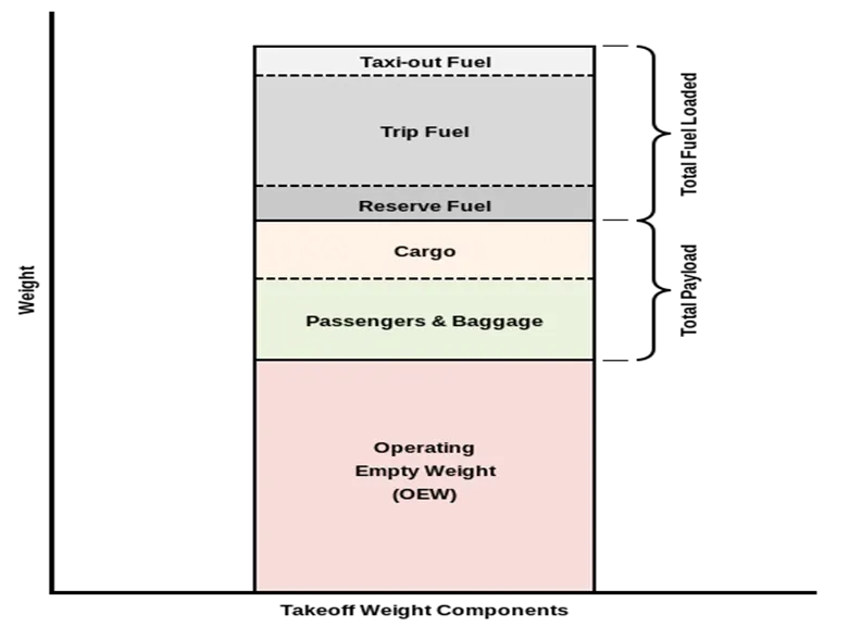
The following image depicts takeoff weight components.
Maximum ramp weight (MRW)
also called maximum taxi weight (MTW)
It is the maximum weight authorized for maneuvering (taxiing or towing) an aircraft on the ground.
It is the total aircraft weight at any moment during the flight or ground operation. This decreases during flight due to fuel and oil consumption.
Is there any difference between ground speed and air speed?
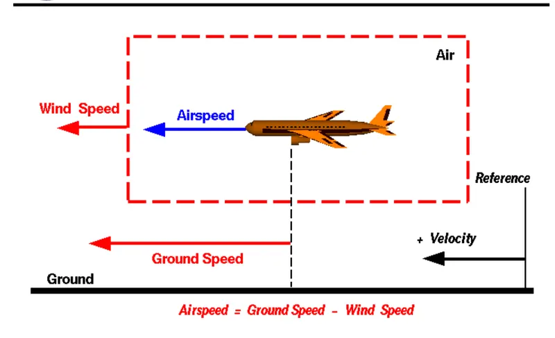
The relationship between airspeed and ground speed is fairly simple. Ground speed is simply the sum of airspeed and wind speed.
If the aircraft is flying in the same direction as the wind is blowing, the aircraft experiences tailwind, and its ground speed is higher than its airspeed. On the other hand, if the wind is blowing against the direction the aircraft is traveling in, the aircraft experiences headwind, and its ground speed is lower than its airspeed.
To give you an actual example, imagine an aircraft that cruises at an airspeed of 500 miles per hour that has to cover a ground distance of 2,000 miles.
If there is no wind at all, then both the aircraft’s airspeed and ground speed would be the same 500 miles per hour, and the aircraft would reach its destination in four hours.
If there was a 100 miles per hour headwind – wind blowing against the aircraft’s direction of travel – the aircraft would still be traveling at an airspeed of 500 miles per hour. However, its ground speed would be just 400 miles per hour (100 miles per hour slower than its airspeed). And as such, it would take the aircraft five hours to reach its destinations.
Finally, if there was a 100 miles per hour tailwind – wind blowing in the same direction as the aircraft’s travel – the aircraft would still be traveling at an airspeed of 500 miles per hour, but its ground speed would be 100 miles faster.
And, at 600 miles an hour, the aircraft would reach its destination in just three hours and twenty minutes.
The above is the reason why some flights go “out of their way” to avoid headwinds or catch tailwinds. And, why some flights might appear to be traveling at “supersonic speeds,” even though their airspeed – the speed that would actually matter in determining whether or not the flight truly is supersonic – is subsonic.
Why is it not recommended to use aircraft engine power to move it on the ground at Airport
High engine thrust during maintenance/ parking activity can cause considerable damage to airplanes and other elements in the airport environment.A towing vehicle must be required to over com the problem.
Airplanes get towed when the thrust of their engines creates a significant hazard to the immediate area surrounding them. Planes also get towed for maintenance purposes so pilots are not required to move the aircraft as airplane mechanics are trained in the use of the aircraft brakes while towing.
some of the terms must be noted here
Taxing is ground movement of aircraft with the help of engine power.

Towing is forward movement of aircraft with the help of a Towing tractor wihile aircraft engines is off.
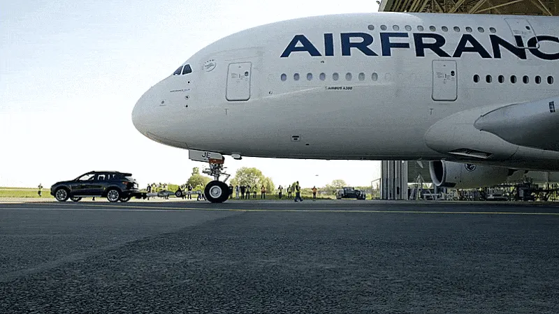
Pushback is reverse movement of aircraft with the help of a towing tractor generally away from the terminal building (since aircraft engines cant push the aircraft in reverse direction
How an aircraft is pushed to runway when its ready to take off
aircraft are pushed away from the passenger loading gate by a tug. This is a machine with wheels, some form of power such as an internal combustion engine, or a battery. When the large aircraft is being pushed backwards, there is someone on each wing tip. They are looking out to make sure nothing will touch the aircraft. The whole idea is to avoid expensive crunching noises
Learn about take off power, tyre design, rolling resistance, tyre pressure, brake forces when landing.
Taxiing refers to the movement of an aircraft on the ground, under its own power. The aircraft moves on wheels. An airplane uses taxiways to taxi from one place on an airport to another; for example, when moving from a terminal to the runway
Take off power
Takeoff is the phase of flight in which an aircraft goes through a transition from moving along the ground (taxiing) to flying in the air, usually starting on a runway. Usually the engines are run at full power during takeoff. Following the taxi motion, the aircraft stops at the starting line of the runway. Before takeoff, the engines, particularly piston engines, are routinely run up at high power to check for engine-related problems. This makes a consid- erable noise. When the pilot releases the brakes, the aircraft starts accelerating rapidly until the necessary speed for take-off is achieved.
The takeoff speed required varies with air den- sity, aircraft weight, and aircraft configuration (flap and/or slat position, as applicable). Air density is affected by factors such as field ele- vation and air temperature.
Tyre design:
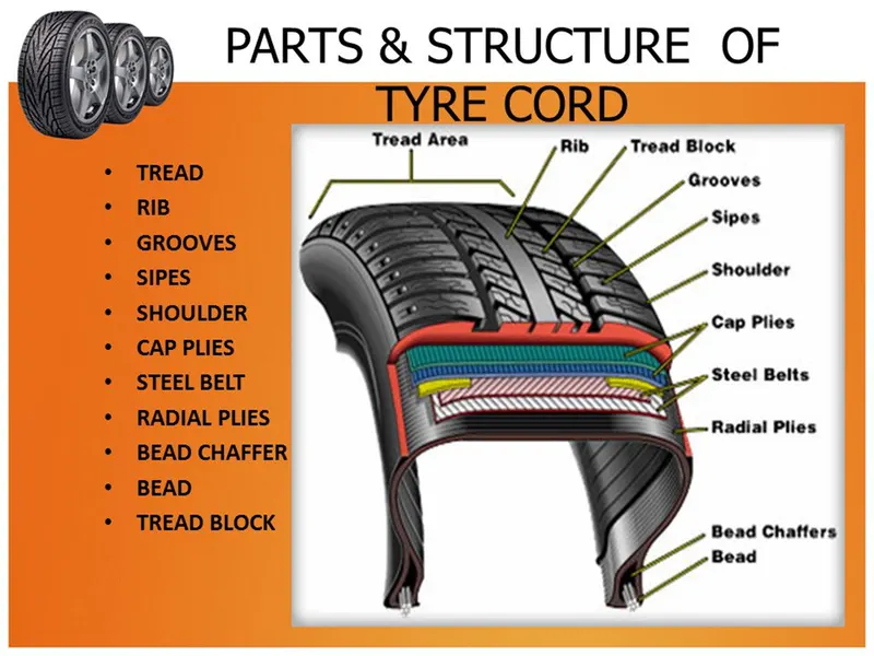
An aircraft tyre is designed to withstand extremely heavy loads while landing, take off, taxing, and parking. The number of wheels required for aircraft increases with the weight of the aircraft, as the weight of the aeroplane needs to be distributed more evenly.
Design and Construction of Aircraft tyre
Carcass plies are used to form the tire. They are sometimes called casing plies. An aircraft tyre is constructed for the purpose it serves.
- They support the weight of an aircraft while it is on the ground.
- It also provides the necessary traction for braking and stopping of an aeroplane.
- Tyre also helps to absorb the shock of landing and provide cushioning the roughness of takeoff, roll-out, and taxi operations.
Unlike an automobile or truck tyre, it does not have to carry a load for a long period of continuous operation. However, an aircraft tyre absorbs the high impact loads of landing, and also it’s operating at high speeds for a short time when required.
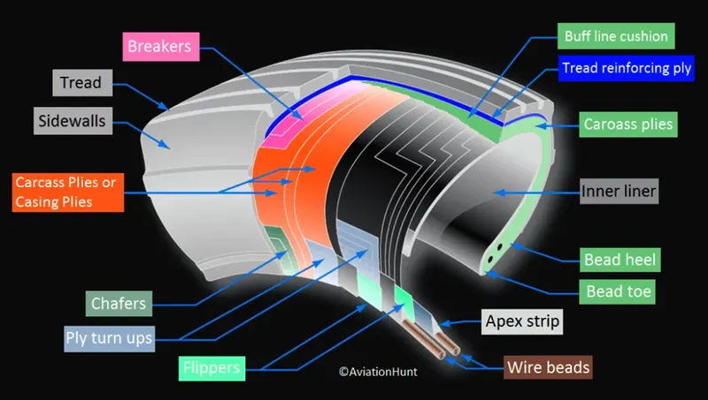
Retreading – Retreading is methods of restoring a worn tyre by renewing the tread area or by renewing the tread area plus one or both sidewalls. Repairs are included in the tyre retreading process.
Load Rating – Load rating is the maximum permissible load at a specified inflation pressure
Ply Rating – Ply Rating is used to identify the maximum recommended load rating and inflation pressure for a specified tyre. It is an index of tyre strength.
Speed Rating – The speed rating is the maximum takeoff speed to which the tyre has been tested.
Skid Depth – Skid depth is the distance between the tread surface and the deepest groove as measured in the mould.
Aircraft tyres must have an approved speed and load rating and have sufficient clearance when retracted through landing gear to allow for tyre growth. Tyre growth is the increase in the size of the tyre due to centrifugal forces at high speed.
Rolling Resistance
For a rolling tire, deformation of the tire material occurs while entering the contact patch. The original (undeformed) conditions are restored when the deformed area leaves the contact patch again. This process involves energy losses, mainly due to hysteresis of the rubber material. These losses arise in the tread area, the belt, the carcass, and the sidewalls.
The force that resists the motion of a body rolling on a surface is called the rolling resistance or the rolling friction.
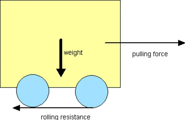
The rolling resistance can be expressed by the generic equation
Fr = c W (1)
where
Fr = rolling resistance or rolling friction (N, lbf)
c = rolling resistance coefficient - dimensionless (coefficient of rolling friction - CRF)
W = m ag
= normal force - or weight of the body (N, lbf)
m = mass of body (kg, lb)
ag =acceleration due to gravity (9.81 m/s2)
Note that the rolling resistance coefficient - c - is influenced by different variables like wheel design, rolling surface, wheel dimensions and more.
The rolling resistance can alternatively be expressed as
Fr = cl W / r (2)
where
cl = rolling resistance coefficient - dimension length (coefficient of rolling friction) (mm, in)
r = radius of wheel (mm, in)
Rolling Friction Coefficients
Some typical rolling coefficients:
|
Rolling Resistance Coefficient |
|
|
|
c |
cl (mm) |
|
|
0.001 - 0.002 |
0.5 |
railroad steel wheels on steel rails |
|
0.001 |
bicycle tire on wooden track |
|
|
0.002 - 0.005 |
low resistance tubeless tires |
|
|
0.002 |
bicycle tire on concrete |
|
|
0.004 |
bicycle tire on asphalt road |
|
|
0.005 |
dirty tram rails |
|
|
0.006 - 0.01 |
truck tire on asphalt |
|
|
0.008 |
bicycle tire on rough paved road |
|
|
0.01 - 0.015 |
ordinary car tires on concrete, new asphalt, cobbles small new |
|
|
0.02 |
car tires on tar or asphalt |
|
|
0.02 |
car tires on gravel - rolled new |
|
|
0.03 |
car tires on cobbles - large worn |
|
|
0.04 - 0.08 |
car tire on solid sand, gravel loose worn, soil medium hard |
|
|
0.2 - 0.4 |
car tire on loose sand |
|
Rolling Coefficients Cars
The rolling coefficients for air filled tires on dry roads can be estimated
c = 0.005 + (1 / p) (0.01 + 0.0095 (v / 100)2) (3)
where
c = rolling coefficient
p = tire pressure (bar)
v = velocity (km/h)
tyre pressure
Aircraft tires generally operate at high pressures, up to 200 psi (14 bar; 1,400 kPa) for airliners, and even higher for business jets. The main landing gear on the Concorde was typically inflated to 232 psi (16.0 bar), whilst its tail bumper gear tires were as high as 294 psi (20.3 bar)
In order to ensure that an aircraft’s tires are properly inflated, Michelin recommends checking the inflation pressure, with a calibrated gauge, before the first flight of the day or before each flight if not flown daily.
Why is it important to check the pressure every day?
Because of the high pressures and extreme temperatures at which aircraft tires operate, they do not hold air perfectly. In fact, an aircraft tire can lose up to 5 percent of its pressure in 24 hours and still be perfectly serviceable.
the tires of vehicle/car are dimensionally similar, they differ significantly in rated inflation pressure, load, and speed. Additionally, the passenger car and truck tires are able to operate continuously because they reach thermal equilibrium while aircraft tires do not. An aircraft tire which taxis continuously at rated load and 40 mph will continue to heat up until the tire fails. The failure to reach thermal equilibrium is a consequence of the high deflections (the difference between the unloaded and loaded tire section height) at which aircraft tires operate. High inflation pressure and high deflection rates – 2.5 times greater than a car tire – allow relatively small tires to support the high loads of an aircraft.
Because aircraft tires operate at such high extremes of pressure, load, and speed, their care and service is critically important. The most important action an operator can take to prevent tire-related events is to maintain proper tire inflation pressure. Failure to keep aircraft tires properly inflated can lead to very serious consequences. The most serious of these is the structural failure of the tire. If the tire operates underinflated or over deflected/overloaded, the nylon cords which form the structure of the tire go in and out of compression as the tire rotates. This weakens the cords – much like a paperclip which is bent back and forth – until eventually the cords break. If enough cords break, the entire structure will eventually fail. Figure 2 shows what a compressive break in an interior ply looks like. This particular break damaged the inner liner, allowing air to migrate through the tire to the atmosphere.
brake
in aircrafts the brake units are powered by the hydraulics system. An electrical signal is sent from the flight deck to hydraulic actuators near the main landing gear. Here, hydraulic fluid at 3,000 pound per square inch is used to force the brake unit against the wheel, thus slowing it down.
This system works fine, but the pipes and actuators that form this part of the hydraulic system come at a considerable weight cost. Extra weight means more fuel burn, which in turn increases costs and carbon emissions
here comes different types of brakes
ELECTRIC BRAKE
The brake system on the 787 Dreamliner is controlled by the pilots pressing the tops of the rudder pedals under their feet, demanding the rate of braking which they require. This sends an electronic signal to the Left and Right Brake System Control Units (BSCUs).
These then send signals to the four Electronic Brake Actuator Controllers (EBAC) which control the rate of braking on the wheels. Each wheel has four Electric Brake Actuators (EBA), a kind of piston which presses against the carbon brake discs
Anti-skid protection
When landing on slippery runways, there’s a chance that the wheels may start to skid as the brakes are applied. To stop this from happening and to maintain maximum effective braking, each wheel has anti-skid protection.
Using a variety of sources to determine the aircraft speed, the brake units know how fast the wheels should be spinning. If that speed drops significantly, it’s because the current brake pressure on that wheel is too great and the wheel is just skidding over the surface.
In this situation, the anti-skid system automatically reduces the braking on that wheel to a point where the skid stops before reapplying the pressure. All this is done in a fraction of a second
Autobrake
Pressing on the brakes is pretty straight forward when taxiing in a straight line at low speed. However, when we’re landing in strong winds, it can be a little tricky. We need to use our feet on the rudder pedals to line the nose of the aircraft up with the runway centerline at the last moment. Then, whilst holding that position, slide our feet up to press the toe brakes. Really not very easy when moving at 160 mph.
To help us get the braking underway as soon as we touch down, we have the autobrake system.This provides automatic braking at a preselected rate as soon as the aircraft senses that it is on the ground. It also provides full braking pressure in the case of a rejected takeoff if the speed is above 85 knots (98 mph).
MODULE2#
6.
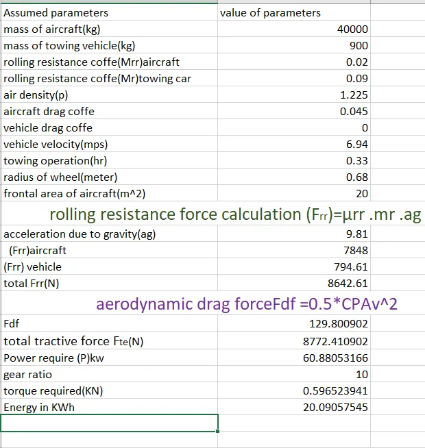
With necessary assumptions, calculate the force and power required to push / pull an aircraft by a towing vehicle.
The force to move an airplane on an absolute flat runway with no wind at constant low speed is equal to the rolling resistance between the plane and the tarmac.
also if aerodynamic drag is considered then the force that is required to move the aircraft at low speed will be equal to
here we are going to neglect the effect of aerodynamic drag
The rolling resistance for the air plane can be calculated as
Fr = μrr .mr .ag
where
Fr = rolling resistance (N, lbf)
μrr= rolling resistance coefficient
mr = rolling mass (kg, lbm)
ag = acceleration of gravity (9.81 m/s2)
Example - Force required to pull an airplane at constant low speed on tarmac
If the mass of a plane is 40000 kg and the rolling coefficient between the aircraft wheel and the tarmac is 0.02 - the force required to overcome the rolling resistance can be calculated as
Rolling Resistance force for air craft
Fr=μrr .mr .ag
Fr = 0.02 (40000 kg) (9.81 m/s2)
= 7848 N
This force can be delivered by a pulling truck to move the aircraft. Enough weight for the tow vehicle is required to create friction forces against the tarmac that equals the plane rolling resistance.
The friction force for the Tow vehicle can be calculated to
Fr=μrr .mr .ag
where
Ff = frictional force (N, lb)
mft = friction mass (kg)/mass of tow vehicle
Example - Required Mass for Pulling Truck
The friction coefficient between a pulling truck rubber wheels and dry tarmac is 0.9. Since pulling trucks are connected to air crafts nose wheels (a landing wheel under the nose of an aircraft) close to tarmac we simplify the calculation of required truck mass to
mf = (7848 N) / (0.9 (9.81 m/s2))
= 889 kg
therefor the mass of Tow vehicle that is required to move the air craft =889 or 900kg
Rolling resistance force for towing /push back truck can be calculated below
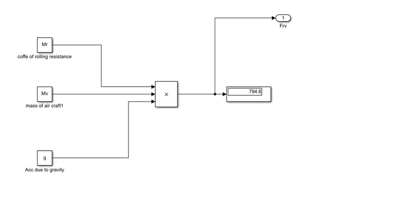
Frv=μr .mr .ag
Frv= frictional force for towing/pushback vehicle
mf =900kg
μrr=cofficient of rolling resistance=0.09 for tarmac and towing tire
therefore
Frv =0.09*900*9.8
=793.8N
so how much power is required to ovwercome the two rolling resistance force
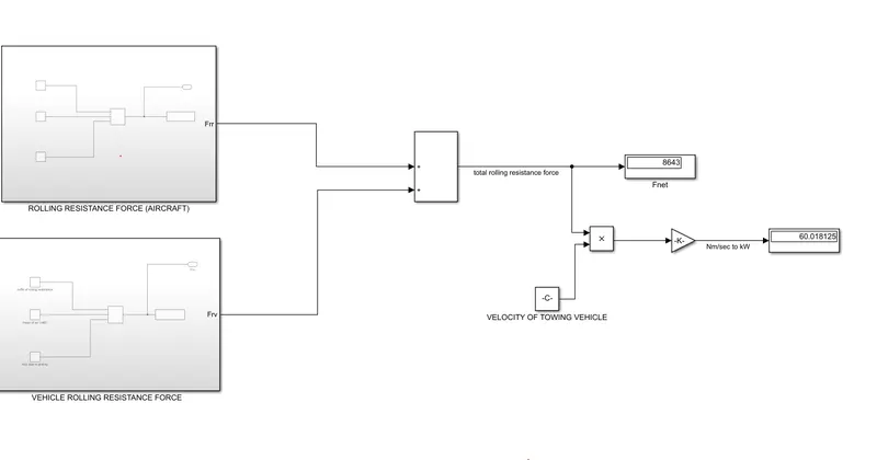
total resistance(Tractive force) Fte=Frr +Frv
=793.8N+7848 N
=8641.8N
Let v=25km/h=25*(5/18)=6.94m/s
therefore power required by towing vehicle to move the aircraft
P=Ft*V
P= 8641.8*6.94 (Nm/sec)
1Nm/s=1kw
P=59.97KW
how much torque is required
Fte=T*G/r
where Fte=total tractive force (rolling resistance force+aerodynamic force+hill climbing force)
r=radius of the towing wheel
T=torque
considering heavey duty vehicle
gear ratio G=10
radius of the wheel(r)=27inch.......1 inch=25.4mm=0.0254m
=0.6858m
Fte=T*G/r
8641.8N=T*10/0.6858
T=592.65Nm=0.592KNm
therefore Torque required to pull or push the aircraft =0.592kN
hence we have to devlop motor that will give the required power and torque considering the above case if aerodynamice drag/force is considered then power and torque requirement will vary accordingly.from the above case we have neglected the the aerodynamic drag and considered only vehicle and aircraft rolling ressistance force also we have neglected the hillclimbing force as the airport rauway we have considered flate.
the power and torque that is require to develop a motor to full fill the above condtions
power=59.97KW
Torque=0.592kNm
Develop the model for the calculated force and power using Simulink
equations that we are going to use in simulink model
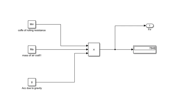
in ther above case we have only consider rolling resistance force and the effect of aerodynamic drag has been neglected
Rolling resistance force (aircraft)
Frr=μrr .mr .ag
Rolling resistance force(towing vehicle)
Fr=μr .mr .ag
A. Design an electric powertrain with type of motor, it’s power rating, and energy requirement to fulfill aircraft towing application in Simulink. Estimate the duty cycle range to control the aircraft speed from zero to highest. Make all required assumptions. Prepare a table of assumed parameters. Draw a block diagram of powertrain.
Design of electric powertrain /electric motor for towing vehicle
points to be noted while designing electric motors
how much energy is required that a motor will deliver
from the above case our power requirement =59.97KW
and requirement of torque=0.59KNm
as we know that energy is the capacity to do work therefore we can say that the towing vehicle battery must be able to store the energy and posses to deliver enough energy while operating
Energy=Power*time of operation(hr)
let the towing vehicle is operating for 20 minutes
therefore energy required to be delivered by the towing vehicle E=59.97(KW)*(20/60hr)
E=19.99KWh
therefore the battery must be store the energy of 19.99KWh and should ab able to deliver the energy throughout the run time and also to produce torque of 0.59KNm
motor spececification
power conveters
we are going to use DC DC boost conveter
dc dc boost conveter is used to upscale the voltage level from the battery to required level
The dc–dc converters are implemented by the use of semiconductors, like (IGBTs), power(MOSFETs), thyristors, or another power-controlled semiconductor device as well as diodes and LC circuits. At this point should be noted that the above gate controlled semiconductors operate as switches. These controlled semiconductor devices are operating only in the conduction state or in the blocking state. If a gating pulse is applied to the gate of an IGBT or MOSFET, then they will be switched into the conduction mode and will remain in this state until the end of the gating pulse interval. When the gating pulse becomes zero, the semiconductor devices are switched into blocking mode. This is the reason they are called semiconductor switches,
speed control of electric vehicle
The electric vehicle controller is the electronics package that operates between the batteries and the motor to control the electric vehicle‘s speed and acceleration much like a carburetor does in a gasoline-powered vehicle. The controller transforms the battery’s direct current into alternating current (for AC motors only) and regulates the energy flow from the battery. Unlike the carburetor, the controller will also reverse the motor rotation (so the vehicle can go in reverse), and convert the motor to a generator (so that the kinetic energy of motion can be used to recharge the battery when the brake is applied).
In the early electric vehicles with DC motors, a simple variable-resistor-type controller controlled the acceleration and speed of the vehicle. With this type of controller, full current and power was drawn from the battery all of the time. At slow speeds, when full power was not needed, a high resistance was used to reduce the current to the motor. With this type of system, a large percentage of the energy from the battery was wasted as an energy loss in the resistor. The only time that all of the available power was used was at high speeds.
Modern controllers adjust speed and acceleration by an electronic process called pulse width modulation. Switching devices For more information, visit avt.inl.gov such as silicone-controlled rectifiers rapidly interrupt (turn on and turn off) the electricity flow to the motor. High power (high speed and/or acceleration) is achieved when the intervals (when the current is turned off) are short. Low power (low speed and/or acceleration) occurs when the intervals are longer. The controllers on most vehicles also have a system for regenerative braking. Regenerative braking is a process by which the motor is used as a generator to recharge the batteries when the vehicle is slowing down. During regenerative braking, some of the kinetic energy normally absorbed by the brakes and turned into heat is converted to electricity by the motor/controller and is used to re-charge the batteries. Regenerative braking not only increases the range of an electric vehicle by 5 - 10%, it also decreases brake wear and reduces maintenance cost.
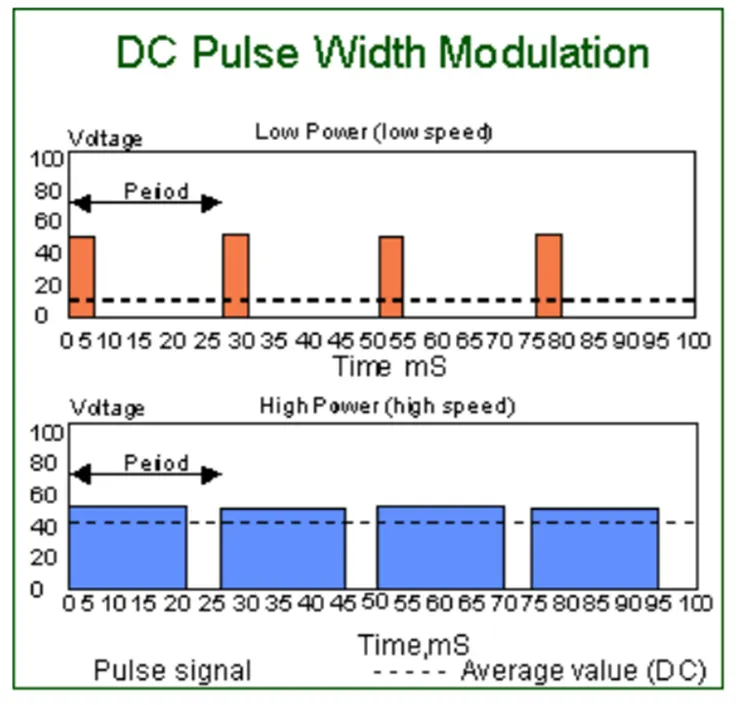
since the armature voltage =380v the boost conveter converts it to high voltage to 900 v
therefore
the output power can be controled by implementing duty cycle
therefore motor terminal voltage=duty cycle*armature voltage
let duty cycle =80%
=0.8*900
motor terminal voltage=720
therefore with duty cycle 80% the voltage at moter terminal=720v
thus by varying the duty cycle we camn controle speed of the motor which in turn controls the the speed of the vehicle.
Design the parameters in excel sheet.