Project-1: Powertrain for aircraft in runways
Aim
Part A:
1. Search and list out the total weight of various types of aircrafts.
MTOW = Maximum take-off weight, MLW = Maximum landing weight, TOR = Take-off run (SL, ISA+15°, MTOW), LR = Landing run (SL, ISA+15°, MLW)
| Type | MTOW [kg] | MLW [tonnes] | TOR [m] | LR [m] | ICAO category | FAA category |
|---|---|---|---|---|---|---|
| Antonov An-225 | 640,000 | 591.7 | 3500 | Heavy | Super | |
| Scaled Composites Model 351 Stratolaunch | 589,670 | 3660 | Heavy | Super | ||
| Airbus A380-800[1][2][3] | 575,000 | 394 | 3100 | 1930 | Super | Super |
| Boeing 747-8F | 447,700 | 346.091 | 3100 | 1800 | Heavy | Heavy |
| Boeing 747-8 | 443,613 | 306.175 | 3100 | Heavy | Heavy | |
| Boeing 747-400ER | 412,770 | 295.742 | 3090 | Heavy | Heavy | |
| Antonov An-124-100M | 405,060 | 330 | 2520 | 900 | Heavy | Heavy |
| Boeing 747-400 | 396,900 | 295.742 | 3018 | 2179 | Heavy | Heavy |
| Lockheed C-5 Galaxy[4][5][6] | 381,000 | 288.417 | 2530 | 1494 | Heavy | Heavy |
| Boeing 747-200[7] | 377,840 | 285.700 | 3338 | 2109 | Heavy | Heavy |
| Boeing 747-300[7] | 377,840 | 260.320 | 3222 | 1905 | Heavy | Heavy |
| Airbus A340-500[8] | 371,950 | 240 | 3050 | 2010 | Heavy | Heavy |
| Airbus A340-600[8] | 367,400 | 256 | 3100 | 2100 | Heavy | Heavy |
| Boeing 777F | 347,800 | 260.816 | 2830 | Heavy | Heavy | |
| Boeing 777-300ER | 351,800 | 251.29 | 3100 | Heavy | Heavy | |
| Boeing 777-200LR | 347,450 | 223.168 | 3000 | Heavy | Heavy | |
| Boeing 747-100[7] | 340,200 | 265.300 | Heavy | Heavy | ||
| Airbus A350-1000 | 308,000 | 233.5 | Heavy | Heavy | ||
| Boeing 777-300 | 299,370 | 237.683 | 3380 | Heavy | Heavy | |
| Boeing 777-200ER | 297,550 | 213.00 | 3380 | 1550 | Heavy | Heavy |
| Airbus A340-300[8][9] | 276,700 | 190 | 3000 | 1926 | Heavy | Heavy |
| McDonnell Douglas MD-11 | 273,300 | 185 | 2990 | 1890 | Heavy | Heavy |
| Airbus A350-900 | 270,000 | 175 | 2670 | 1860 | Heavy | Heavy |
| Ilyushin Il-96M | 270,000 | 195.04 | 3115 | 2118 | Heavy | Heavy |
| McDonnell Douglas DC-10 | 256,280 | 183 | 2990 | 1890 | Heavy | Heavy |
| Boeing 787-9[10] | 254,000 | 192.777 | 2900 | Heavy | Heavy | |
| Boeing 787-10[10] | 254,000 | 201.849 | Heavy | Heavy | ||
| Airbus A340-200[8][11] | 253,500 | 181 | 2990 | Heavy | Heavy | |
| Airbus A330-900 | 251,000 | 191 | 3100 | Heavy | Heavy | |
| Ilyushin IL-96-300 | 250,000 | 175 | 2600 | 1980 | Heavy | Heavy |
| Airbus A330-300[12][13] | 242,000 | 185 | 2500 | 1750 | Heavy | Heavy |
| Airbus A330-200[12][13] | 242,000 | 180 | 2220 | 1750 | Heavy | Heavy |
| Lockheed L-1011-500 | 231,300 | 166.92 | 2636 | Heavy | Heavy | |
| Boeing 787-8[10] | 228,000 | 172.365 | 3300 | 1695 | Heavy | Heavy |
| Lockheed L-1011-200 | 211,400 | Heavy | Heavy | |||
| Ilyushin IL-86 | 208,000 | 175 | Heavy | Heavy | ||
| Boeing 767-400ER | 204,000 | 158.758 | 3414 | Heavy | Heavy | |
| Airbus A300-600R[14] | 192,000 | 140 | 2385 | 1555 | Heavy | Heavy |
| Boeing 767-300ER | 187,000 | 136.08 | 2713 | 1676 | Heavy | Heavy |
| Concorde | 185,000 | 111.1 | 3440 | 2220 | Heavy | Heavy |
| Airbus A300-600[14] | 163,000 | 138 | 2324 | 1536 | Heavy | Heavy |
| Boeing 767-300 | 159,000 | 136.078 | 2713 | 1676 | Heavy | Heavy |
| Airbus A310-300[14] | 157,000 | 124 | 2290 | 1490 | Heavy | Heavy |
| Vickers VC10 | 152,000 | 151.9 | Heavy | Heavy | ||
| Boeing 707-320B[15] | 151,000 | 97.5 | Heavy | Heavy | ||
| Boeing 707-320C[15] | 151,000 | 112.1 | Heavy | Heavy | ||
| Douglas DC-8-61 | 147,000 | Heavy | Heavy | |||
| Airbus A310-200[14] | 142,000 | 123 | 1860 | 1480 | Heavy | Heavy |
| Airbus A400M | 141,000 | 122 | 980 | 770 | Heavy | Heavy |
| Douglas DC-8-32 | 140,000 | Heavy | Heavy | |||
| Douglas DC-8-51 | 125,000 | Medium | Large | |||
| Boeing 757-300 | 124,000 | 101.6 | 2550 | 1750 | Medium | Large |
| Boeing 707-120B[15] | 117,000 | 86.3 | Medium | Large | ||
| Boeing 757-200 | 116,000 | 89.9 | 2347 | 1555 | Medium | Large |
| Boeing 720B[16] | 106,000 | 79.5 | Medium | Large | ||
| Boeing 720[16] | 104,000 | 79.5 | Medium | Large | ||
| Tupolev Tu-154M | 104,000 | 80 | Medium | Large | ||
| Tupolev Tu-204SM | 104,000 | 87.5 | 2250 | Medium | Large | |
| Convair 880 | 87,500 | Medium | Large | |||
| Boeing 737-900 | 85,000 | 66.36 | 2500 | 1704 | Medium | Large |
| Boeing 737-900ER | 85,000 | 71.35 | 2804 | 1829 | Medium | Large |
| Boeing 727-200 Advanced[17] | 84,000 | 70.1 | Medium | Large | ||
| Airbus A321-100[18] | 83,000 | 77.8 | 2200 | 1540 | Medium | Large |
| Boeing 737-800 | 79,000 | 65.32 | 2308 | 1634 | Medium | Large |
| Boeing 727-200[17] | 78,000 | 68.1 | Medium | Large | ||
| McDonnell-Douglas MD-83 | 73,000 | 63.28 | Medium | Large | ||
| Boeing 727-100[17] | 72,500 | 62.4 | Medium | Large | ||
| Boeing 727-100C[17] | 72,500 | 62.4 | Medium | Large | ||
| McDonnell-Douglas MD-90-30 | 71,000 | 64.41 | 2165 | 1520 | Medium | Large |
| de Havilland Comet 4 | 70,700 | Medium | Large | |||
| Boeing 737-700 | 70,000 | 58.06 | 1921 | 1415 | Medium | Large |
| Airbus A320-100[18] | 68,000 | 66 | 1955 | 1490 | Medium | Large |
| Boeing 737-400 | 68,000 | 54.9 | 2540 | 1540 | Medium | Large |
| de Havilland Comet 3 | 68,000 | Medium | Large | |||
| Boeing 377 | 67,000 | Medium | Large | |||
| Boeing 737-600 | 66,000 | 54.66 | 1796 | 1340 | Medium | Large |
| Airbus A220-300 | 65,000 | 57.61 | 1890 | 1494 | Medium | Large |
| Hawker Siddeley Trident 2E | 65,000 | Medium | Large | |||
| Airbus A319[18] | 64,000 | 62.5 | 1850 | 1470 | Medium | Large |
| Boeing 737-300 | 63,000 | 51.7 | 1939 | 1396 | Medium | Large |
| Boeing 737-500 | 60,000 | 49.9 | 1832 | 1360 | Medium | Large |
| Airbus A220-100 | 59,000 | 50.80 | 1463 | 1356 | Medium | Large |
| Airbus A318[18] | 59,000 | 57.5 | 1375 | 1340 | Medium | Large |
| Boeing 717-200HGW | 55,000 | 47.174 | 1950 | Medium | Large | |
| Douglas DC-7 | 55,000 | Medium | Large | |||
| de Havilland Comet 2 | 54,000 | Medium | Large | |||
| Boeing 717-200BGW | 50,000 | 46.265 | 1950 | Medium | Large | |
| de Havilland Comet 1 | 50,000 | Medium | Large | |||
| Douglas DC-6A | 48,600 | Medium | Large | |||
| Douglas DC-6B | 48,500 | Medium | Large | |||
| Embraer 190[19] | 48,000 | 43 | 2056 | 1323 | Medium | Large |
| Caravelle III | 46,000 | Medium | Large | |||
| Fokker 100 | 46,000 | 39.95 | 1621 | 1350 | Medium | Large |
| Douglas DC-6 | 44,000 | Medium | Large | |||
| Avro RJ-85 | 42,000 | 36.74 | Medium | Large | ||
| Handley Page Hermes | 39,000 | Medium | Large | |||
| Embraer 175[20] | 37,500 | 32.8 | 2244 | 1304 | Medium | Large |
| Bombardier CRJ900[21] | 36,500 | 33.345 | 1778 | 1596 | Medium | Large |
| Embraer 170[22] | 36,000 | 32.8 | 1644 | 1274 | Medium | Large |
| Bombardier CRJ700 | 33,000 | 30.39 | 1564 | 1478 | Medium | Large |
| Douglas DC-4 | 33,000 | Medium | Large | |||
| Vickers Viscount 800 | 30,400 | Medium | Large | |||
| Bombardier Q400 | 28,000 | 28.01 | 1219 | 1295 | Medium | Large |
| Bombardier CRJ200 | 23,000 | 21.319 | 1918 | 1479 | Medium | Large |
| ATR 72-600 | 22,800 | 22.35 | 1333 | 914 | Medium | Large |
| Saab 2000 | 22,800 | 21.5 | 1300 | Medium | Large | |
| Embraer ERJ 145 | 22,000 | 19.3 | 2270 | 1380 | Medium | Large |
| ATR 42-500 | 18,600 | 18.3 | 1165 | 1126 | Medium | Small |
| Saab 340 | 13,150 | 12.930 | 1300 | 1030 | Medium | Small |
| Embraer 120 Brasilia | 11,500 | 11.25 | 1560 | 1380 | Medium | Small |
| BAe Jetstream 41 | 10,890 | 10.570 | 1493 | 826 | Medium | Small |
| Learjet 75[23] | 9,752 | 8.709 | 1353 | 811 | Medium | Small |
| Pilatus PC-24[24] | 8,300 | 7.665 | 893 | 724 | Medium | Small |
| Embraer Phenom 300[25] | 8,150 | 7.65 | 956 | 677 | Medium | Small |
| Beechcraft 1900D | 7,765 | 7.605 | 1036 | 853 | Medium | Small |
| Cessna Citation CJ4[26] | 7,761 | 7.103 | 1039 | 896 | Medium | Small |
| de Havilland Hercules | 7,000 | Medium | Small | |||
| Embraer Phenom 100 | 4,800 | 4.43 | 975 | 741 | Light | Small |
2. Is there any difference between ground speed and air speed?
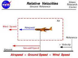
Ground Speed
For a reference point picked on the ground, the aircraft moves relative to the reference point at the ground speed. Ground speed is also a vector quantity so a comparison of the ground speed to the wind speed must be done according to rules for vector comparisons.
Airspeed
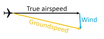
The important quantity in the generation of lift is the relative velocity between the object and the air, which is called the airspeed. Airspeed cannot be directly measured from a ground position, but must be computed from the ground speed and the wind speed. Airspeed is the vector difference between the ground speed and the wind speed.
Airspeed = Ground Speed - Wind Speed
3. Why is it not recommended to use aircraft engine power to move it on the ground at Airport?
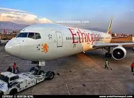
Commercial aircrafts are equipped with engines rated from 18,000 to nearly 100,000 lbs of thrust. Such thrust levels provide for safe takeoff, flight, and landing over a wide range of temperatures, altitudes, gross weights, and payload conditions. However, the exhaust wake from these engines can pose hazards in commercial airport environments. Operators and airport authorities must carefully consider these hazards and the resulting potential for injury to people and damage to or caused by baggage carts, service vehicles, airport infrastructure, and other airplanes.
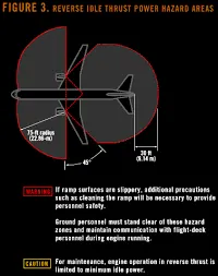
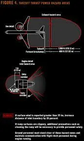
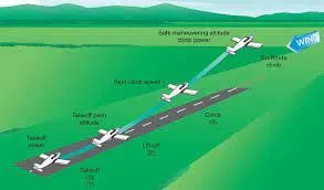
When modern jet engines are operated at rated thrust levels, the exhaust wake can exceed 603 Km/hr from the engine exhaust nozzle. This exhaust flow field extends in a rapidly expanding cone, with portions of the flow field contacting and extending along the pavement surface as shown in the figure above. Exhaust velocity components are attenuated with increasing distance from the engine exhaust nozzle. However, an airflow of 483 km/h can still be present at the empennage, and significant people and equipment hazards will persist hundreds of feet beyond this area. At full power, the exhaust wake speed can typically be 240 km/h at 200 ft beyond the airplane and 80 to 161 km/h well beyond this point.
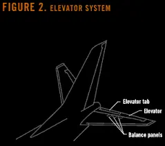
If the power from the engine's aircraft is high when on the ground, the thrust produced can lead to Foreign Object Damage or FOD which can damage the aircraft's structure and/or equipments and personnel. Debris from the ground wether on the taxiway or runway can get sucked into the engine and can not only damage the components inside the engine but also the stabilizers, elevators or fuselage.
Thrust from the engine can also blow any ground equipment away if in case they are not fastened and can also harm ground personnel either from the suction force of the engine blades or from the exhaust wake or due to flying debris or equipment hitting them. The figure above shows the hazardous zones of an engine when the aircraft is on the ground and this can also include the thrust required for taxiing.
Therefore due to the high thrust produced by the engine, it is not recommended to use the engine's power when it is on the ground if it is stationary or taxiing due to the exahust wake and the force produced by the intake blades.
4. How an aircraft is pushed to runway when its ready to take off?
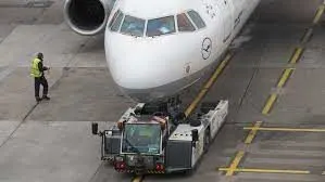
The process of pushing an aircraft to the runway when its ready to take-off is called as Pushback. It is an airport procedure during which an aircraft is pushed backwards away from an airport gate towards the runway by external power. Pushbacks are carried out by special, low-profile vehicles called pushback tractors or tugs.
Although many aircraft are capable Of moving themselves backwards on the ground using reverse thrust (a procedure referred to as a powerback), the resulting jet blast or prop wash might cause damage to the terminal building or equipment. Engines close to the ground may also blow sand and debris forward and then suck them into the engine, causing damage to the engine. A pushback is therefore the preferred method to move the aircraft away from the gate
Pushbacks at busy aerodromes are usually subject to ground control clearance to facilitate ground movement on taxiways. Once clearance is obtained, the pilot will communicate with the tractor driver (or a ground handler walking alongside the aircraft in some cases) to start the pushback. To communicate, a headset may be connected near the nose gear.
Since the pilots cannot see what is behind the aircraft, steering is done by the pushback tractor driver and not by the pilots. Depending on the aircraft type and airline procedure, a bypass pin may be temporarily installed into the nose gear to disconnect it from the aircraft's normal steering mechanism.
5. Learn about take off power, tyre design, rolling resistance, tyre pressure, brake forces when landing.
take off power :
The amount of power that an engine is allowed to produce for a limited period of time for takeoff. The use of takeoff power is usually limited to 5 min for reciprocating engines and up to 2h min for gas turbine engines. This may not always be the case. Specifically, with respect to reciprocating engines, it is the brake horsepower developed under standard, sea-level conditions and under the maximum conditions of the crankshaft rotational speed and the engine manifold pressure approved for the normal take-off. It is limited in continuous use to the period of time shown in the approved engine specifications. With respect to gas turbine engines, it is the thrust developed under static conditions at a specified altitude and atmospheric conditions of the rotor shaft rotational speed and gas temperature approved for the normal takeoff. It is limited in continuous use to the period of time shown in the approved engine specifications
tyre design:
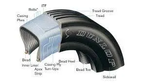
-An aircraft tyre are deisgned to withstand extreme heavy loads by absording shocks during and there by providing cushioning effect.
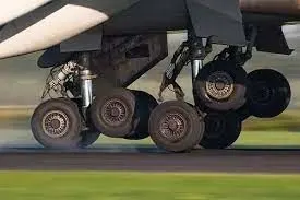
-The number of tires required for an aircraft depends on the total weight of aircraft as the weight needs to be distributed evenly.
-Aircratt tyre are designed to tacillitate stability in high crosswind condition,to chanalize the water away tor preventing skidding and helps to give a good braking effect.
-Aircraft tires are usually inflated by nitrogen air inorder to reduce expansion and contraction from extrerme changes in ambient pressure and tempurature.This type of inert gases will eliminate the possibilty of tire explosion.
-Aircraft tire design are set into an aircraft based on its application and also suffeicient clearance with the ground for allowing tyre growth which happens when centrifugal force is at high speed.
rolling resistance:
Tire rolling resistance is the energy that your vehicle needs to send to your tyres to maintain movement at a constant speed over the surface. In other words, it is the effort required to keep a tyre rolling. It is mainly caused by non-elastic effects; i.e not all the energy needed for deformation (or movement) of the wheel, roadbed, etc. is recovered when the pressure is removed. The main contributor to the Rolling Resistance is the process known as Hysteresis. Hysteresis is essentially the energy loss that occurs as a tire rolls through its footprint. The energy loss must be overcome by the vehicle's engine which results in wasted fuel.
The Rolling Resistance can be expressed by the generic equation:
Fr=c *m •g where; c is the rolling resistance coeficient(dimensionless) m is the mass of the body(kg or 1b) g is the acceleration of gravity(9.8m/sec2 or 32.174ft/sec2)
The Rolling Resistance Coefficient is greatly get influenced by the factors like wheel design, rolling surface, wheel dimensions, etc.
Some typical values of rolling resistance coefficient(c )for different vehicles is shown in the figure given below:
|
Rolling Resistance Goemclent |
||
|
c, (mm) |
||
|
0.001 - 0.002 |
0.5 |
railroad steel wheels on steel rails |
|
0.001 |
bicycle tire on wooden track low resistance tubeless tires bicycle lire on concrete bicycle tire on asphalt road |
|
|
0.002 - 0.005 |
||
|
0.002 |
||
|
0.004 |
||
|
0.005 |
dirty tram rails |
|
|
- 0.01 |
truck tire an asphalt |
|
|
0.008 |
bicycle tire on rough paved road |
|
|
0.01 - 0.015 |
ordinary car tires on concrete, new asphalt, coööles small new car tires on tar or asphalt car tires on gravel - rolled new car tires on coööles - large worn |
|
|
o. 02 |
||
|
o. 02 |
||
|
o. 03 |
||
|
0.04 - 0.08 |
car tire on solid sand, gravel loose worn, soil medium nard |
|
|
car tire on loose sand |
||
Part B:
6. A. With necessary assumptions, calculate the force and power required to push / pull an aircraft by a towing vehicle.
The forces acting on an aircraft during the push and pull of the towing vehicle are Rolling Resistance, Air drag force.
Assumptions:
Let us assume an Aircraft of Antonov An-225 plane.
Mass of the Aircraft 'ml' = 247000 kg,
Mass of the Towing Vehicle m2 = 50000kg,
Coefficient of Rolling ground friction for Dry concrete or asphalt road 0.03,
Frontal Area of the Vehicle 35m A2,
Drag coefficient of an aircraft 0.6,
Drag coefficient of an Towing Vehicle Cd(Towing)= 0.15,
Density of air = 1.225 kgm A3,
Gravity g = 9.81msA2,
Speed of an aircraft = 20kmph = 20*5/18= 5.556 m/sec,
Rolling Resistance Force:
For the Aircraft:
Frraircraft=rrxmxg
Frraircraft=O.03x247000x9.81
Frraircraft=72692.1 N
For the Towing Vehicle:
We need to add the mass of the Aircraft as the Towing Vehicle is pushing/ pulling the aircraft as well therefore, the total rolling resistance force will be:
Total Rolling Resistance force
Frr=Frraircraft+Frr(vehicIe)
Err-72692.1+14715
Frr=87407.1 N
Aerodynamic Drag force:
Fad=12xpxAxv2x(Cd(Aircraft)+Cd(Towing))
Fad=4750.47N
Total Force of the Towing Vehicle,
F=Fad+Frr(vehicle)
F=4750.47+87407.l
F-92157.57 N Power Required, 92157.57x5.556
512.027 KW
The Force and Power of the Towing vehicle carrying the Aircraft are 92.157KN and 512.027 KN.
B. Develop the model for the calculated force and power using Simulink.
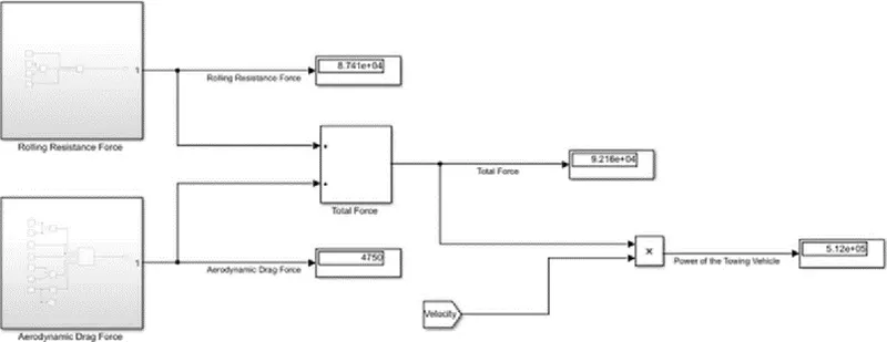
7. A. Design an electric powertrain with type of motor, it’s power rating, and energy requirement to fulfill aircraft towing application in Simulink. Estimate the duty cycle range to control the aircraft speed from zero to highest. Make all required assumptions. Prepare a table of assumed parameters. Draw a block diagram of powertrain.
(Hint :DC7 Block)
B. Also, Design the parameters in excel sheet.
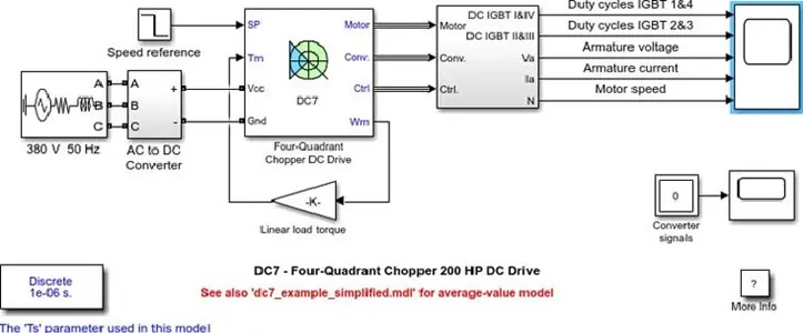
DESCRIPTION:
The 200 HP DC motor is separately excited with a constant 150 V DC field voltage source. The armature voltage is provided by an IGBT converter controlled by two PI regulators. The converter is fed by a 515 V DC bus obtained by rectification Of a 380 V AC 50 Hz voltage source. In order to limit the DC bus voltage during dynamic braking mode, a braking chopper has been added between the diode rectifier and the DC7 block.
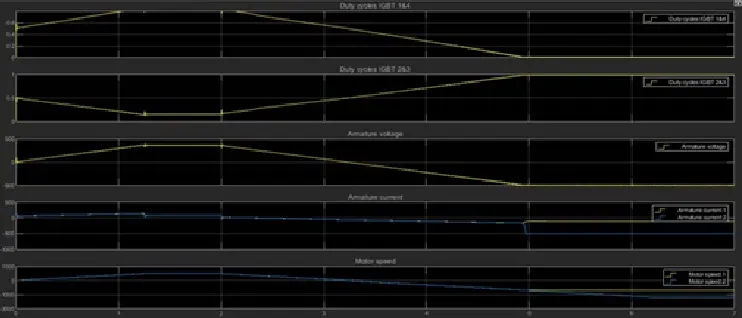
The first regulator is a speed regulator, followed by a current regulator. The speed regulator outputs the armature current reference (in p.u.) used by the current controller in order to obtain the electromagnetic torque needed to reach the desired speed The speed reference change rate follows acceleration and deceleration ramps in order to avoid sudden reference changes that could cause armature over-current and destabilize the system. The current regulator controls the armature current by computing the appropriate duty ratios of the 5 kHz pulses of the four IGBT devices (Pulse Width Modulation). For proper system behaviour, the instantaneous pulse values of IGBT devices 1 and 4 are opposite to those of IGBT devices 2 and 3. This generates the average armature voltage needed to obtain the desired armature current. In order to limit the amplitude of the current oscillations, a smoothing inductance is placed in series with the armature circuit.
OUTPUT:
SIMULATION:
Before starting the simulation, set the initial bus voltage to 515 V via the GUI block ('Initial States Setting' button and 'Cbus' variable).
Start the simulation. You can observe the motor armature voltage and current, the four IGBT pulses and the motor speed on the scope The current and speed references are also shown.
The motor is coupled to a linear load, which means that the mechanical torque of the load is proportional to the speed
The speed reference is set at 500 rpm at t O s. Observe that the motor speed follows the reference ramp accurately (+400 rpm/s) and reaches steady state around t = 1.3 s.
The armature current follows the current reference very well, with fast response time and small ripples Notice that the current ripple frequency is 5 kHz.
At t = 2 s, speed reference drops to -1184 rpm. The Current reference decreases to reduce the electromagnetic torque and causes the motor to decelerate with the help of the load torque.
At t = 2.2 s, the current reverses in order to produce a braking electromagnetic torque (dynamic braking mode). This causes the DC bus voltage to increase
At t = 3.25 s, the motor reaches O rpm and the load torque reverses and becomes negative. The negative current now produces an accelerating electromagnetic torque to allow the motor to follow the negative speed ramp (-400 rpm's). At t 6.3 s, the speed reaches -1184 rpm and stabilizes around its reference.
CONCLUSION:-
The parameters assumed for designing this vehicle is taken from online references
|
S.No. Assumed Parameters |
Assumed Values |
|
Weight of the Aircraft |
575000 kg |
|
2. Weight of the Towing Tractor |
50000 kg |
|
3. Rolling Resistance Coefficient of Aircraft |
0.004 |
|
4. Rolling Resistance Coefficient of Towing Tractor |
0.001 |
|
5. The velocity of the Aircraft while Towing |
8.33 m,'s |
|
6. Density of Air medium(rho) |
1.225 kg/mA3 |
|
7. The Frontal area of the Aircraft |
20 rrf2 |
|
8. The Coefficient of Drag of the Aircraft |
0.026 |
|
9. Towing Tractor Gear ratio(G- for high torque output) |
11 |
|
10. Towing Tractor tyre radius(r) |
0.635 m |
|
11. Operational time of the Towing for one cycle |
0.33 Hour |
|
12. The Battery Armature Voltage |
350 v |
|
13. The Battery Armature Current |
350 A |
|
14. The Motor Terminal Voltage for full power output |
630 V @ motor terminals |
|
15. Power converters used |
Bidirectional DC-DC Boost Converter |
|
16. The maximum duty ratio for acieving full power |
70% |
Assuming the operational time of the Towing Truck is around 20 minuts for one cycle
20 minutes - 0.33 hour
Energy(kwh) = power(kw)*Time(h) = 162.8*0.33
Energy(kwh) = 53.7 kWh
Therefore the battery must be able to store the energy 41.8 kWh and should deliver the energy throughout the run time in order for the motor to produce the 1.32 KNm of torque instantaneously. Thus the storage of energy in batteries with high performance Ultracapacitors are selected to fulfill the required power deliver.
Motor Selection:
Here we have selected a BLDC Motor type that has a power rating of 126.8kw and with the gear ratio and the transmission it should be able to deliver 1.32KNm of torque instantaneously.
|
The Battery Armature Voltage (V) |
350 v |
|
The Battery Armature Current (A) |
350 A |
Power Converter:
A boost converter (step-up converter) is a DC-to-DC power converter that steps up voltage (while stepping down current) from its input (supply) to its output (load). It is a class of sui.rched.:mQd.zuu.eL-supply (SMPS) containing at least two semiconductors (a and a and at least one energy storage element: a inductor, or the two in combination. To reduce filters made of capacitors (sometimes in combination with inductors) are normally added to such a converter's output (load-side filter) and input (supply-side filter).
Speed Control of the Vehicle:
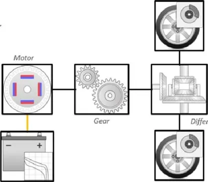
The Electric Vehicle uses power from the battery source to drive the motor and then further to drive the wheels in order to move the vehicle. The speed and torque generated from the motor is very important to drive the vehicle as per the driver's desire. If we connect the battery directly to the motor the motor will spin with a speed and torque characteristics which will be based on the full power of the battery voltage. We does not require full power in all the driving conditions so we need to adopt a power controller between the bettery and the motor so that the motor speed may be controlled by the driver to drive the vehicle as desired. For controlling the vehicle power we use the soft switching operation technique here. The amount of power can be controlled by changing the Duty Cycle value. Considering the losses we take 70% of the duty cycle to deliver the maximum power of the motor.
Motor Terminal Voltage = Armature Voltage * Duty Cycle = 900*0.7
With 70% Duty Cycle the voltage at motor terminals = 630V, Which gives the full power with all the gearings instantaneously. Thus by varying the Duty Cycle value the speed of the vehicle is controlled
Conclusion:
The reference Aircraft taken here is the Heavy Aircraft build and so our designed towing tractor is a heavy-duty operational vehicle. The power requirements are calculated for the particular load to be pushed/pulled and to achieve this power at the motor output, the motor type and its voltage at the terminals are discussed.
Then the power converters are used to upscale the battery armature voltage to the desired high voltage value so that the motor may sin at full newer and required torque can be achieved using a Bidirectional DC-DC Converter. Finally, the speed control of the vehicle is done we