Project-1: Powertrain for aircraft in runways
PART:A
AIM:
1. Search and list out the total weight of various types of aircrafts.
Typical Airplane Weights
Below is a table of some of the most common aircraft flying around our skies today:
| Aircraft | Empty Weight | Max Fuel Weight | Max Cargo Weight | Max Gross Takeoff Weight |
| Antanov AN-225 | 628,000 lbs | 661,400 lbs | 417,000 lbs | 1,411,000 lbs |
| 285,000 kg | 300,000 kg | 190,000 kg | 640,000 kg | |
| Airbus A380-800 | 611,000 lbs | 560,000 lbs | 185,000 lbs | 1,268,000 lbs |
| 277,000 kg | 254,000 kg | 84,000 kg | 575,000 kg | |
| Boeing 747-800 | 485,300 lbs | 427,400 lbs | 295,000 lbs | 987,000 lbs |
| 220,100 kg | 194,000 kg | 134,000 kg | 447,700 kg | |
| Airbus A340-500 | 370,000 lbs | 386,300 lbs | 119,000 lbs | 820,000 lbs |
| 168,000 kg | 175,000 kg | 54,000 kg | 372,000 kg | |
| Boeing 777-300ER | 370,000 lbs 168,000 kg | 320,800 lbs 145,500 kg | 148,000 lbs | 776,000 lbs |
| 67,100 kg | 352,000 kg | |||
| Boeing 787-10 | 299,000 lbs 135,500 kg | 223,500 lbs | 126,300 lbs 57,300 kg | 560,000 lbs |
| 101,500 kg | 254,000 kg | |||
| Boeing 737-900 | 98,500 lbs | 53,100 lbs | 44,600 lbs | 187,000 lbs |
| 44,700 kg | 24,000 kg | 20,200 kg | 85,000 kg | |
| Airbus A320-100 | 93,900 lbs | 48,700 lbs | 44,000 lbs | 150,000 lbs |
| 42,600 kg | 22,100 kg | 20,000 kg | 68,000 kg | |
| Embraer 190 | 63,500 lbs | 28,600 lbs | 28,800 lbs | 106,000 lbs |
| 28,800 kg | 13,000 kg | 13,100 kg | 48,000 kg | |
| Gulfstream G650 | 54,000 lbs 24,500 kg | 48,200 lbs 21,900 kg | 6,500 lbs | 100,000 lbs |
| 3,000 kg | 45,200 kg | |||
| Bombardier CRJ900 | 48,160 lbs 21,850 kg | 19,600 lbs 8,900 kg | 6,075 lbs 2,760 kg | 80,500 lbs |
| 36,500 kg | ||||
| Bombardier Q400 | 39,300 lbs | 11,700 lbs | 18,700 lbs | 62,000 lbs |
| 17,800 kg | 5,300 kg | 8,500 kg | 28,000 kg | |
| Learjet 75 | 13,900 lbs 6,300 kg | 6,060 lbs | 2,900 lbs | 21,500 lbs |
| 2,750 kg | 1,300 kg | 9,700 kg | ||
| Cessna Citation CJ4 | 10,300 lbs 4,700 kg | 5,800 lbs | 2,200 lbs 1,000 kg | 17,200 lbs |
| 2,650 kg | 7,800 kg | |||
| Beechcraft King Air B100 | 7,100 lbs 3,200 kg | 3,200 lbs | 4,150 lbs | 12,000 lbs |
| 1,450 kg | 1,900 kg | 5,400 kg | ||
| Diamond DA50 RG | 3,200 lbs | 340 lbs | 1,250 lbs | 4,400 lbs |
| 1,450 kg | 155 lbs | 560 kg | 2,000 kg | |
| Beechcraft Bonanza G36 | 2,500 lbs 1,150 kg | 450 lbs | 850 lbs | 3,660 lbs |
| 200 kg | 385 kg | 1,660 kg | ||
| Cessna 206H | 2,200 lbs | 520 lbs | 1,150 lbs | 3,600 lbs |
| 990 kg | 235 kg | 520 kg | 1,630 kg | |
| Sirrus SR22 | 2,250 lbs 1,000 kg | 485 lbs | 950 lbs | 3,600 lbs |
| 220 kg | 430 kg | 1,630 kg | ||
| Cessna 172R | 1,700 lbs | 380 lbs | 560 lbs | 2,425 lbs |
| 770 kg | 170 kg | 255 kg | 1,100 kg |
You may have been looking at the table above and thinking the numbers don’t work out because if you took the Aircraft Empty Weight and added the Maximum Fuel Weight and Maximum Cargo it could carry, it could be well over the aircraft’s Maximum Gross Weight.
Aircraft Empty Weight (AEW)
This is sometimes referred to as OEW – Operating Empty Weight and it is the weight of the aircraft with all its equipment on board but no fuel, no passengers or no cargo. Think of this like the aircraft has just come out of the factory and is sitting waiting to be fueled up for delivery to the customer.
Aircraft Maximum Gross Takeoff Weight (MGTW)
This is the maximum permissible weight the aircraft can weigh as it lifts off the ground at takeoff. This includes the aircraft’s empty weight, the fuel, the crew, the passengers, and all the cargo. This weight limit is set by the manufacturer and is gospel. Many aircraft accidents have been caused by an aircraft being overweight and the pilot/s have not had enough power or maneuverability to prevent the accident.
Aircraft Useful Load
This is the weight that a pilot can place in the aircraft. Take the MGTW figure and subtract the AEW and this is the total useful load that can be placed into the aircraft. This is the fuel, crew, passengers, and cargo. The bigger the load, the more useful the aircraft can be to its customers!
2. Is there any difference between ground speed and air speed?
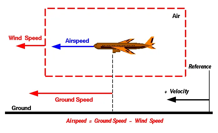
Airspeed is the vector difference between the ground speed and the wind speed. On a perfectly still day, the airspeed is equal to the ground speed. But if the wind is blowing in the same direction that the aircraft is moving, the airspeed will be less than the ground speed.
Airspeed
The important quantity in the generation of lift is the relative velocity between the object and the air, which is called the airspeed. Airspeed cannot be directly measured from a ground position, but must be computed from the ground speed and the wind speed. Airspeed is the vector difference between the ground speed and the wind speed.
Airspeed = Ground Speed - Wind Speed
On a perfectly still day, the airspeed is equal to the ground speed. But if the wind is blowing in the same direction that the aircraft is moving, the airspeed will be less than the ground speed.
Wind Speed
For a reference point picked on the ground, the air moves relative to the reference point at the wind speed. Notice that the wind speed is a vector quantity and has both a magnitude and a direction. Direction is important. A 20 mph wind from the west is different from a 20 mph wind from the east. The wind has components in all three primary directions (north-south, east-west, and up-down). In this figure, we are considering only velocities along the aircraft's flight path. A positive velocity is defined to be in the direction of the aircraft's motion. We are neglecting cross winds, which occur perpendicular to the flight path but parallel to the ground, and updraft & downdraft, which occur perpendicular to the ground.
Ground Speed
For a reference point picked on the ground, the aircraft moves relative to the reference point at the ground speed. Ground speed is also a vector quantity so a comparison of the ground speed to the wind speed must be done according to rules for vector comparisons.
Suppose we had an airplane that could take off on a windless day at 100 mph (liftoff airspeed is 100 mph). We are at an airport with an east-west runway that is 1 mile long. The wind is blowing 20 mph towards the west and the airplane takes off going east. The wind is blowing towards the aircraft which we call a headwind. Since we have defined a positive velocity to be in the direction of the aircraft's motion, a headwind is a negative velocity. While the plane is sitting still on the runway, it has a ground speed of 0 and an airspeed of 20 mph:
Airspeed = Ground Speed (0) - Wind Speed (-20) = 20 mph
The airplane starts its take off roll and has a constant acceleration a. From Newton's second law of motion, the ground speed V at any time t is:
V = a * t
and the distance d down the runway at any time is: d = 1/2 * a * t^2
For a fixed length runway, this specifies the time to be used in the velocity equation. Let's assume that at 5000 feet down the runway, the velocity is 80 mph. Then the airspeed is given by
Airspeed = Ground Speed (80) - Wind Speed (-20) = 100 mph
and the airplane begins to fly. Now another pilot, with exactly the same airplane decides to take off to the west. The wind is now in the same direction as the motion and this is called a tailwind. The sign on the wind speed is now positive, not negative as with the headwind. The acceleration along the ground is the same, so at 5000 feet down the runway, the ground speed is again 80 mph. The airspeed is then given by:
Airspeed = Ground Speed (80) - Wind Speed (20) = 60 mph
This airplane doesn't have enough airspeed to fly. It runs off the end of the runway!
3. Why is it not recommended to use aircraft engine power to move it on the ground at Airport?
High engine thrust during maintenance activity can cause considerable damage to airplanes and other elements in the airport environment. An example of this problem occurred after an airplane arrived at its final destination with a log entry indicating the flight crew had experienced anomalous engine operation.
All large aircraft are pushed back , they could use there power to do it but due to the noise and fumes plus they burn a lot of fuel.
Airplanes get towed or pushed by tractors and tugs when jet blast from their engines or prop wash from their propellers will create a hazard to nearby buildings, ground crew, other aircraft & ground handling equipment. Moving aircraft from hangers to aprons does not require pilots if being towed.
Depending on the airport, some aircraft movements have to be made with assistance to ensure the safety of all those working in the area or when the need to start the engines is overkill for the maintenance task required.
When aircraft go in for maintenance or are not required for flight by far the easiest way is to send a tow vehicle to the gate and have the maintenance team tow the aircraft to the hanger or parking areas. By doing this it allows time freedom for the airline, the airport ground controllers, and the maintenance team as pilots are not required to start the engines.
When an aircraft is being towed, trained and authorized maintenance personnel will be on board the aircraft to release and control the brakes to aid the tow vehicle operator.
Some airplanes will need to have their APU (Auxillary Power Unit) started by the maintenance personnel so that electrical and hydraulic systems can be operational to operate the braking systems and aircraft lights when towing at night.
Some tow vehicles may have the ability to hook up to the aircraft to negate the need to start the APU, making the towing process simpler and save fuel that the APU would burn.
Another reason you might see or experience being towed is when your aircraft has to be towed from the taxiway to the gate. This will be due to the tight confines of the terminal gates and the restricted view the pilots have may require a tow to conduct the arrival safely. As airplanes become larger and airports get busier you may see this quite often.
Even though pilots follow taxi centerlines, airplanes with very large wingspans could create tight spots and any contact made between two aircraft can cause significant damage, lost time, and potentially huge costs, so a simple tow helps prevent this.
4. How an aircraft is pushed to runway when its ready to take off?
The airplane may be pushed or pulled by landing gear or wing struts since they're known to be strong enough to drag the airplane through the air. To allow for turns, a person may either pick up or push down on the tail to raise either the nose wheel or tail wheel off the ground, then rotate the airplane by hand.
Pushbacks at busy aerodromes are usually subject to ground control clearance to facilitate ground movement on taxiways. Once clearance is obtained, the pilot will communicate with the tractor driver (or a ground handler walking alongside the aircraft in some cases) to start the pushback. To communicate, a headset may be connected near the nose gear.
Since the pilots cannot see what is behind the aircraft, steering is done by the pushback tractor driver and not by the pilots. Depending on the aircraft type and airline procedure, a bypass pin may be temporarily installed into the nose gear to disconnect it from the aircraft's normal steering mechanism.
Once the pushback is completed, the towbar is disconnected, and any bypass pin removed. The ground handler will show the bypass pin to the pilots to make it clear that it has been removed. The pushback is then complete, and the aircraft can taxi forward under its own power.
Moving light aircraft
Very small airplanes may be moved by human power alone. The airplane may be pushed or pulled by landing gear or wing struts since they're known to be strong enough to drag the airplane through the air. To allow for turns, a person may either pick up or push down on the tail to raise either the nose wheel or tail wheel off the ground, then rotate the airplane by hand.
Tractors and towbars
Large aircraft cannot be moved by hand and must have a tractor or tug. Pushback tractors use a low profile design to fit under the aircraft nose. For sufficient traction the tractor must be heavy, and most models can have extra ballast added. A typical tractor for large aircraft weighs up to 54 tonnes (59.5 short tons; 53.1 long tons; 119,000 pounds) and has a drawbar pull of 334 kN (75,000 lbf). Often the driver's cabin can be raised for increased visibility when reversing and lowered to fit under aircraft.
There are two types of pushback tractors: conventional and towbarless (TBL).
Towbarless (TBL) tractors do not use a towbar; they scoop up the nose landing gear and lift it off the ground. This avoids the time penalty of connecting/disconnecting a towbar, and entirely removes the cost/complexity of maintaining towbars on the ramp. The tug itself does not need to be particularly massive - the aircraft's nosewheel weight provides the necessary downward force. Lastly, a TBL tug is much shorter (compared to a tug+towbar system) and has one only a single pivot point instead of one at either end of the towbar, so it has much simpler and precise control of the aircraft. This is very useful in general aviation settings with a wider variety of aircraft in more confined spaces than their airline counterparts
 Pushback tug with the towbar behind

5. Learn about take off power, tyre design, rolling resistance, tyre pressure, brake forces when landing.
TAKE-OFF POWER IN AIRCRAFT:
The amount of power that an engine is allowed to produce for a limited period of time for takeoff. The use of takeoff power is usually limited to 5 min for reciprocating engines and up to 2½ min for gas turbine engines.
Most takeoffs use "derated" thrust to save engine wear. For each takeoff, performance is calculated, the necessary power setting is determined and the thrust setting is made. When using this method during takeoff, it is always possible to increase to full power if the situation requires.
TAKE OFF AND LANDING
Take Off Performance
Take off performance can be predicted using a simple measure of the acceleration of the aircraft along the runway based on force equilibrium.
The forces involved will be,
T – Thrust of propulsion system pushing aircraft along runway.
D – Aerodynamic Drag of vehicle resisting the aircraft motion.
F – Rolling resistance friction due to the contact of wheels or skids on the ground.
During take-off run the imbalance in these forces will produce an acceleration along the runway.
(dv/dt)=(T-D-F)/m
where dV/dt is the acceleration along the runway and m is the mass of the vehicle.
Rotation Velocity, VR
The procedure for take-off will be that the vehicle will accelerate until it reaches a safe initial flying speed. The pilot can then rotate the vehicle to an attitude to produce climb lift and it will ascend from the ground. The determination of this safe flying speed or rotation speed, VR, is a critical factor in determining take-off performance.
Take-off rules vary slightly depending on the aircraft category. Small commuter aircraft should be considered as meeting FAR 23 rules, transport category aircraft should comply with FAR 25 rules.
Small commuter aircraft :
For safety reasons VR is usually determined as being 1.1 × VSTALL or 1.05 × VMIN CONTROL
which ever is greater. Stall speed, VSTALL, is the lowest speed that the aircraft can be flown before the airflow starts to separate from wings as the angle of attack becomes too great. The wing is assumed in this case to be in take-off configuration or "clean".
It can be calculated based on knowledge of the aircraft take-off configuration and hence the maximum achievable lift coefficient CL(max). As shown in the previous section , to maintain level flight the lift produced must equal the weight, hence the stall speed can be calculated as,
Vstall=√ W 1 2 CL(max)ρS
Minimum control speed, VMC is a more complex calculation and requires knowledge of the stall characteristics of the tailplane and elevator. For conventional aircraft there is only a small difference between VR calculations based on stall speed or minimum control speed.
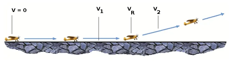
V1- Abort decision speed. Below this speed the take-off can be safely aborted. After this there will not be sufficient runway length to allow the aircraft to decelerate to a stop.
V2 – Safe climb speed. V2 must be no less than 1.2 * Vstall. Below this speed aircraft cannot attain sufficient climb rate.
Thrust
The thrust of gas turbine or turbofan engines will be relatively constant during take-off. A good assumption is to use the manufacturer's values for maximum static thrust for take-off calculations.
The thrust of a propeller driven aircraft can be found from the given shaft horsepower data for the engine and the use of the equations using propeller efficiency given in the previous section.
T= Pshaft×η V
It is critical to correctly estimate the propeller efficiency for the particular aircraft velocity along the runway. At V=0 the efficiency is 0 so the above equation makes no sense. At V=VR the efficiency will be in the range 50% to 80% depending on the type of propeller system used and the thrust value at this point will be easy to obtain. In practice, the thrust obtained throughout the take-off roll is roughly constant so this end point value is a good approximation from V=0 to V=VR
Drag
The resistance to motion due to the air viscosity will give a drag of
D=CD 1 2 ρ.V2S
where CD can be considered constant and calculated using the formula shown in the previous section
Although Drag Coefficient is constant, Drag will increase in proportion to the square of velocity.
Rolling Resistance
The friction between aircraft and runway will be proportional to the normal force exerted by the aircraft on the runway.
F=μ(W−L)
The normal force will be the difference between Weight of aircraft and Lift, the friction coefficient will be typically of a magnitude of 0.02 for a standard tarmac runway.
The rate of change of velocity can be predicted at any point on the take-off roll by substituting results for T, D and F into the initial equation for dV/dt. The subsequent velocity at any point can be found by integrating this resulting equation and the distance traveled found by then integrating the velocity.
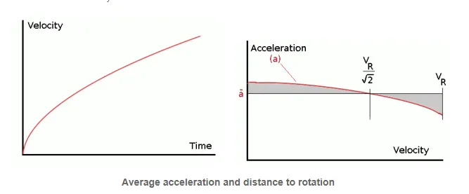
Typically acceleration will be dominated by the drag component as thrust, weight and friction are relatively constant during this period. This leads to the result shown where acceleration is inversely proportional to velocity squared.
Due to the quadratic nature of acceleration change, an average value, (dV /dt )avg= − a , can be used for the take-off run. This average acceleration can be found at the point where,
V= VR √2
This average acceleration can be used to simplify calculations and the take-off run can be calculated as an equivalent constant acceleration over the complete period of time (tR) taken to get from 0 to VR. For a constant acceleration take-off calculation,
VR= − a tR and distance travelled s= 1 2 − a tR2
Rearranging leads to a relatively simple calculation to predict distance to rotation point.
s1= 1 2 VR2 − a
Take-Off (Balanced) Field Length
The required length of runway will be the sum of the distance required to get to rotation speed and the extra length required to clear a 50ft obstacle or the extra length required to allow for rapid braking if the pilot decides to abort take-off at the decision speed V1.
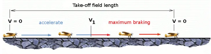
This length will typically be considerably longer than the distance required to achieve rotation (flying) speed. A rough approximation is that runway total length is around 2 x s1
Distance to V1 can be calculated in a manner similar to that shown for VR. The calculation of braking distance will require knowledge of the maximum braking friction coefficient that can be generated by the aircraft. This information should be available from manufacturer's data. Braking distance calculations should also be done without any assumption of reverse thrust from engines as during a take-off abort, engine power may not be available.
Landing
The landing run can be calculated in a similar fashion to the take off distance. The aim is again to minimise the distance.
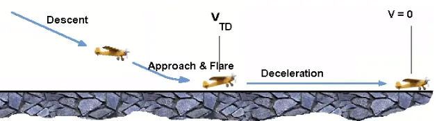
The touch down velocity should be approximately the stall speed of the aircraft in landing configuration. This will be achieved by a pitch manoeuvre during the flare portion of the approach which which increase drag an decelerate the aircraft to minimum flying speed.
The deceleration on the landing roll from VTD to V0 will be accomplished by braking and reverse thrust. This can be solved by the average acceleration approach that was used to estimate the take-off roll.
dV dt = −T−D−F m
The negative acceleration or deceleration value will be based on friction coefficient for maximum braking and the value of reverse thrust (if available).
Tire Design
Designing aircraft tires is a very intense undertaking. Once an aircraft manufacturer goes to the tire manufacturer with the size and weight requirements, the tire manufacturer begins the process of designing a tire that meets the needs of the aircraft manufacturer as well as all regulatory requirements — including foreign regulations in many cases.
Engineers are challenged with designing tires with cool running, heat-resistant materials while simultaneously exceeding tire service requirements. Tire prototypes are put through rigorous tests that simulate cycles of landings, take-offs, and taxi operations. It is only after the tires pass all mandatory tests and meet the requirements of the aircraft manufacturer and airworthiness authorities that the tires are put into production.
Two types of tires are used in aircraft applications — bias-ply tires and radial tires. Although both types of tires share some similarities in design, there are differences that need to be noted.
Bias-ply tire construction
Bias-ply tires are popular choices for aircraft tires because of their durability and retread ability.
Tread: The tread is made of rubber mixed with other additives to obtain the desired level of toughness, durability, and resistance to wear. The tread pattern is designed to aircraft operational requirements, with the ribbed tread design used widely due to its good traction under varying runway conditions.
Sidewall: The sidewall is a protective layer of rubber that covers the outer casing ply. It extends from the tread edge to the bead area.
Tread Reinforcing Ply: One or more layers of fabric that strengthens and stabilizes the tread area for high-speed operation. It also serves as a reference for the buffing process when tires are retreaded.
Buff Line Cushion: The buff line cushion is made of rubber compound to enhance the adhesion between the tread reinforcing ply and the breakers or casing plies. It is of sufficient thickness to allow for the removal of the old tread when the tire is retreaded.
Breakers: Breakers are reinforcing plies of rubber-coated fabric placed under the buff line cushion to protect casing plies and strengthen and stabilize the tread area. They are considered an integral part of the casing construction.
Casing Plies: Alternate layers of rubber-coated fabric (running at opposite angles to one another) provide the strength of the tire.
Wire Beads: Hoops of high tensile strength steel wire that anchor the casing plies and provides a firm mounting surface on the wheel. The outer edge of the bead that fits against the wheel flange is called the bead heel. The inner bead edge is called the bead toe.
Apex Strip: A wedge of rubber affixed to the top of the bead bundle.
Flippers: Layers of rubberized fabric that help anchor the bead wires to the casing and improve the durability of the tire.
Ply Turnups: The casing plies are anchored by wrapping them around the wire beads, thus forming the ply turnups.
Chafer: A protective layer of rubber and/or fabric located between the casing plies and wheel to minimize chafing.
Liner: In tubeless tires, the liner is a layer of low permeability rubber that acts as a built-in tube and restricts gas from diffusing into the casing plies. In tube-type tires, a thinner liner is used to prevent tube chafing against the inside ply.
Radial-ply tire construction
A typical radial tire is illustrated in Figure 2. With their rigid belt, they provide increased landings and reduced rolling resistance. They have fewer components in their construction and are lighter than similarly sized bias ply tires.
Overlay: A layer of reinforcing rubber coated fabric placed on top of the belts to aid in high speed operation.
Belt Plies: A composite structure that stiffens the tread area for increased landings. The belt plies increase the tire strength in the tread area.
Casing Plies: As in bias-ply tires, the casing plies are layers of rubber-coated fabric. However, unlike those in bias plies that run at opposite angles to one another, radial plies run radially from bead to bead.
Chippers: The chippers are layers of rubber-coated fabric applied at diagonal angles that improve the durability of the tire in the bead area.
Part B:
6. A. With necessary assumptions, calculate the force and power required to push / pull an aircraft by a towing vehicle.
B. Develop the model for the calculated force and power using Simulink.
7. A. Design an electric powertrain with type of motor, it’s power rating, and energy requirement to fulfill aircraft towing application in Simulink. Estimate the duty cycle range to control the aircraft speed from zero to highest. Make all required assumptions. Prepare a table of assumed parameters. Draw a block diagram of powertrain.
(Hint :DC7 Block)
B. Also, Design the parameters in excel sheet.