Project-1: Powertrain for aircraft in runways
PART A:-
STUDY 1:
1.(A) list out the total weight of various types of aircrafts:
The aircraft gross weight (also known as the all-up weight and abbreviated AUW) is the total aircraft weight at any moment during the flight or ground operation.
An aircraft's gross weight will decrease during a flight due to fuel and oil consumption. An aircraft's gross weight may also vary during a flight due to payload dropping.
At the moment of releasing its brakes, the gross weight of an aircraft is equal to its takeoff weight. During flight, an aircraft's gross weight is referred to as the en-route weight or in-flight weight.
This is a list of aircraft sorted by Maximum take-off Weight.
| Type | MTOW [kg] | MLW [tonnes] | TOR [m] | LR [m] | ICAO category | FAA category |
|---|---|---|---|---|---|---|
| Antonov An-225 | 640,000 | 591.7 | 3500 | Heavy | Super | |
| Scaled Composites Model 351 Stratolaunch | 589,670 | 3660 | Heavy | Super | ||
| Airbus A380-800[1][2][3] | 575,000 | 394 | 3100 | 1930 | Super | Super |
| Boeing 747-8F | 447,700 | 346.091 | 3100 | 1800 | Heavy | Heavy |
| Boeing 747-8 | 443,613 | 306.175 | 3100 | Heavy | Heavy | |
| Boeing 747-400ER | 412,770 | 295.742 | 3090 | Heavy | Heavy | |
| Antonov An-124-100M | 405,060 | 330 | 2520 | 900 | Heavy | Heavy |
| Boeing 747-400 | 396,900 | 295.742 | 3018 | 2179 | Heavy | Heavy |
| Lockheed C-5 Galaxy[4][5][6] | 381,000 | 288.417 | 2530 | 1494 | Heavy | Heavy |
| Boeing 747-200[7] | 377,840 | 285.700 | 3338 | 2109 | Heavy | Heavy |
| Boeing 747-300[7] | 377,840 | 260.320 | 3222 | 1905 | Heavy | Heavy |
| Airbus A340-500[8] | 371,950 | 240 | 3050 | 2010 | Heavy | Heavy |
| Airbus A340-600[8] | 367,400 | 256 | 3100 | 2100 | Heavy | Heavy |
| Boeing 777F | 347,800 | 260.816 | 2830 | Heavy | Heavy | |
| Boeing 777-300ER | 351,800 | 251.29 | 3100 | Heavy | Heavy | |
| Boeing 777-200LR | 347,450 | 223.168 | 3000 | Heavy | Heavy | |
| Boeing 747-100[7] | 340,200 | 265.300 | Heavy | Heavy | ||
| Airbus A350-1000 | 308,000 | 233.5 | Heavy | Heavy | ||
| Boeing 777-300 | 299,370 | 237.683 | 3380 | Heavy | Heavy | |
| Boeing 777-200ER | 297,550 | 213.00 | 3380 | 1550 | Heavy | Heavy |
| Airbus A340-300[8][9] | 276,700 | 190 | 3000 | 1926 | Heavy | Heavy |
| McDonnell Douglas MD-11 | 273,300 | 185 | 2990 | 1890 | Heavy | Heavy |
| Airbus A350-900 | 270,000 | 175 | 2670 | 1860 | Heavy | Heavy |
| Ilyushin Il-96M | 270,000 | 195.04 | 3115 | 2118 | Heavy | Heavy |
| McDonnell Douglas DC-10 | 256,280 | 183 | 2990 | 1890 | Heavy | Heavy |
| Boeing 787-9[10] | 254,000 | 192.777 | 2900 | Heavy | Heavy | |
| Boeing 787-10[10] | 254,000 | 201.849 | Heavy | Heavy | ||
| Airbus A340-200[8][11] | 253,500 | 181 | 2990 | Heavy | Heavy | |
| Airbus A330-900 | 251,000 | 191,000 | 3100 | Heavy | Heavy | |
| Ilyushin IL-96-300 | 250,000 | 175 | 2600 | 1980 | Heavy | Heavy |
| Airbus A330-300[12][13] | 242,000 | 185 | 2500 | 1750 | Heavy | Heavy |
| Airbus A330-200[12][13] | 242,000 | 180 | 2220 | 1750 | Heavy | Heavy |
| Lockheed L-1011-500 | 231,300 | 166.92 | 2636 | Heavy | Heavy | |
| Boeing 787-8[10] | 228,000 | 172.365 | 3300 | 1695 | Heavy | Heavy |
| Lockheed L-1011-200 | 211,400 | Heavy | Heavy | |||
| Ilyushin IL-86 | 208,000 | 175 | Heavy | Heavy | ||
| Boeing 767-400ER | 204,000 | 158.758 | 3414 | Heavy | Heavy | |
| Airbus A300-600R[14] | 192,000 | 140 | 2385 | 1555 | Heavy | Heavy |
| Boeing 767-300ER | 187,000 | 136.08 | 2713 | 1676 | Heavy | Heavy |
| Concorde | 185,000 | 111.1 | 3440 | 2220 | Heavy | Heavy |
| Airbus A300-600[14] | 163,000 | 138 | 2324 | 1536 | Heavy | Heavy |
| Boeing 767-300 | 159,000 | 136.078 | 2713 | 1676 | Heavy | Heavy |
| Airbus A310-300[14] | 157,000 | 124 | 2290 | 1490 | Heavy | Heavy |
| Vickers VC10 | 152,000 | 151.9 | Heavy | Heavy | ||
| Boeing 707-320B[15] | 151,000 | 97.5 | Heavy | Heavy | ||
| Boeing 707-320C[15] | 151,000 | 112.1 | Heavy | Heavy | ||
| Douglas DC-8-61 | 147,000 | Heavy | Heavy | |||
| Airbus A310-200[14] | 142,000 | 123 | 1860 | 1480 | Heavy | Heavy |
| Airbus A400M | 141,000 | 122 | 980 | 770 | Heavy | Heavy |
| Douglas DC-8-32 | 140,000 | Heavy | Heavy | |||
| Douglas DC-8-51 | 125,000 | Medium | Large | |||
| Boeing 757-300 | 124,000 | 101.6 | 2550 | 1750 | Medium | Large |
| Boeing 707-120B[15] | 117,000 | 86.3 | Medium | Large | ||
| Boeing 757-200 | 116,000 | 89.9 | 2347 | 1555 | Medium | Large |
| Boeing 720B[16] | 106,000 | 79.5 | Medium | Large | ||
| Boeing 720[16] | 104,000 | 79.5 | Medium | Large | ||
| Tupolev Tu-154M | 104,000 | 80 | Medium | Large | ||
| Tupolev Tu-204SM | 104,000 | 87.5 | 2250 | Medium | Large | |
| Convair 880 | 87,500 | Medium | Large | |||
| Boeing 737-900 | 85,000 | 66.36 | 2500 | 1704 | Medium | Large |
| Boeing 737-900ER | 85,000 | 71.35 | 2804 | 1829 | Medium | Large |
| Boeing 727-200 Advanced[17] | 84,000 | 70.1 | Medium | Large | ||
| Airbus A321-100[18] | 83,000 | 77.8 | 2200 | 1540 | Medium | Large |
| Boeing 737-800 | 79,000 | 65.32 | 2308 | 1634 | Medium | Large |
| Boeing 727-200[17] | 78,000 | 68.1 | Medium | Large | ||
| McDonnell-Douglas MD-83 | 73,000 | 63.28 | Medium | Large | ||
| Boeing 727-100[17] | 72,500 | 62.4 | Medium | Large | ||
| Boeing 727-100C[17] | 72,500 | 62.4 | Medium | Large | ||
| McDonnell-Douglas MD-90-30 | 71,000 | 64.41 | 2165 | 1520 | Medium | Large |
| de Havilland Comet 4 | 70,700 | Medium | Large | |||
| Boeing 737-700 | 70,000 | 58.06 | 1921 | 1415 | Medium | Large |
| Airbus A320-100[18] | 68,000 | 66 | 1955 | 1490 | Medium | Large |
| Boeing 737-400 | 68,000 | 54.9 | 2540 | 1540 | Medium | Large |
| de Havilland Comet 3 | 68,000 | Medium | Large | |||
| Boeing 377 | 67,000 | Medium | Large | |||
| Boeing 737-600 | 66,000 | 54.66 | 1796 | 1340 | Medium | Large |
| Airbus A220-300 | 65,000 | 57.61 | 1890 | 1494 | Medium | Large |
| Hawker Siddeley Trident 2E | 65,000 | Medium | Large | |||
| Airbus A319[18] | 64,000 | 62.5 | 1850 | 1470 | Medium | Large |
| Boeing 737-300 | 63,000 | 51.7 | 1939 | 1396 | Medium | Large |
| Boeing 737-500 | 60,000 | 49.9 | 1832 | 1360 | Medium | Large |
| Airbus A220-100 | 59,000 | 50.80 | 1463 | 1356 | Medium | Large |
| Airbus A318[18] | 59,000 | 57.5 | 1375 | 1340 | Medium | Large |
| Boeing 717-200HGW | 55,000 | 47.174 | 1950 | Medium | Large | |
| Douglas DC-7 | 55,000 | Medium | Large | |||
| de Havilland Comet 2 | 54,000 | Medium | Large | |||
| Boeing 717-200BGW | 50,000 | 46.265 | 1950 | Medium | Large | |
| de Havilland Comet 1 | 50,000 | Medium | Large | |||
| Douglas DC-6A | 48,600 | Medium | Large | |||
| Douglas DC-6B | 48,500 | Medium | Large | |||
| Embraer 190[19] | 48,000 | 43 | 2056 | 1323 | Medium | Large |
| Caravelle III | 46,000 | Medium | Large | |||
| Fokker 100 | 46,000 | 39.95 | 1621 | 1350 | Medium | Large |
| Douglas DC-6 | 44,000 | Medium | Large | |||
| Avro RJ-85 | 42,000 | 36.74 | Medium | Large | ||
| Handley Page Hermes | 39,000 | Medium | Large | |||
| Embraer 175[20] | 37,500 | 32.8 | 2244 | 1304 | Medium | Large |
| Bombardier CRJ900[21] | 36,500 | 33.345 | 1778 | 1596 | Medium | Large |
| Embraer 170[22] | 36,000 | 32.8 | 1644 | 1274 | Medium | Large |
| Bombardier CRJ700 | 33,000 | 30.39 | 1564 | 1478 | Medium | Large |
| Douglas DC-4 | 33,000 | Medium | Large | |||
| Vickers Viscount 800 | 30,400 | Medium | Large | |||
| Bombardier Q400 | 28,000 | 28.01 | 1219 | 1295 | Medium | Large |
| Bombardier CRJ200 | 23,000 | 21.319 | 1918 | 1479 | Medium | Large |
| ATR 72-600 | 22,800 | 22.35 | 1333 | 914 | Medium | Large |
| Saab 2000 | 22,800 | 21.5 | 1300 | Medium | Large | |
| Embraer ERJ 145 | 22,000 | 19.3 | 2270 | 1380 | Medium | Large |
| ATR 42-500 | 18,600 | 18.3 | 1165 | 1126 | Medium | Small |
| Saab 340 | 13,150 | 12.930 | 1300 | 1030 | Medium | Small |
| Embraer 120 Brasilia | 11,500 | 11.25 | 1560 | 1380 | Medium | Small |
| BAe Jetstream 41 | 10,890 | 10.570 | 1493 | 826 | Medium | Small |
| Learjet 75[23] | 9,752 | 8.709 | 1353 | 811 | Medium | Small |
| Pilatus PC-24[24] | 8,300 | 7.665 | 893 | 724 | Medium | Small |
| Embraer Phenom 300[25] | 8,150 | 7.65 | 956 | 677 | Medium | Small |
| Beechcraft 1900D | 7,765 | 7.605 | 1036 | 853 | Medium | Small |
| Cessna Citation CJ4[26] | 7,761 | 7.103 | 1039 | 896 | Medium | Small |
| de Havilland Hercules | 7,000 | Medium | Small | |||
| Embraer Phenom 100 | 4,800 | 4.43 | 975 | 741 | Light | Small |
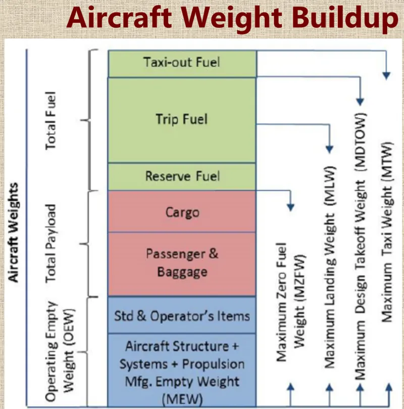
An aircraft's gross weight is limited by several weight restrictions in order to avoid overloading its structure or to avoid unacceptable performance or handling qualities while in operation.
Aircraft gross weight limits are established during an aircraft's design and certification period and are laid down in the aircraft's type certificate and manufacturer specification documents.
The absolute maximum weight capabilities of a given aircraft are referred to as the structural weight limits. The structural weight limits are based on aircraft maximum structural capability and define the envelope for the CG charts (both maximum weight and CG limits).
An aircraft's structural weight capability is typically a function of when the aircraft was manufactured, and in some cases, old aircraft can have their structural weight capability increased by structural modifications.
Maximum design taxi weight (MDTW)
The maximum design taxi weight (also known as the maximum design ramp weight (MDRW)) is the maximum weight certificated for aircraft manoeuvring on the ground (taxiing or towing) as limited by aircraft strength and airworthiness requirements.
Maximum design takeoff weight (MDTOW)
Is the maximum certificated design weight when the brakes are released for takeoff and is the greatest weight for which compliance with the relevant structural and engineering requirements has been demonstrated by the manufacturer.
Maximum design landing weight (MDLW)
The maximum certificated design weight at which the aircraft meets the appropriate landing certification requirements. It generally depends on the landing gear strength or the landing impact loads on certain parts of the wing structure.
The MDLW must not exceed the MDTOW.
The maximum landing weight is typically designed for 10 feet per second (600 feet per minute) sink rate at touch down with no structural damage.
Maximum design zero-fuel weight (MDZFW)
The maximum certificated design weight of the aircraft less all usable fule and other specified usable agents (engine injection fluid, and other consumable propulsion agents). It is the maximum weight permitted before usable fuel and other specified usable fluids are loaded in specified sections of the airplane. The MDZFW is limited by strength and airworthiness requirements. At this weight, the subsequent addition of fuel will not result in the aircraft design strength being exceeded. The weight difference between the MDTOW and the MDZFW may be utilised only for the addition of fuel.
Minimum flight weight (MFW)
Minimum certificated weight for flight as limited by aircraft strength and airworthiness requirements.
2.(A)difference between ground speed and air speed?
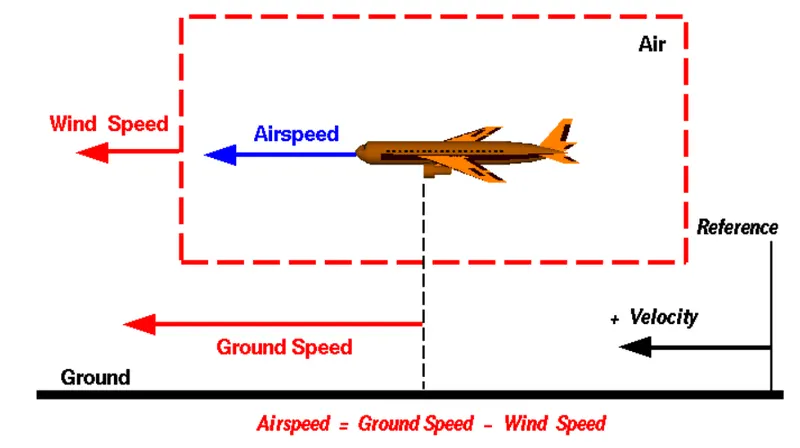
Wind Speed
For a reference point picked on the ground, the air moves relative to the reference point at the wind speed. Notice that the wind speed is a vector quantity and has both a magnitude and a direction. Direction is important. A 20 mph wind from the west is different from a 20 mph wind from the east. The wind has components in all three primary directions (north-south, east-west, and up-down). In this figure, we are considering only velocities along the aircraft's flight path. A positive velocity is defined to be in the direction of the aircraft's motion. We are neglecting cross winds, which occur perpendicular to the flight path but parallel to the ground, and updrafts and downdrafts, which occur perpendicular to the ground.
Ground Speed
For a reference point picked on the ground, the aircraft moves relative to the reference point at the ground speed. Ground speed is also a vector quantity so a comparison of the ground speed to the wind speed must be done according to rules for vector comparisions.
Airspeed
The important quantity in the generation of lift is the relative velocity between the object and the air, which is called the airspeed. Airspeed cannot be directly measured from a ground position, but must be computed from the ground speed and the wind speed. Airspeed is the vector difference between the ground speed and the wind speed.
Airspeed = Ground Speed - Wind Speed
On a perfectly still day, the airspeed is equal to the ground speed. But if the wind is blowing in the same direction that the aircraft is moving, the airspeed will be less than the ground speed.
3.(A)Why is it not recommended to use aircraft engine power to move it on the ground at Airport?
Taxiing (rarely spelled taxying) is the movement of an aircrafts on the ground, under its own power, in contrast to towing or pushback where the aircraft is moved by a tug. The aircraft usually moves on wheels, but the term also includes aircraft with skis or floats (for water-based travel).
An airplane uses taxiways to taxi from one place on an airport to another; for example, when moving from a hanger to the runway. The term "taxiing" is not used for the accelerating run along a runway prior to take-off, or the decelerating run immediately after landing, which are called the takeoff roll and landing rollout, respectively.
4.(A)How an aircraft is pushed to runway when its ready to take off?
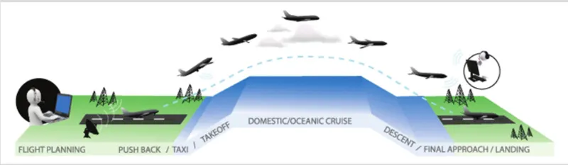
Take-Off:
Takeoff is the phase of flight in which an aircraft goes through a transition from moving along the ground (taxiing) to flying in the air, usually starting on a runway. Usually the engines are run at full power during takeoff. Following the taxi motion, the aircraft stops at the starting line of the runway. Before takeoff, the engines, particularly piston engines, are routinely run up at high power to check for engine-related problems. This makes a consid- erable noise. When the pilot releases the brakes, the aircraft starts accelerating rapidly until the necessary speed for take-off is achieved.
The takeoff speed required varies with air den- sity, aircraft weight, and aircraft configuration (flap and/or slat position, as applicable). Air density is affected by factors such as field ele- vation and air temperature.
Operations with transport category aircraft employ the concept of the takeoff V-Speeds, V1 and V2. These speeds are determined not only by the above factors affecting takeoff perform- ance, but also by the length and slope of the runway. Below V1, in case of critical failures, the takeoff should be aborted; above V1 the pilot continues the takeoff and returns for land- ing. After the co-pilot calls V1, Then, V2 (the safe takeoff speed) is called. This speed must be maintained after an engine failure to meet per- formance targets for rate of climb and angle of climb.
The speeds needed for takeoff are relative to the motion of the air (indicated airspeed). A head wind will reduce the ground speed needed for takeoff, as there is a greater flow of air over the wings. This is why the aircrafts always take off against the wind. Side wind is not preferred as it would disturb the stability of the aircraft. Typical takeoff air speeds for jetliners are in the 130–155 knot range (150–180 mph, 240–285 km/h). For a given aircraft, the takeoff speed is usually directly proportional to the aircraft weight; the heavier the weight, the greater the speed needed. Some aircraft have difficulty generating enough lift at the low speeds encountered during takeoff. These are therefore fitted with high-lift devices, often including slats and usually flaps, which increase the camber of the wing, making it more effective at low speed, thus creating more lift. These have to be deployed from the wing before performing any maneuver.
At the beginning of the climb phase, the wheels are retracted into the aircraft and the undercarriage doors are closed. This operation is audible by the passengers as a noise coming from below the floor.
Climb:
Following take-off, the aircraft has to climb to a certain altitude (typically 30,000 ft or 10 km) before it can cruise at this altitude in a safe and economic way. A climb is carried out by increasing the lift of wings supporting the aircraft until their lifting force exceeds the weight of the aircraft. Once this occurs, the aircraft will climb to a higher altitude until the lifting force and weight are again in balance. The increase in lift may be accomplished by increasing the angle of attack of the wings, by increasing the thrust of the engines to increase speed (thereby increasing lift), by increasing the surface area or shape of the wing to produce greater lift, or by some combination of these techniques. In most cases, engine thrust and angle of attack are simultaneously increased to produce a climb.
Because lift diminishes with decreasing air density, a climb, once initiated, will end by itself when the diminishing lift with increasing altitude drops to a point that equals the weight of the aircraft. At that point, the aircraft will return to level flight at a constant altitude. During climb phase, it is normal that the engine noise diminishes. This is because the engines are operated at a lower power level after the take-off. It is also possible to hear a whirring noise or a change in the tone of the noise during climb. This is the sound of the flaps that are retracting. A wing with retracted flap produces less noise.
Cruise:
Cruise is the level portion of aircraft travel where flight is most fuel efficient. It occurs between ascent and descent phases and is usually the majority of a journey. Technically, cruising consists of heading (direction of flight) changes only at a constant airspeed and altitude. It ends as the aircraft approaches the destination where the descent phase of flight commences in preparation for landing.
For most commercial passenger aircraft, the cruise phase of flight consumes the majority of fuel. As this lightens the aircraft considerably, higher altitudes are more efficient for additional fuel economy. However, for operational and air traffic control reasons it is necessary to stay at the cleared flight level. Typical cruising speed for long-distance commercial passenger flights is 475-500 knots (878-926 km/h; 547-578 mph).
Commercial or passenger aircraft are usually designed for optimum performance at their cruise speed. There is also an optimum cruise altitude for a particular aircraft type and conditions including payload weight, center of gravity, air temperature, humidity, and speed. This altitude is usually where the drag is minimum and the lift is maximum. As in any phase of the flight, the aircraft in cruise mode is always in communication with an Air Traffic Control (ATC) station. Although the general tendency is to follow a straight line towards the destination, there may be some deviations from the flight plan for weather, turbulence or air traffic rea- sons, after receiving clearance from ATC. Descent
Descent:
A descent during air travel is any portion where an aircraft decreases altitude. Descents are an essential component of an approach to landing. Other partial descents might be to avoid traffic, poor flight conditions (turbulence or bad weather), clouds (particularly under visual flight rules), to see something lower, to enter warmer air (in the case of extreme cold), or to take advantage of wind direction of a different altitude. Normal descents take place at a con- stant airspeed and constant angle of descent (3 degree final approach at most airports). The pilot controls the angle of descent by varying engine power and pitch angle (lowering the nose) to keep the airspeed constant.
At the beginning of and during the descent phase, the engine noise diminishes further as the engines are operated at low power settings. However, towards the end of the descent phase, the passenger can feel further accelerations and an increase in the noise. This is to realize the “final approach” before taking “landing posi- tion”.
Landing:
Landing is the last part of a flight, where the aircraft returns to the ground. Aircraft usually land at an airport on a firm runway, generally constructed of asphalt concrete, concrete, gravel or grass. To land, the airspeed and the rate of descent are reduced to where the object descends at a slow enough rate to allow for a gentle touch down. Landing is accomplished by slowing down and descending to the runway. This speed reduction is accomplished by reducing thrust and/or inducing a greater amount of drag using flaps, landing gear or speed brakes. As the plane approaches the ground, the pilot will execute a flare (roundout) to induce a gentle landing. Although the pilots are trained to perform the landing operation, there are “Instrument Landing Systems” in most of the airports to help pilots land the aircrafts. An instrument landing system (ILS) is a ground-based instrument approach system that provides precision guid- ance to an aircraft approaching and landing on a runway, using a combination of radio signals and, in many cases, high-intensity lighting arrays to enable a safe landing during instrument meteorological conditions (IMC), such as low ceilings or reduced visibility due to fog, rain, or blowing snow.
At the beginning of the landing phase, the pas- sengers will hear the opening of the doors of the landing gears. As the landing gears are deployed, they will create an additional drag and an additional noise. Immediately after touch-down, the passengers can hear a blowing sound, sometimes with increasing engine sound. This is the engine’s thrust reverses, helping the aircraft to slow down to taxi speeds by redirecting the airflow of the engines for- ward. Once the aircraft is decelerated to low speed, it can taxi to the terminal building.
5.(A)Learn about take off power, tyre design, rolling resistance, tyre pressure, brake forces when landing.
Power take-off (PTO) is a device that transfers an engine’s mechanical power to another piece of equipment. A PTO allows the hosting energy source to transmit power to additional equipment that does not have its own engine or motor.
TAKE-OFF POWER:
A power take-off or power takeoff (PTO) is any of several methods for taking power from a power source, such as a running engin, and transmitting it to an application such as an attached implement or separate machine.
Most commonly, it is a splined drive shifted installed on a tractor or truck allowing implements with mating fittings to be powered directly by the engine.
In aircraft applications, such an accessory drive may be used in conjunction with a constant speed drive. Jet aircraft have four types of PTO units: internal gearbox, external gearbox, radial drive shaft, and bleed air, which are used to power engine accessories. In some cases, aircraft power take-off systems also provide for putting power into the engine during engine start. See also coffman starter.
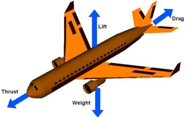
A force may be thought of as a push or pull in a specific direction. A force is a vector quantity so a force has both a magnitude and a direction. When describing forces, we have to specify both the magnitude and the direction. This slide shows the forces that act on an airplane in flight.
Weight:
weight is a force that is always directed toward the center of the earth. The magnitude of the weight depends on the mass of all the airplane parts, plus the amount of fuel, plus any payload on board (people, baggage, freight, etc.). The weight is distributed throughout the airplane. But we can often think of it as collected and acting through a single point called the center of the gravity In flight, the airplane rotates about the center of the gravity.
Flying encompasses two major problems; overcoming the weight of an object by some opposing force, and controlling the object in flight. Both of these problems are related to the object's weight and the location of the center of gravity. During a flight, an airplane's weight constantly changes as the aircraft consumes fuel. The distribution of the weight and the center of gravity also changes. So the pilot must constantly adjust the controls to keep the airplane balanced, or trimmed.
LIFT:
To overcome the weight force, airplanes generate an opposing force called lift. Lift is generated by the motion of the airplane through the air and is an aerodynamic force "Aero" stands for the air, and "dynamic" denotes motion. Lift is directed perpendicular to the flight direction. The magnitude of the lift depends on several factors including the shape, size, and velocity of the aircraft. As with weight, each part of the aircraft contributes to the aircraft lift force. Most of the lift is generated by the wings. Aircraft lift acts through a single point called the center of pressure. The center of pressure is defined just like the center of gravity, but using the pressure distribution around the body instead of the weight distribution.
The distribution of lift around the aircraft is important for solving the control problem. Aerodynamic surfaces are used to control the aircraft in roll, pitch, and yaw.
Drag:
As the airplane moves through the air, there is another aerodynamic force present. The air resists the motion of the aircraft and the resistance force is called drag. Drag is directed along and opposed to the flight direction. Like lift, there are many factors that affect the magnitude of the drag force including the shape of the aircraft, the "stickiness" of the air, and the velocity of the aircraft. Like lift, we collect all of the individual components' drags and combine them into a single aircraft drag magnitude. And like lift, drag acts through the aircraft center of pressure.
Thrust:
To overcome drag, airplanes use a propulsiton system to generate a force called thurst. The direction of the thrust force depends on how the engines are attached to the aircraft. In the figure shown above, Two turbine engines are located under the wings, parallel to the body, with thrust acting along the body centerline. On some aircraft, such as the Harrier, the thrust direction can be varied to help the airplane take off in a very short distance. The magnitude of the thrust depends on many factors associated with the propulsion system including the type of engine, the number of engines, and the thorttle setting.
For jet engines, it is often confusing to remember that aircraft thrust is a reaction to the hot gas rushing out of the nozzle. The hot gas goes out the back, but the thrust pushes towards the front. Action <--> reaction is explained by Newton's third Law of motion.
The motion of the airplane through the air depends on the relative strength and direction of the forces shown above. If the forces are balanced the aircraft cruises at constant velocity. If the forces are Unbalanced the aircraft accelerates in the direction of the largest force.
Tyre design:
An aircraft tire or tyre is designed to withstand extremely heavy loads for short durations. The number of tires required for aircraft increases with the weight of the aircraft, as the weight of the airplane needs to be distributed more evenly. Aircraft tire tread patterns are designed to facilitate stability in high crosswind conditions, to channel water away to prevent hydroplaning, and for braking effect.
A tyre is made from rubberized fabric piles over a rubber liner and the edges of the piles are wrapped around a wire bead, which holdsthe tyre to the wheel rim. The fabric piles are covered with a rubber compound tread and a different rubber compound for the side walls. The tyre is cured in a mould to vulcanize the parts into a single unit and form the tread design.
The tread refers to the wearable part of the tire that is designed to come into contract with the ground. The tread is located on the tire crown and must resist frictional wear, abrasion, cracking and cuts that occur as a result of the landing surface and condition of the runway.
The tread pattern seen on the tire differs according to the operational requirements of the tire. Most tires are grooved in the circumferential direction which provides good operating characteristics for aircraft generally flown into and out of prepared runways. The grooves that characterize a rib tread tire assist in cooling the tire and provide a means for water to channel away from the tire in wet conditions.
Aircraft operating from unprepared or unpaved surfaces may be fitted with a cross-tread pattern. This diamond pattern is cut deep into the tire and provides more traction that the rib tread design in soft ground. On a hard surface (asphalt runway) the tire has a smaller total contact area and so will provide less traction that a tire with a rib tread.
Some older aircraft may have a smooth tread with no ribs or cut-outs. This provides the greatest traction, largest contact area, and subsequently the greatest frictional force which assists in stopping the aircraft.
Rolling resistance:
rolling resistance is defined as the energy consumed by a tire per unit distance covered.[13] It is also called rolling friction or rolling drag. It is one of the forces that act to oppose the motion of a driver.
It is the resistance that the tires offer against motion whileon ground .In case of aircraft rolling resistance can be experienced while take off and while landing. The rolling resistance force is given by the following exression
The "rolling resistance coefficient" is defined by the following equation:
- Frr =µrr + m.g
- m =Mass of aircraft
- µrr=Coefficient of rolling resistance.
Tyre pressure:
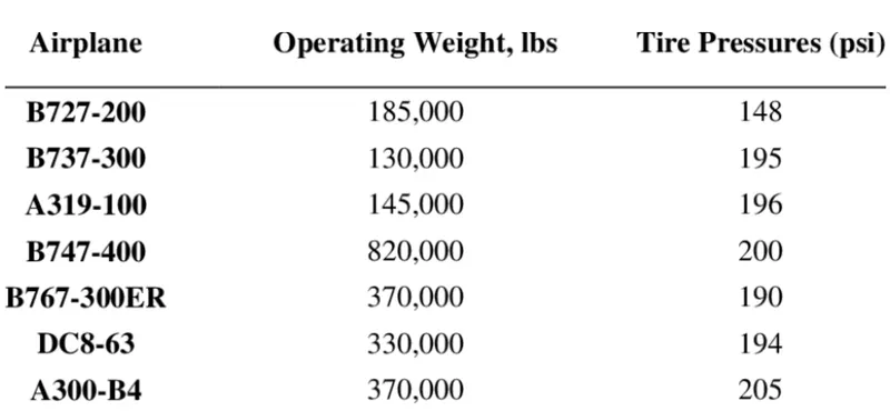
- Aircraft tires operate at such high extremes of pressure, load, and speed, their care and service is critically important. The most important action an operator can take to prevent tire-related events is to maintain proper tire inflation pressure.
- Aircraft tires are usually inflated with nitrogen to minimize expansion and contraction from extreme changes in ambient temperature and pressure experienced during flight.Dry nitrogen expands at the same rate as other dry atmospheric gases (normal air is about 80% nitrogen),but common compression air source may contain moisture,which increases the expansion rate expansion rate with temperature.
- Aircraft tires generally operate at high pressure, up to 200psi(14 bar.1400 kPa) for airliners and even higher for business jets.
Brake forces when landing:
Aircraft brakes stop a moving aircraft by converting its kinetic energy to heat energy by means of friction between rotating and stationary discs located in brake assemblies in the wheels. Brakes provide this critical stopping function during landings to enable airplanes to stop within the length of the runway.
The brake units are powered by the hydraulics system. An electrical signal is sent from the flight deck to hydraulic actuators near the main landing gear.
Here, hydraulic fluid at 3,000 pound per square inch is used to force the brake unit against the wheel, thus slowing it down.
Aircraft braking systems :
Airplanes rely on a braking system to safely land on runways. At cruising altitude, most commercial airplanes fly at a speed of roughly 500 to 600 mph. When landing, however, they must reduce their speed. A typical 747, for instance, has a landing speed of about 160 to 170 mph. And upon touching the runway, airplanes must quickly brake until they come to a complete stop. How do airplanes brake when landing exactly.
WIND SPOILER:
Many airplanes use wing spoilers to assist with braking when landing. Not to be confused with ailerons, spoilers are extendable flaps on the ends of an airplane’s wings. Pilots can raise the spoilers to decelerate the airplane as it approaches the runway. And even while on the runway, pilots will typically leave the wing spoilers raised. Raised wing spoilers create drag, which essentially slows down the airplane so that it’s able to brake more quicklY.
DISC BRAKING:
In addition to wing spoilers, airplanes use disc brakes. Airplane disc brakes are similar to the braking system in automobiles. They consist of a pair of calipers that, when engaged, squeeze pads against the rotors of an airplane’s landing gear.
Disc brakes are designed to remain static at all times. In other words, they don’t rotate with the wheels of an airplane’s landing gear. As the wheels turn, the disc brakes will remain static and stationary. They are a vital component of an airplane’s braking system because they are designed to apply pressure to the airplane’s wheels. Disc brakes will squeeze the wheels, thereby slowing down the speed at which they spin. In turn, this reduces the speed of the airplane so that it can come to a complete stop on the runway.
REVERSE THURST:
Finally, many jet airplanes use reverse thrust to assist with braking during landings. Reverse thrust is a feature in jet engine airplanes that, as the name suggests, involves the reversal of the engines’ thrust. When flying, the thrust is projected out the rear of an airplane’s engines. When landing, however, pilots may use the reverse thrust feature. Reverse thrust changes the direction of the engines’ thrust. Rather than projecting out the rear, the thrust will be projected out the front. This reversal of thrust provides deceleration that allows airplanes to slow down more quickly when landing.
PART B:-
STUDY 1:
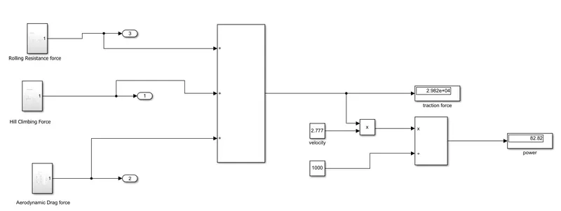
6(A).With necessary assumptions, calculate the force and power required to push / pull an aircraft by a towing vehicle.
Here the pushback truck experience two kinds of force acting on them when they try to push/pull the aircraft.
- Rolling resistance
- Aerodynamic drag force.
Where,
U=coeffcient of rolling resisitance,
m=mass,
g=acceleration due to gravity.
- The rolling force acts on both the pushback truck and the aircraft. So considering the aircraft,
Let's as assume,
Towing Vehicle mass = 50000kg
Aircraft mass = 183700kg
Total mass of the vehicle = (50000+183700)=233700kg
Speed of the vehicle(V) = 10 km/hr=2.77m/s
Rolling resistance force:
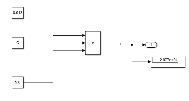
- The formula used of the rolling resistance is Frr= u*m*g
Frr= u*m*g
=0.013. 233700 . 9.8
=29,773.38N
Aerodynamic force:
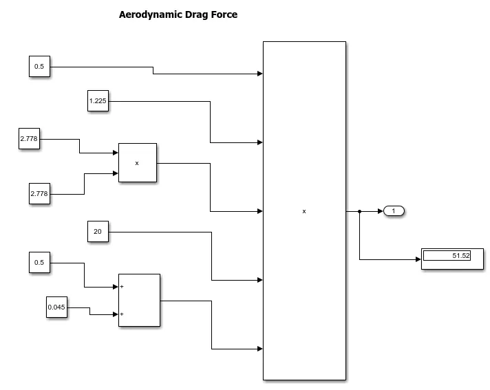
- The aerodynamic force to move an airplane on a absolute flat runway with no wind at constant low speed is usually very negligible Fd=1/2.p.A.Cd.v^2
Where,
p = ai density kg/m^3,
a=front area im m^2
C= drag cofficient
V= velocity is m/s.
Fd=1/2.p.A.Cd.v^2