Project-1: Powertrain for aircraft in runways
Part A:
1. Search and list out the total weight of various types of aircrafts.
2. Is there any difference between ground speed and air speed?
3. Why is it not recommended to use aircraft engine power to move it on the ground at Airport?
4. How an aircraft is pushed to runway when its ready to take off?
5. Learn about take off power, tyre design, rolling resistance, tyre pressure, brake forces when landing.
Part B:
6. A. With necessary assumptions, calculate the force and power required to push / pull an aircraft by a towing vehicle.
B. Develop the model for the calculated force and power using Simulink.
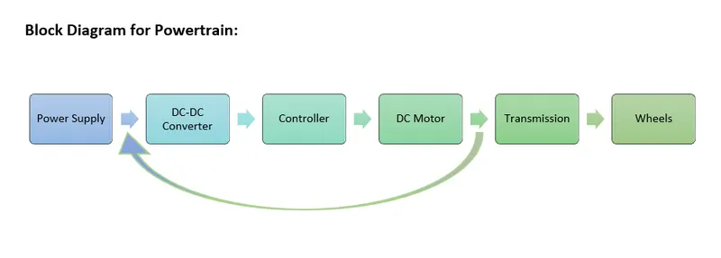
7. A. Design an electric powertrain with type of motor, it’s power rating, and energy requirement to fulfill aircraft towing application in Simulink. Estimate the duty cycle range to control the aircraft speed from zero to highest. Make all required assumptions. Prepare a table of assumed parameters. Draw a block diagram of powertrain.
(Hint :DC7 Block)
B. Also, Design the parameters in excel sheet.
PART A:
1. Search and list out the total weight of various types of aircrafts.
There are many factors that lead to efficient and safe operation of aircraft. Among these vital factors are proper weights and balance control.
The maximum allowable weight for an aircraft is determined by design considerations. The manufacturer provides the aircraft operator with the empty weight of the aircraft and the location of its empty weight centre of gravity (EWCG) at the time the certified aircraft leaves the factory.
However, the maximum operational weight may be less than the maximum allowable weight due to such considerations as high-density altitude or high-drag field conditions caused by wet grass or water on the runway. The maximum operational weight may also be limited by the departure or arrival airport’s runway length.
Manufacturer’s Design Weight Limitation
The maximum allowable weight for an aircraft is determined by design considerations by the aircraft’s manufacturer.
However, the maximum operational weight may be less than the maximum allowable weight due to such considerations as high-density altitude or high-drag field conditions caused by wet grass or water on the runway.
The maximum operational weight may also be limited by the departure or arrival airport’s runway length.
The structural weight limits are based on aircraft maximum structural capability and define the envelope for the CG charts. Aircraft structural weight capability is established during aircraft design and certification.
Maximum Design Taxi Weight (MDTW OR MTW)
The maximum design taxi weight or maximum design ramp weight (MDRW) is the maximum certificated design weight for aircraft ground manoeuvres as limited by aircraft strength and airworthiness requirements.
The difference between the maximum taxi/ramp weight and the maximum take-off weight (maximum taxi fuel allowance) depends on the size of the aircraft, the number of engines, APU operation, and engines/APU fuel consumption, and is typically assumed for 10 to 15 minutes allowance of taxi and run-up operations.
Maximum Design Take-off Weight (MDTOW OR MTOW)
The maximum design take-off weight is the maximum certificated design weight for take-off run as limited by aircraft strength and airworthiness requirements.
Maximum Design Landing Weight (MDLW OR MLW)
The Maximum design landing weight is the maximum certificated design weight for landing limited by aircraft strength and airworthiness requirements. It generally depends on the landing gear strength, or the landing impact loads on certain parts of the wing structure.
MDLW < MDTOW < MDTW
Maximum Design Zero-Fuel Weight (MDZFW)
The maximum design zero-fuel weight is the maximum certificated design weight of the aircraft less all usable fuel and other specified usable agents as limited by aircraft strength and airworthiness requirements.
It is the maximum weight permitted before usable fuel and other specified usable fluids are loaded in specified sections of the airplane.
The weight difference between the MDTOW and the MDZFW may be utilized only for the addition of fuel.
Maximum payload = MDZFW – OEW
Minimum Flight Weight (MFW)
Minimum certificated weight for flight as limited by aircraft strength and airworthiness requirements.
EFFECTS OF WEIGHT
- Some of the problems caused by overloading an aircraft are:
- The aircraft will need a higher take-off speed, which results in a longer take-off run.
- Both the rate and angle of climb will be reduced.
- The service ceiling will be lowered.
- The cruising speed will be reduced.
- The cruising range will be shortened.
- Manoeuvrability will be decreased.
- A longer landing roll will be required because the landing speed will be higher.
- Excessive loads will be imposed on the structure, especially the landing gear.
AIRCRAFT GROSS WEIGHT
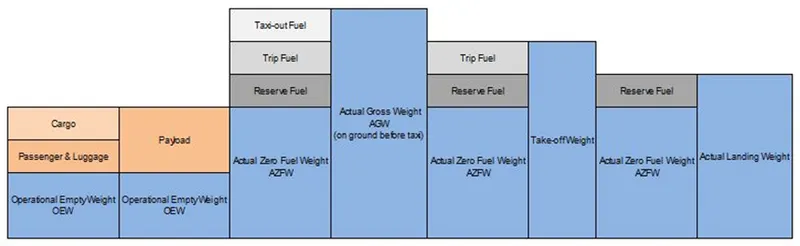
The aircraft gross weight is the total aircraft weight at any moment during the flight or ground operation.
The aircraft gross weight decreases during flight due to fuel and oil consumption. The aircraft gross weight may also vary during flight due to payload dropping or in-flight refuelling.
Manufacturer’s Empty Weight (MEW)
Let’s start with the aircraft itself. An aircraft “as is” includes:
- Airframe structure with all moving mechanical parts (fuselage, wings, flaps, gear, rudder, nacelle …)
- Power generation system (APU, main engines, power plant…)
- Systems (electrical, hydraulics, pneumatic, fuel flow system, instrument, navigation, air conditioning, anti-ice, fixed furnishing)
- Fixed equipment and services considered an integral part of the aircraft
- Fixed ballast
- Closed system fluids
- Unused fuel only for small aircraft
- All these items above form the Manufacturer’s Empty Weight (MEW).
- This weight does not include:
- Fuel
- Oil, potable water
- Payload (Cargo, passenger, luggage)
- Removable equipment
- Customer specific installations or operator items
Operational Empty Weight (OEW) :
The MEW and the operator’s items are summed up to the Operational Empty Weight (OEW). The OEW is usually fixed for a specific aircraft and only gets changed during maintenance or operational changes

OEW is the empty weight that is used in the flight simulator or the usual planning software.
The operator’s items are:
fluids necessary for aircraft operation (engine oil and coolant, water, unusable fuel)
- The water for galleys and lavatories
- Aircraft documentation
- Passenger seats (and the life vests)
- galley structure
- catering emergency equipment
- Aircraft crew and their luggage.
- Standard items necessary for full operation
Actual Zero Fuel Weight (AZFW)
If we add the payload to the empty plane weight, we get the Actual Zero Fuel Weight (AZFW).

The payload includes:
- the passenger’s weight (the standard weights used defined by ICAO respectively)
- the passenger’s luggage’s weight
- the cargo weights

The assumed weights vary around some kg / lbs. depending on the number of seats available on the aircraft.
- a male passenger (incl. cabin luggage) weighs around 82kg (181 lbs.)
- a female passenger around 67kg (148 lbs.)
- a child around 50kg (110lbs.)
- an infant 16kg (35 lbs.).
These are statistical values but otherwise one would need to weigh every single passenger during check in to get his exact weight. Additional payload consists of baggage and cargo (such as mail or goods).
Actual Gross Weight (AGW)
In addition to the actual zero fuel weight, we add the fuel required for the flight and we get the Actual Gross Weight (AGW).
|
type |
1 Litre |
1 U.S. Gallon |
1 Imp. Gallon |
|
Aviation Gas |
1.58 lb. |
6.0 lb. |
7.20 lb. |
|
JP-4 |
1.76 lb. |
6.6 lb. |
8.01 lb. |
|
Kerosene |
1.85 lb. |
7.0 lb. |
8.39 lb. |
|
Oil |
1.95 lb. |
7.5 lb. |
8.5 lb. |

At that time, you should have calculated your total fuel for this flight.
The actual gross weight is the weight of aircraft ready for departure at the gate before push-back and start-up.
Note: 1kg = 2.20462262185 lb(s)
The total fuel shall include:
- Taxi-out fuel (at departure airfield)
- Trip fuel
- Holding
- Re-routing expectation
- regulation needs depending on your route arrival airfield
- fuel to join alternate airfield
- taxi-in fuel at destination,
- final reserve
Take-Off Weight
Fuel burn during taxi operation to the departure runway reduces the gross weight. At the holding point, we have the Actual Take-off Weight (ATOW) which is used for take-off performance calculation.
The gross weight varies during flight. Fuel and oil consumption reduces the gross weight. Additionally, it may vary during flight due to inflight refuelling or payload dropping.

Maximum Design Take-off Weight (MDTOW)
The maximum take-off weight (also known as the maximum brake-release weight) is the maximum weight authorized at brake release for take-off, or at the start of the take-off roll.
The maximum take-off weight is always less than the maximum taxi/ramp weight to allow for fuel burned during taxi by the engines and the APU.
In operation, the maximum weight for take-off may be limited to values less than the maximum take-off weight due to aircraft performance, environmental conditions, airfield characteristics (take-off field length, altitude), maximum tire speed and brake
At this weight, the subsequent addition of fuel will not result in the aircraft design strength being exceeded. The weight difference between the MTOW and the MZFW may be utilized only for the addition of fuel.
LANDING WEIGHT :
With the calculation of fuel consumption during flight, we can calculate the Estimated Landing Weight (ELW) which is used for landing performance calculation at the destination.
Approaching your destination, you use your current gross weight to determine the final approach speed. The gross weight now is the Actual Landing Weight (ALW).

Of course, before landing, you never land without any fuel in reserve. The regulation is strict about fuel calculation for commercial air transportation including reserve fuel. Except in specific situations like re-routing, multiple holding, landing at alternate or technical problems, at landing, the aircraft shall still have the expected reserve fuel if there was no extra consumption.

GRAPHICAL SUMMARY OF OPERATIONAL WEIGHT :
|
Type |
MTOW [kg] |
MLW [tonnes] |
TOR [m] |
LR [m] |
ICAO category |
FAA category |
|
Antonov An-225 |
640,000 |
591.7 |
3500 |
Heavy |
Super |
|
|
Scaled Composites Model 351 Stratolaunch |
589,670 |
3660 |
Heavy |
Super |
||
|
Airbus A380-800 |
575,000 |
394 |
3100 |
1930 |
Super |
Super |
|
Boeing 747-8F |
447,700 |
346.091 |
3100 |
1800 |
Heavy |
Heavy |
|
Boeing 747-8 |
443,613 |
306.175 |
3100 |
Heavy |
Heavy |
|
|
Boeing 747-400ER |
412,770 |
295.742 |
3090 |
Heavy |
Heavy |
|
|
Antonov An-124-100M |
405,060 |
330 |
2520 |
900 |
Heavy |
Heavy |
|
Boeing 747-400 |
396,900 |
295.742 |
3018 |
2179 |
Heavy |
Heavy |
|
Lockheed C-5 Galaxy |
381,000 |
288.417 |
2530 |
1494 |
Heavy |
Heavy |
|
Boeing 747-200 |
377,840 |
285.700 |
3338 |
2109 |
Heavy |
Heavy |
|
Boeing 747-300 |
377,840 |
260.320 |
3222 |
1905 |
Heavy |
Heavy |
|
Airbus A340-500 |
371,950 |
240 |
3050 |
2010 |
Heavy |
Heavy |
|
Airbus A340-600 |
367,400 |
256 |
3100 |
2100 |
Heavy |
Heavy |
|
Boeing 777F |
347,800 |
260.816 |
2830 |
Heavy |
Heavy |
|
|
Airbus A330-900 |
352,000 |
251.5 |
3100 |
Heavy |
Heavy |
|
|
Boeing 777-300ER |
351,800 |
251.29 |
3100 |
Heavy |
Heavy |
|
|
Boeing 777-200LR |
347,450 |
223.168 |
3000 |
Heavy |
Heavy |
|
|
Boeing 747-100 |
340,200 |
265.300 |
Heavy |
Heavy |
||
|
Airbus A350-1000 |
308,000 |
233.5 |
Heavy |
Heavy |
||
|
Boeing 777-300 |
299,370 |
237.683 |
3380 |
Heavy |
Heavy |
|
|
Boeing 777-200ER |
297,550 |
213.00 |
3380 |
1550 |
Heavy |
Heavy |
|
Airbus A340-300 |
276,700 |
190 |
3000 |
1926 |
Heavy |
Heavy |
|
McDonnell Douglas MD-11 |
273,300 |
185 |
2990 |
1890 |
Heavy |
Heavy |
|
Airbus A350-900 |
270,000 |
175 |
2670 |
1860 |
Heavy |
Heavy |
|
Ilyushin Il-96M |
270,000 |
195.04 |
3115 |
2118 |
Heavy |
Heavy |
|
McDonnell Douglas DC-10 |
256,280 |
183 |
2990 |
1890 |
Heavy |
Heavy |
|
Boeing 787-9 |
254,000 |
192.777 |
2900 |
Heavy |
Heavy |
|
|
Boeing 787-10 |
254,000 |
201.849 |
Heavy |
Heavy |
||
|
Airbus A340-200 |
253,500 |
181 |
2990 |
Heavy |
Heavy |
|
|
Ilyushin IL-96-300 |
250,000 |
175 |
2600 |
1980 |
Heavy |
Heavy |
|
Airbus A330-300 |
242,000 |
185 |
2500 |
1750 |
Heavy |
Heavy |
|
Airbus A330-200 |
242,000 |
180 |
2220 |
1750 |
Heavy |
Heavy |
|
Lockheed L-1011-500 |
231,300 |
166.92 |
2636 |
Heavy |
Heavy |
|
|
Boeing 787-8 |
228,000 |
172.365 |
3300 |
1695 |
Heavy |
Heavy |
|
Lockheed L-1011-200 |
211,400 |
Heavy |
Heavy |
|||
|
Ilyushin IL-86 |
208,000 |
175 |
Heavy |
Heavy |
||
|
Boeing 767-400ER |
204,000 |
158.758 |
3414 |
Heavy |
Heavy |
|
|
Airbus A300-600R |
192,000 |
140 |
2385 |
1555 |
Heavy |
Heavy |
|
Boeing 767-300ER |
187,000 |
136.08 |
2713 |
1676 |
Heavy |
Heavy |
|
Concorde |
185,000 |
111.1 |
3440 |
2220 |
Heavy |
Heavy |
|
Airbus A300-600 |
163,000 |
138 |
2324 |
1536 |
Heavy |
Heavy |
|
Boeing 767-300 |
159,000 |
136.078 |
2713 |
1676 |
Heavy |
Heavy |
|
Airbus A310-300 |
157,000 |
124 |
2290 |
1490 |
Heavy |
Heavy |
|
Vickers VC10 |
152,000 |
151.9 |
Heavy |
Heavy |
||
|
Boeing 707-320B |
151,000 |
97.5 |
Heavy |
Heavy |
||
|
Boeing 707-320C |
151,000 |
112.1 |
Heavy |
Heavy |
||
|
Douglas DC-8-61 |
147,000 |
Heavy |
Heavy |
|||
|
Airbus A310-200 |
142,000 |
123 |
1860 |
1480 |
Heavy |
Heavy |
|
Airbus A400M |
141,000 |
122 |
980 |
770 |
Heavy |
Heavy |
|
Douglas DC-8-32 |
140,000 |
Heavy |
Heavy |
|||
|
Douglas DC-8-51 |
125,000 |
Medium |
Large |
|||
|
Boeing 757-300 |
124,000 |
101.6 |
2550 |
1750 |
Medium |
Large |
|
Boeing 707-120B |
117,000 |
86.3 |
Medium |
Large |
||
|
Boeing 757-200 |
116,000 |
89.9 |
2347 |
1555 |
Medium |
Large |
|
Boeing 720B |
106,000 |
79.5 |
Medium |
Large |
||
|
Boeing 720 |
104,000 |
79.5 |
Medium |
Large |
||
|
Tupolev Tu-154M |
104,000 |
80 |
Medium |
Large |
||
|
Tupolev Tu-204SM |
104,000 |
87.5 |
2250 |
Medium |
Large |
|
|
Convair 880 |
87,500 |
Medium |
Large |
|||
|
Boeing 737-900 |
85,000 |
66.36 |
2500 |
1704 |
Medium |
Large |
|
Boeing 737-900ER |
85,000 |
71.35 |
2804 |
1829 |
Medium |
Large |
|
Boeing 727-200 Advanced |
84,000 |
70.1 |
Medium |
Large |
||
|
Airbus A321-100 |
83,000 |
77.8 |
2200 |
1540 |
Medium |
Large |
|
Boeing 737-800 |
79,000 |
65.32 |
2308 |
1634 |
Medium |
Large |
|
Boeing 727-200 |
78,000 |
68.1 |
Medium |
Large |
||
|
McDonnell-Douglas MD-83 |
73,000 |
63.28 |
Medium |
Large |
||
|
Boeing 727-100 |
72,500 |
62.4 |
Medium |
Large |
||
|
Boeing 727-100C[17] |
72,500 |
62.4 |
Medium |
Large |
||
|
McDonnell-Douglas MD-90-30 |
71,000 |
64.41 |
2165 |
1520 |
Medium |
Large |
|
de Havilland Comet 4 |
70,700 |
Medium |
Large |
|||
|
Boeing 737-700 |
70,000 |
58.06 |
1921 |
1415 |
Medium |
Large |
|
Airbus A320-100 |
68,000 |
66 |
1955 |
1490 |
Medium |
Large |
|
Boeing 737-400 |
68,000 |
54.9 |
2540 |
1540 |
Medium |
Large |
|
de Havilland Comet 3 |
68,000 |
Medium |
Large |
|||
|
Boeing 377 |
67,000 |
Medium |
Large |
|||
|
Boeing 737-600 |
66,000 |
54.66 |
1796 |
1340 |
Medium |
Large |
|
Airbus A220-300 |
65,000 |
57.61 |
1890 |
1494 |
Medium |
Large |
|
Hawker Siddeley Trident 2E |
65,000 |
Medium |
Large |
|||
|
Airbus A319 |
64,000 |
62.5 |
1850 |
1470 |
Medium |
Large |
|
Boeing 737-300 |
63,000 |
51.7 |
1939 |
1396 |
Medium |
Large |
|
Boeing 737-500 |
60,000 |
49.9 |
1832 |
1360 |
Medium |
Large |
|
Airbus A220-100 |
59,000 |
50.80 |
1463 |
1356 |
Medium |
Large |
|
Airbus A318 |
59,000 |
57.5 |
1375 |
1340 |
Medium |
Large |
|
Boeing 717-200HGW |
55,000 |
47.174 |
1950 |
Medium |
Large |
|
|
Douglas DC-7 |
55,000 |
Medium |
Large |
|||
|
de Havilland Comet 2 |
54,000 |
Medium |
Large |
|||
|
Boeing 717-200BGW |
50,000 |
46.265 |
1950 |
Medium |
Large |
|
|
de Havilland Comet 1 |
50,000 |
Medium |
Large |
|||
|
Douglas DC-6A |
48,600 |
Medium |
Large |
|||
|
Douglas DC-6B |
48,500 |
Medium |
Large |
|||
|
Embraer 190 |
48,000 |
43 |
2056 |
1323 |
Medium |
Large |
|
Caravelle III |
46,000 |
Medium |
Large |
|||
|
Fokker 100 |
46,000 |
39.95 |
1621 |
1350 |
Medium |
Large |
|
Douglas DC-6 |
44,000 |
Medium |
Large |
|||
|
Avro RJ-85 |
42,000 |
36.74 |
Medium |
Large |
||
|
Handley Page Hermes |
39,000 |
Medium |
Large |
|||
|
Embraer 175 |
37,500 |
32.8 |
2244 |
1304 |
Medium |
Large |
|
Bombardier CRJ900 |
36,500 |
33.345 |
1778 |
1596 |
Medium |
Large |
|
Embraer 170 |
36,000 |
32.8 |
1644 |
1274 |
Medium |
Large |
|
Bombardier CRJ700 |
33,000 |
30.39 |
1564 |
1478 |
Medium |
Large |
|
Douglas DC-4 |
33,000 |
Medium |
Large |
|||
|
Vickers Viscount 800 |
30,400 |
Medium |
Large |
|||
|
Bombardier Q400 |
28,000 |
28.01 |
1219 |
1295 |
Medium |
Large |
|
Bombardier CRJ200 |
23,000 |
21.319 |
1918 |
1479 |
Medium |
Large |
|
ATR 72-600 |
22,800 |
22.35 |
1333 |
914 |
Medium |
Large |
|
Saab 2000 |
22,800 |
21.5 |
1300 |
Medium |
Large |
|
|
Embraer ERJ 145 |
22,000 |
19.3 |
2270 |
1380 |
Medium |
Large |
|
ATR 42-500 |
18,600 |
18.3 |
1165 |
1126 |
Medium |
Small |
|
Saab 340 |
13,150 |
12.930 |
1300 |
1030 |
Medium |
Small |
|
Embraer 120 Brasilia |
11,500 |
11.25 |
1560 |
1380 |
Medium |
Small |
|
BAe Jetstream 41 |
10,890 |
10.570 |
1493 |
826 |
Medium |
Small |
|
Learjet 75 |
9,752 |
8.709 |
1353 |
811 |
Medium |
Small |
|
Pilatus PC-24 |
8,300 |
7.665 |
893 |
724 |
Medium |
Small |
|
Embraer Phenom 300 |
8,150 |
7.65 |
956 |
677 |
Medium |
Small |
|
Beechcraft 1900D |
7,765 |
7.605 |
1036 |
853 |
Medium |
Small |
|
Cessna Citation CJ4 |
7,761 |
7.103 |
1039 |
896 |
Medium |
Small |
|
de Havilland Hercules |
7,000 |
Medium |
Small |
|||
|
Embraer Phenom 100 |
4,800 |
4.43 |
975 |
741 |
Light |
Small |
2.Is there any difference between ground speed and air speed?
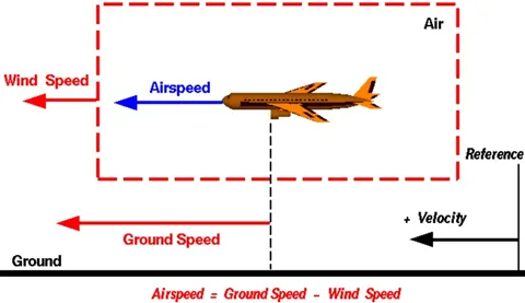
One of the most confusing concepts for young scientists is the relative velocity between objects. Aerodynamic forces are generated by an object moving through a fluid (liquid or gas). A fixed object in a static fluid does not generate aerodynamic forces. Hot air balloons "lift" because of buoyancy forces and some aircraft like the Harrier use thrust to "lift" the vehicle, but these are not examples of aerodynamic lift. To generate lift, an object must move through the air, or air must move past the object. Aerodynamic lift depends on the square of the velocity between the object and the air. Now things get confusing because not only can the object be moved through the air, but the air itself can move. To properly define the relative velocity, it is necessary to pick a fixed reference point and measure velocities relative to the fixed point. In this slide, the reference point is fixed to the ground, but it could just as easily be fixed to the aircraft itself. It is important to understand the relationships of wind speed to ground speed and airspeed
Wind Speed
For a reference point picked on the ground, the air moves relative to the reference point at the wind speed. Notice that the wind speed is a vector quantity and has both a magnitude and a direction. Direction is important. A 20-mph wind from the west is different from a 20-mph wind from the east. The wind has components in all three primary directions (north-south, east-west, and up-down). In this figure, we are considering only velocities along the aircraft's flight path. A positive velocity is defined to be in the direction of the aircraft's motion. We are neglecting cross winds, which occur perpendicular to the flight path but parallel to the ground, and updrafts and downdrafts, which occur perpendicular to the ground.
Ground Speed
For a reference point picked on the ground, the aircraft moves relative to the reference point at the ground speed. Ground speed is also a vector quantity so a comparison of the ground speed to the wind speed must be done according to rules for vector comparisons.
Air Speed
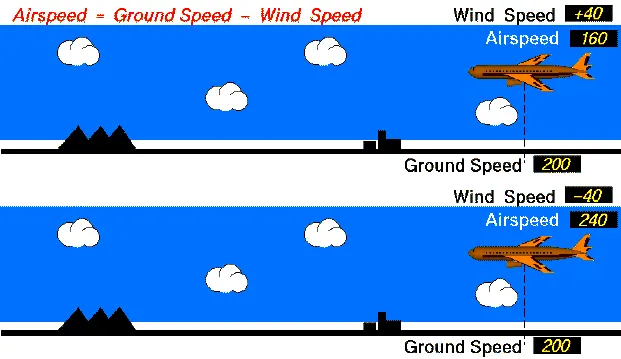
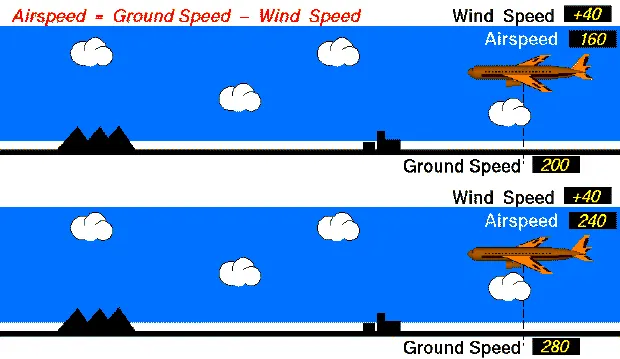
The important quantity in the generation of lift is the relative velocity between the object and the air, which is called the airspeed. Airspeed cannot be directly measured from a ground position but must be computed from the ground speed and the wind speed. Airspeed is the vector difference between the ground speed and the wind speed.
Airspeed = Ground Speed - Wind Speed
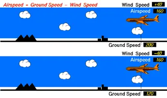
At equal air speed :
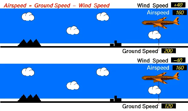
On a perfectly still day, the airspeed is equal to the ground speed. But if the wind is blowing in the same direction that the aircraft is moving, the airspeed will be less than the ground speed
At Equal Wind Speed:
During Plane Take Off :
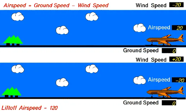
Significance of Understanding Relative Velocity :
The importance of the relative velocity explains why airplanes take off and land on different runways on different days. Airplanes always try to take off and land into the wind. This requires a lower ground speed to become airborne, which means the plane can take off or land in the shortest distance travelled along the ground. Since runways have a fixed length, you want to get airborne as fast as possible on take-off and stopped as soon as possible on landing. In the old days, a large "windsock" was hung near the runway for pilots to see which way the wind was blowing to adjust their take-off and landing directions. Now mechanical or electronic devices provide the information that is radioed to the cockpit.
The relationship between airspeed, wind speed, and ground speed explains why wind tunnel testing is possible and how kites fly.
In the wind tunnel, the ground speed is zero because the model is fixed to the walls of the tunnel. The airspeed is then the negative of the wind speed that is generated in the tunnel. Whether the object moves through the air, or the air moves over the object, the forces are the same.
A kite usually has no ground speed because a kite is held on the end of a string. But the kite still has an airspeed that is equal to the wind speed. You can fly a kite only with the wind at your back.
3.Why is it not recommended to use aircraft engine power to move it on the ground at Airport?
All jet engines, which are also called gas turbines, work on the same principle. The engine sucks air in at the front with a fan. A compressor raises the pressure of the air. The compressor is made with many blades attached to a shaft. The blades spin at high speed and compress or squeeze the air. The compressed air is then sprayed with fuel and an electric spark lights the mixture. The burning gases expand and blast out through the nozzle, at the back of the engine. As the jets of gas shoot backward, the engine and the aircraft are thrust forward. As the hot air is going to the nozzle, it passes through another group of blades called the turbine. The turbine is attached to the same shaft as the compressor. Spinning the turbine causes the compressor to spin.
The air goes through the core of the engine as well as around the core. This causes some of the air to be very hot and some to be cooler. The cooler air then mixes with the hot air at the engine exit area
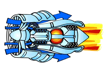
Thrust is the forward force that pushes the engine and, therefore, the airplane forward. According to Newton’s Third Law, " For every action there is an equal and opposite reaction ”.
The principle of operation of the Jet engine is,
- The engine takes in a large volume of air.
- The air is heated and compressed and slowed down.
- The air is forced through many spinning blades.
- By mixing this air with jet fuel, the temperature of the air can be as high as three thousand degrees.
- The power of the air is used to turn the turbine.
- Finally, when the air leaves, it pushes backward out of the engine. This causes the plane to move forward.
Parts of a Jet Engine :
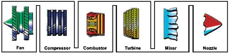
- Fan:
- The fan is the first component in a turbo-fan.
- The large spinning fan sucks in large quantities of air.
- Most blades of the fan are made of titanium.
- It then speeds this air up and splits it into two parts.
- One part continues through the "core" or centre of the engine, where it is acted upon by the other engine components.
The second part "bypasses" the core of the engine. It goes through a duct that surrounds the core to the back of the engine where it produces much of the force that propels the airplane forward. This cooler air helps to quiet the engine as well as adding thrust to the engine.
Compressor:
The compressor is the first component in the engine core.
The compressor is made up of fans with many blades and attached to a shaft.
The compressor squeezes the air that enters it into progressively smaller areas, resulting in an increase in the air pressure.
This results in an increase in the energy potential of the air.
The squashed air is forced into the combustion chamber.
Combustor:
In the combustor the air is mixed with fuel and then ignited.
There are as many as 20 nozzles to spray fuel into the airstream.
The mixture of air and fuel catches fire.
This provides a high temperature, high-energy airflow.
The fuel burns with the oxygen in the compressed air, producing hot expanding gases.
The inside of the combustor is often made of ceramic materials to provide a heat-resistant chamber. The heat can reach 2700°.
Turbine:
The high-energy airflow coming out of the combustor goes into the turbine, causing the turbine blades to rotate.
The turbines are linked by a shaft to turn the blades in the compressor and to spin the intake fan at the front.
This rotation takes some energy from the high-energy flow that is used to drive the fan and the compressor.
The gases produced in the combustion chamber move through the turbine and spin its blades.
The turbines of the jet spin around thousands of times.
They are fixed on shafts which have several sets of ball-bearing in between them.
Nozzle:
The nozzle is the exhaust duct of the engine.
This is the engine part which produces the thrust for the plane.
The energy depleted airflow that passed the turbine, in addition to the colder air that bypassed the engine core, produces a force when exiting the nozzle that acts to propel the engine, and therefore the airplane, forward.
The combination of the hot air and cold air are expelled and produce an exhaust, which causes a forward thrust.
The nozzle may be preceded by a mixer, which combines the high temperature air coming from the engine core with the lower temperature air that was bypassed in the fan.
The mixer helps to make the engine quieter.
It is not recommended to use aircraft engine power to move it on the ground, but it is still possible to move the aircraft on ground through the process called Taxiing.
Taxiing is the movement of an aircraft on the ground, under its own power, in contrast to towing or pushback where the aircraft is moved by a tug.
The aircraft usually moves on wheels, but the term also includes aircraft with skis or floats (for water-based travel).
When taxiing, aircraft travel slowly. This ensures that they can be stopped quickly and do not risk wheel damage on larger aircraft if they accidentally turn off the paved surface. Taxi speeds are typically 30 to 35 km/h (16 to 19 kts).
Aircraft Engine power to move it on the ground is not recommended to use because,
Use of engine thrust near terminals is restricted due to the possibility of jet blast damage
Thrusting the Jet engine produces lot of noise and fumes plus they burn a lot of fuel.
Fuel Costing is very expensive
not every ground crew is certified to start or taxi the aircraft.
4. How is an aircraft pushed to runway when its ready to take off?
The Procedure in which the aircraft is pushed to runaway when its ready to take off is called Push-Back.
The International Air Transport Association (IATA) defines aircraft pushback as "rearward moving of an aircraft from a parking position to a taxi position by use of specialized ground support equipment.
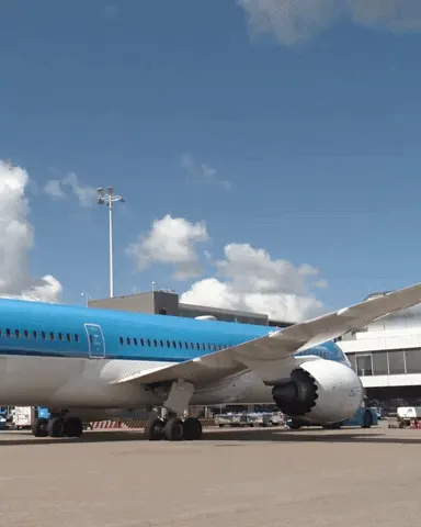
Push-Back:
In aviation, pushback is an airport procedure during which an aircraft is pushed backwards away from its parking position, usually at an airport gate by external power. Pushbacks are carried out by special, low-profile vehicles called pushback tractors or tugs.
Although many aircraft can move themselves backwards on the ground using reverse thrust (a procedure referred to as a power back), the resulting jet blast or prop wash would cause increased noise, damage to the terminal building or equipment, and hurt airport staff due to high-speed debris. This debris would also be sucked into the engine, as it is in normal use, and cause excessive wear - a major cause of wear on aircraft engines is during ground use. A pushback is therefore the preferred method when ground-handling aircraft.
Procedure:
- Pushbacks at busy aerodromesare usually subject to ground control clearance to facilitate ground movement on taxiways.
- Once clearance is obtained, the pilot will communicate with the tractor driver (or a ground handler walking alongside the aircraft in some cases) to start the pushback.
- To communicate, a headsetmay be connected near the nose gear.
- Since the pilots cannot see what is behind the aircraft, steering is done by the pushback tractor driver and not by the pilots.
- Depending on the aircraft type and airline procedure, a bypass pinmay be temporarily installed into the nose gear to disconnect it from the aircraft's normal steering mechanism.
- Once the pushback is completed, the towbar is disconnected, and any bypass pin removed.
- The ground handler will show the bypass pin to the pilots to make it clear that it has been removed.
The pushback is then complete, and the aircraft can taxi forward under its own power
5. Learn about take-off power, tyre design, rolling resistance, tyre pressure, brake forces when landing.
- Take-Off Power:
It is defined as the amount of power that an engine is allowed to produce for a limited period for take-off.- Theuseof takeoff power is usually limited to 5 min for reciprocating engines and up to 2½ min for gas turbine
- Thismaynot always be the case because, with respect to reciprocating engines, it is the brake horsepower developed under standard sea-level conditions and under the maximum conditions of the crankshaft rotational speed and the engine manifold pressure approved for the normal take-off.
- It is limited in continuous use to the period shown in theapprovedengine
- Withrespectto gas turbine engines, it is the thrust developed under static conditions at a specified altitude and atmospheric conditions of the rotor shaft rotational speed and gas temperature approved for the normal take-off.
- It is limitedin continuoususe to the period shown in the approved engine
- Tyre Design:
An aircraft tyre is designed to withstand extremely heavy loads while landing, take off, taxing, and parking. The number of wheels required for aircraft increases with the weight of the aircraft, as the weight of the aeroplane needs to be distributed more evenly.
Design and Construction of Aircraft tyre
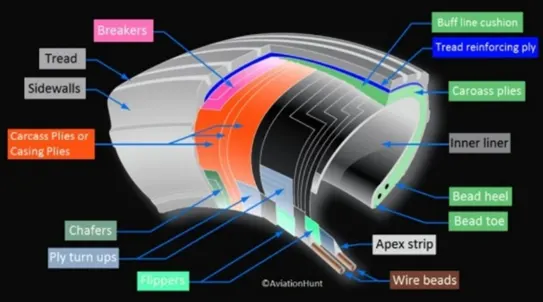
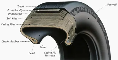
Carcass plies are used to form the tire. They are sometimes called casing plies. An aircraft tyre is constructed for the purpose it serves.
- They support the weight of an aircraft while it is on the ground.
- It also provides the necessary traction for braking and stopping of an aeroplane.
- Tyre also helps to absorb the shock of landing and provide cushioning the roughness of take-off, roll-out, and taxi operations.
Unlike an automobile or truck tyre, it does not have to carry a load for a long period of continuous operation. However, an aircraft tyre absorbs the high impact loads of landing, and, it’s operating at high speeds for a short time when required
Rolling Resistance:
When taking off from a runway covered with slush, standing water or snow, the required take-off ground-run distance will be longer than on a dry runway. This is the result of the fact that slush, standing water and snow on the runway will generate a rolling resistance that increases the total resistance on the aircraft during the ground-run
- Tyre Pressure:
The typical airliner tire can handle a 38-ton load. It can meet the ground 500 times before needing a re-tread, a refresh it can take on seven times in its life.
- A Boeing 777 uses 14 tires, Airbus' A380 carries 22, and the enormous Antonov An-225 demands 32.
- The key to their remarkable durability is maximizing the air pressure.
- The high-flying rubber is typically inflated to 200 psi, roughly six times what you put in an automobile tire, and the tires on an F-16 fighter are pumped to 320 psi.
- It's the pressurized air that is helping the tires to be strong.
The tires themselves aren't terribly large--- a Boeing 737 have a tyre size of rubber 27 inches in diameter, 7.75 inches wide, and wrapped around a 15-inch wheel (27x7.75 R15). - They're typically made of nylon, and more recently a variety known as aramid.
- Each layer of the casing contributes to its load bearing and air pressure resisting capabilities.
- Of course, tires can fail, especially when under-inflated or overloaded. Treads can come off and casings can blow out.
Brake Forces when Landing:
Airplanes rely on a braking system to safely land on runways. At cruising altitude, most commercial airplanes fly at a speed of roughly 500 to 600 mph. When landing, however, they must reduce their speed. A typical 747, for instance, has a landing speed of about 160 to 170 mph. And upon touching the runway, airplanes must quickly brake until they come to a complete stop. This is achieved by
Wing Spoilers:
Many airplanes use wing spoilers to assist with braking when landing. Not to be confused with ailerons, spoilers are extendable flaps on the ends of an airplane’s wings.
Pilots can raise the spoilers to decelerate the airplane as it approaches the runway.
While on the runway, pilots will typically leave the wing spoilers raised.
Raised wing spoilers create drag, which essentially slows down the airplane so that it’s able to brake more quickly.
Disc Brakes:
In addition to wing spoilers, airplanes use disc brakes. Airplane disc brakes are like the braking system in automobiles. They consist of a pair of callipers that, when engaged, squeeze pads against the rotors of an airplane’s landing gear.
Disc brakes are designed to always remain static. In other words, they don’t rotate with the wheels of an airplane’s landing gear.
As the wheels turn, the disc brakes will remain static and stationary.
They are a vital component of an airplane’s braking system because they are designed to apply pressure to the airplane’s wheels.
Disc brakes will squeeze the wheels, thereby slowing down the speed at which they spin.
In turn, this reduces the speed of the airplane so that it can come to a complete stop on the runway.
Reverse Thrust:
Finally, many jet airplanes use reverse thrust to assist with braking during landings. Reverse thrust is a feature in jet engine airplanes that, as the name suggests, involves the reversal of the engines’ thrust. When flying, the thrust is projected out the rear of an airplane’s engines.
When landing, however, pilots may use the reverse thrust feature.
Reverse thrust changes the direction of the engines’ thrust.
Rather than projecting out the rear, the thrust will be projected out the front.
This reversal of thrust provides deceleration that allows airplanes to slow down more quickly when landing.
Part B:
- With necessary assumptions, calculate the force and power required to push / pull an aircraft by a towing vehicle.
- Develop the model for the calculated force and power using Simulink.
To calculate the force and power required to push / pull an aircraft by a towing vehicle, let’s assume the following parameters.
Here we consider the Aircraft to be towed as Airbus A320-100 with MTOW = 68,000 Kg and Towing Vehicle with GVM = 5,000 Kg. Also, for this calculation, we neglect the effect of hill climbing since the plane is flat moving at a velocity of 15 Kmph. Thus, we will have to calculate the total Force from Rolling Resistance and Aerodynamic Force.
Assume,
For, Airbus A320-100 :
GVM = 68,000 Kg
μrr = 0.008
Height = 11m
Width = 10 m (without wings)
Frontal Area = 110 m2
Cd = 0.032
For, Towing Vehicle,
GVM = 5,000 Kg
μrr = 0.01
Height = 5 m
Width = 10 m (without wings)
Frontal Area = 50 m2
Cd = 0.025
|
To calculate force & power required to push / pull an aircraft by a towing vehicle. |
||||
|
PARAMETER |
Aircraft |
Tow Vehicle |
||
|
Rolling Resistance Calculation |
68000.00 |
5000.00 |
||
|
Coefficient of Rolling Resistance |
0.008 |
0.01 |
||
|
Total Mass (Kg) |
68000.00 |
5000.00 |
||
|
Rolling Resistance Force (N) |
5336.64 |
490.50 |
||
|
Total Rolling Resistance Force (N) = Aircraft's Rolling Resistance Force + Tow vehicle's Rolling Resistance Force |
5827.14 |
|||
|
Air Drag Calculation |
|
|||
|
Air Density (Kg/m3) |
1.25 |
1.25 |
||
|
Width (m) |
11.00 |
5.00 |
||
|
Height (m) |
10.00 |
8.00 |
||
|
Drag Coefficient |
0.03 |
0.03 |
||
|
Speed (Kmph) |
15.00 |
15.00 |
||
|
Frontal Area (m2) |
110.00 |
40.00 |
||
|
Speed in m/s |
4.17 |
4.17 |
||
|
Air Drag Force (N) |
38.19 |
10.85 |
||
|
Total Air Drag Force (N) = Aircraft's Air Drag Force + Tow vehicle's Air Drag Force Force |
49.05 |
|||
|
Tractive Force exerted (N) = Air Drag Force + Rolling Resistance Force |
5374.83 |
501.35 |
||
|
Total Tractive Force exerted on Tow vehicle (N) = Total Air Drag Force + Total Rolling Resistance Force |
5876.19 |
|||
|
Total Power at given speed (kW) |
22.40 |
2.09 |
||
|
Total Power required for Push/Pull at given speed (kW) |
24.48 |
|||
Simulink Model :
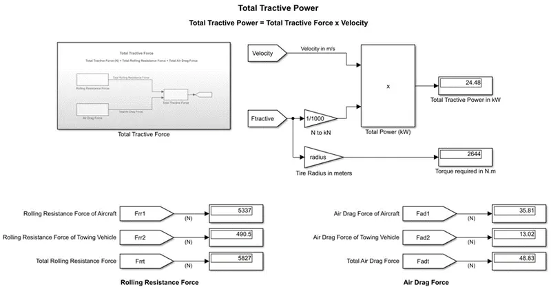
Subsystem : that is Rolling Resistance Force for Aircraft
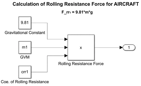
Subsystem for: Rolling Resistance Force for Towing Vehicle
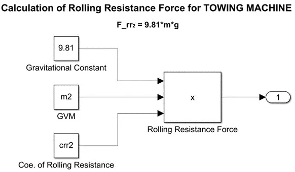
Subsystem for Total Rolling Resistance Force:
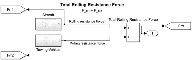
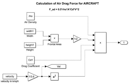
Subsystem for Air Drag Force for Aircraft
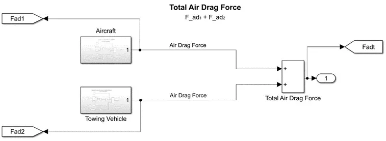
Subsystem for Total Air Drag Force :
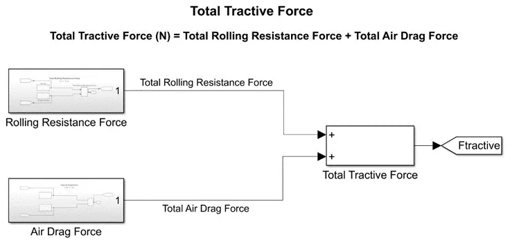
Subsystem for Total Tractive Force :
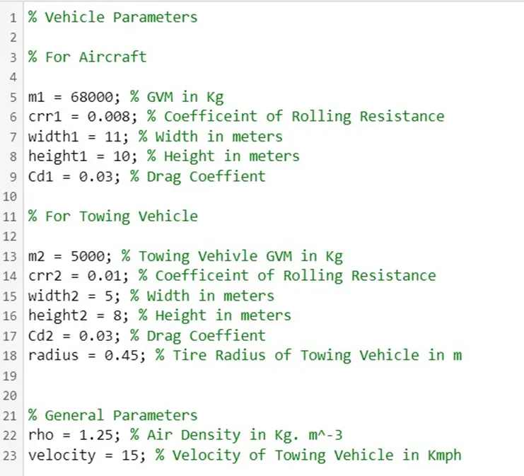
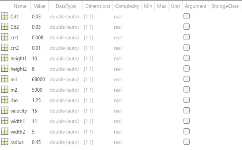
MATLAB code used in Model Explorer :
Model Explorer Window:
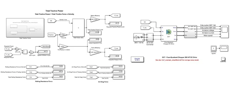
7. A)Design an electric powertrain with type of motor, its power rating, and energy requirement to fulfil aircraft towing application in Simulink. Estimate the duty cycle range to control the aircraft speed from zero to highest. Make all required assumptions. Prepare a table of assumed parameters. Draw a block diagram of powertrain. (Hint :DC7 Block)
B). Also, Design the parameters in excel sheet.
Since, we are continuing with the previous questions, lets consider the same parameters.
We calculated the required Force and Power as,
Force = 5876.2 N
Power = 24.48 kW
radius = 0.45 m
Considering motor efficiency as 95%, lets calculate the required output Power
Output Power of Motor = Calculated Power / efficiency
= 24.48/0.95
= 25.76 kW
For Required Torque calculation, consider a gear ratio of 0.5 and transmission efficiency to be 90%
Output Torque = (Traction Force * Radius of tire) / (Gear Ratio * efficiency)
= ( 5876.2 * 0.45 ) / ( 10 * 0.9 )
= 2644.29 / 9
= 293.81 Nm
Thus, Speed produced by motor, ω = Power/ Torque
= 25.76 kW / 293.81 Nm
= 87.67 rad/sec or 837 rpm
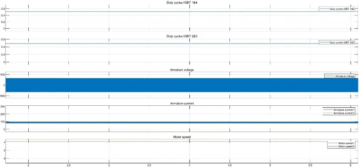
Here, we require a motor of minimum specification as,
Motor Power = 26kW or 35 hp
Motor Torque = 294 Nm
Motor Speed = 840 rpm
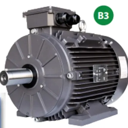
Thus, we can use a 3- phase Induction motor matching the above specifications as,
IE3 GR3-AL-63B3-2-B-D-35 model as the requirement.
The calculated parameters in excel sheet :
|
To calculate force & power required to push / pull an aircraft by a towing vehicle. |
||||
|
PARAMETER |
Aircraft |
Tow Vehicle |
||
|
Rolling Resistance Calculation |
68000.00 |
5000.00 |
||
|
Coefficient of Rolling Resistance |
0.008 |
0.01 |
||
|
Total Mass (Kg) |
68000.00 |
5000.00 |
||
|
Rolling Resistance Force (N) |
5336.64 |
490.50 |
||
|
Total Rolling Resistance Force (N) = Aircraft's Rolling Resistance Force + Tow vehicle's Rolling Resistance Force |
5827.14 |
|||
|
Air Drag Calculation |
|
|||
|
Air Density (Kg/m3) |
1.25 |
1.25 |
||
|
Width (m) |
11.00 |
5.00 |
||
|
Height (m) |
10.00 |
8.00 |
||
|
Drag Coefficient |
0.03 |
0.03 |
||
|
Speed (Kmph) |
15.00 |
15.00 |
||
|
Frontal Area (m2) |
110.00 |
40.00 |
||
|
Speed in m/s |
4.17 |
4.17 |
||
|
Air Drag Force (N) |
38.19 |
10.85 |
||
|
Total Air Drag Force (N) = Aircraft's Air Drag Force + Tow vehicle's Air Drag Force |
49.05 |
|||
|
Tractive Force exerted (N) = Air Drag Force + Rolling Resistance Force |
5374.83 |
501.35 |
||
|
Total Tractive Force exerted on Tow vehicle (N) = Total Air Drag Force + Total Rolling Resistance Force |
5876.19 |
|||
|
Total Power at given speed (kW) |
22.40 |
2.09 |
||
|
Total Power required for Push/Pull at given speed (kW) |
24.48 |
|||
|
radius of Tire (m) |
- |
0.45 |
||
|
Efficiency of Motor |
0.95 |
|||
|
Gear Ratio |
10.00 |
|||
|
Efficiency of Transmission |
0.90 |
|||
|
Required Output Power of Motor (kW) |
25.77 |
|||
|
Required Torque of Motor (N. m) |
293.81 |
|||
|
Speed developed by Motor (rpm) |
838.00 |
|||
Conclusions :
Part A:
1. The total weight of various types of aircrafts were searched and listed out
2. Difference between ground speed and air speed were discussed
3. Necessity to use aircraft engine power to move it on the ground at Airport were discussed
4. The way an aircraft is pushed to runway when its ready to take off is studied
5. Take off power, tyre design, rolling resistance, tyre pressure, brake forces when landing were studied in detail
Part B:
6. A. With necessary assumptions, the force and power required to push / pull an aircraft by a towing vehicle were calculated
B. The model for the calculated force and power using simulink was developed
7. A. An electric powertrain with type of motor, it’s power rating, and energy requirement to fulfill aircraft towing application in Simulink designed and estimation of the duty cycle with range to control the aircraft speed from zero to highest was calculated by making all required assumptions and a table of assumed parameters was prepared along with a block diagram of powertrain.
B. Also, the parameters formula sheet was calculated in excel sheet.
Links and References :
Gdrive Link:
https://drive.google.com/drive/folders/1k1LDBpflgcRVjVnLT8encLv3j49wYmKq
References :
- Mathworks documentation
- Wikipedia
- Google images