Week -2
AIM :
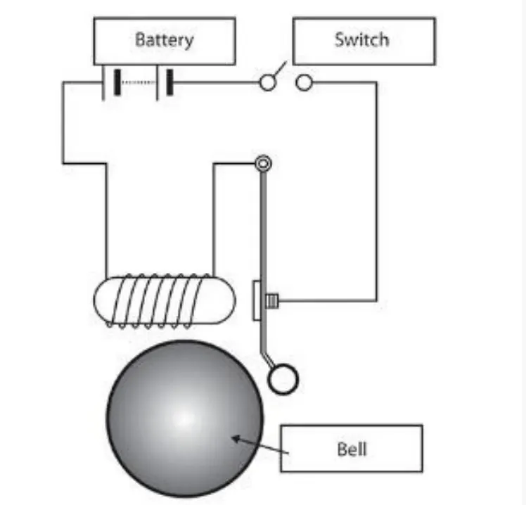
1) To make a simulink model of a Doorbell using the solenoid block :
2) To use a Thermistor to sense the temperature of a heater and turn ON or OFF the fan as per the below temperature conditions :
Temperature source: 20 °C from 0 to 10 seconds,
27 °C from 10 to 30 seconds, 23 °C from 30 to 50 seconds
Fan conditions: ON if the temperature above 25 °C, OFF otherwise
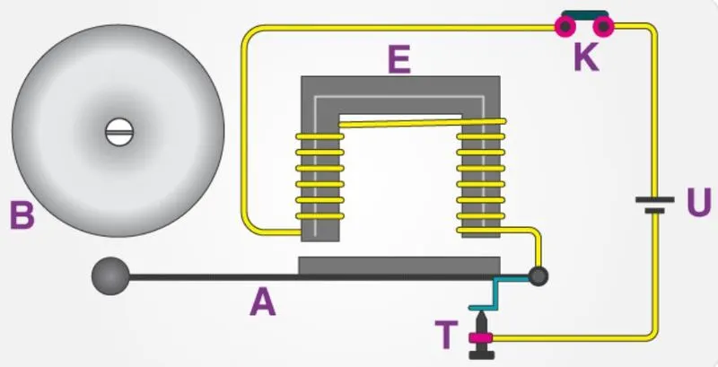
The solenoid is an electromagnet and on passing current through the conducting wires a magnetic field is generated around it and which attaracts magnetic materials
and when the switch of the bell is pressed the current passes through the circuit thereby exciting the electromagnet and
pulling the plunger towards the metal portion and this produces a ringing sound.
Now we try to make the simulink blocks for the same that is solenoid doorbell, and there is a need to understand the blocks used and the working mechanism and the blocks involved along with their characteristics and their role in doorbell simulation
Simulink Diagram :
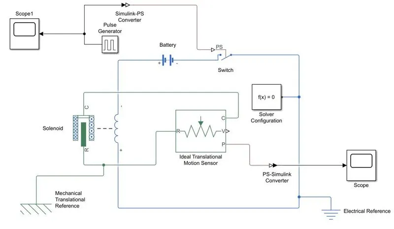
Simulink Diagram Explanation :
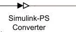
1.PS-simulink and simulink-ps converter :
These basically convert from physical system to simulink signals and vice versa
2. Scope:
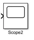
These blocks give the output in the form of x axis and y axis
3. Pulse Generator:
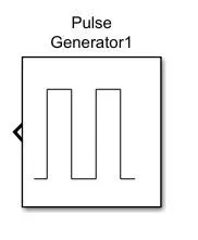
Pulse generator is an analog input that has amplitute and frequency with which input is transmitted
4. Electrical and mechanical references
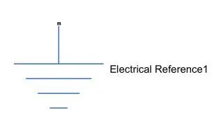
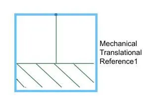
It is simply a reference block in which the system has a ground source as a base, or in other words it is used for grounding
5. Solenoid:
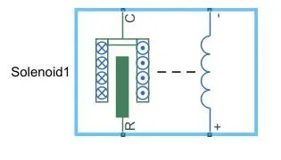
It is a electromagnetic device which is represented as below
6. Battery:
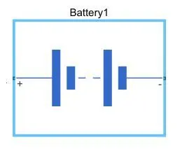
It is a device with positive and negative terminal for electric circuit for electric flow.
7. Switch:
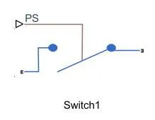
It is a device that completes the electric circuit for current flow. It can be controlled manually or automatically depending the type of the switch
8. Ideal translation motion sensor:
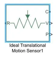
It is sensor that provides the provision or velocity input for the system to generate output
9. Solver configuration:
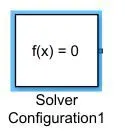
It is a type of lock that acts as a complete equation for where f(x)=0; where we find the value of x and generate the output which represents the block diagram as an equation.
Before the simulation we need to set up an input parameter. Here the pulse generator where the delay in seconds should be 2 seconds with the amplitute 1 and the pulse time should be 4 seconds to make the same with half and with 50% pulse width.
Pulse generator is given as the input with following parameters amplitude=1, period=2 seconds, pluse width (% of period) :50 , phase delay(in seconds): 2 seconds and the pulse type:(time based) and time(t): simulation time is used, here the condition is that the bell is engaged for 2 seconds and then it is released .
Same condition can also be implemented for 4 seconds, 6 seconds, and so on ....and with the pulse width as 50% of the time given such as 6 seconds or 4 seconds or that is 2 seconds and the phase delay is given as the 2 seconds so the simulation starts from the disengaged condition of the switch at starting.
The signal from the pulse generator is converted using a simulink to ps converter and it is given as the input to the switch, and a solenoid block is connected to a battery block.
The voltage of the battery connected was made same as that of the rated voltage in the solenoid, and the switch is being connected to the same circuit and the initial position was set to 5mm in translational motion sensor and both the electrical and mechanical references were connected to the circuit and the output of the ideal translational motiona sensor is converted using a PS-simulink converter and is connected to the scope block to get the output and the display results and a scope is also connected to the input block to completely see the behaviour of the input and the spring constants along with the damping parameters of solenoid block were altered to obtain the desired results on the output graph.
OUTPUT GRAPH EXPLANATION :
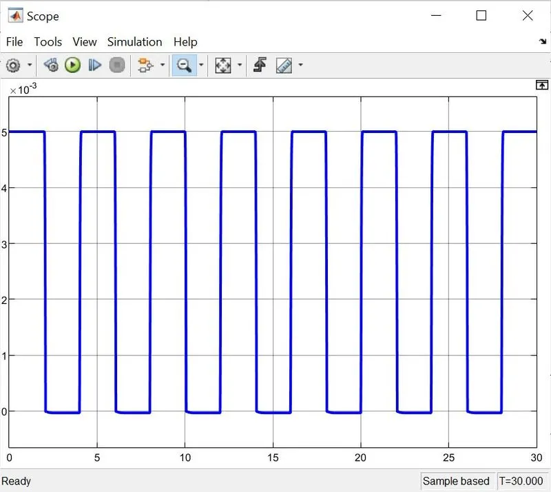
Thus, the simulation was run for 20 seconds and the results obtained were shown as above and it can be observed that at each 2 seconds of the interval the bell is ringing.
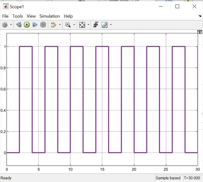
The pulse generator block is used and the pulse is such that every 2 second it is ON
The above image shows that the pulse pattern is given as the input and this cycle is for 30 seconds
as the circuit is to be closed for the only in the given interval of 2 seconds a switch block is used and the switch block has a threshold value of 0.8 and the pulse generator has the has the threshold value of 1 and the switch will only close when the value is more than 0.8 and this is connected to the solenoid block which contains the plunger arragement and initially when the plunger is away from C the value of X is 5mm and when the plunger is near C the value of X is 5mm and it can be seen that the output graph of plunger distance vs time and the position of the plunger is obtained by using the ideal translational motion sensor, and to avoid the spikes damping value needs to be given in the solenoid block as 6, to avoid the spikes in the output, in practical situation these spikes are caused due to electromagnetic interferences.
2.AIM : To use a thermistor to sense the temperature of a heater & turn on or turn off the fan as per below conditions
In this we are going to use the similar type of the procedure and simulate a thermistor and to sense the temperature of the heater
What is Thermistor ?
A Thermistor in other words is a thermal resistor which has an electrical resistance which varies with changes in temperature and all the resistors will have some resistances which will vary and fluctuate slightly with temperature and in short a thermistor is a device that is very sensitive to the temperature changes. Thermistor acts as a passive component in a circuit and thermistors very accurate and low cost or cheap and very robust way to measure the temperature and the main problem is that thermistors do not work very well in extremely hot and cold temperatures and they are the sensor of choice for many different applications and below are some temperature source and given conditions in our scenario :
20 °C from 0 to 10 seconds
27 °C from 10 to 30 seconds
23 °C from 30 to 50 seconds
Fan conditions: ON if the temperature above 25 °C, OFF otherwise
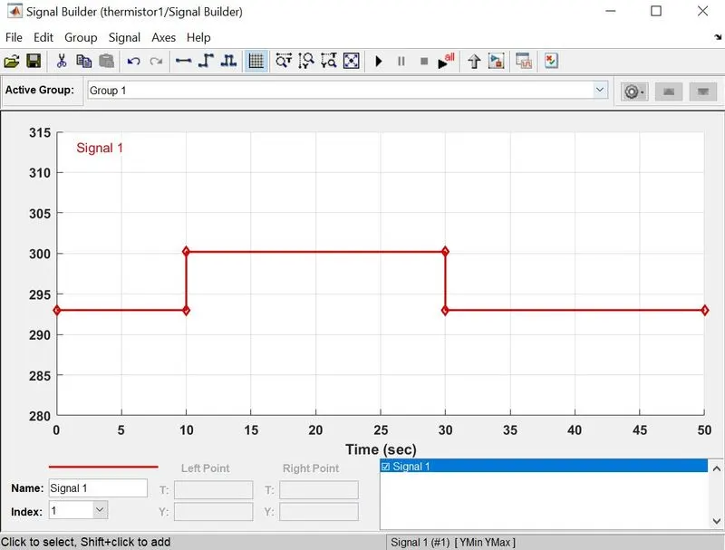
The input signal corresponding to the above parameters is given using a signal buider block,
and the signal builder block can be set according to the need of the specifications,
for example:
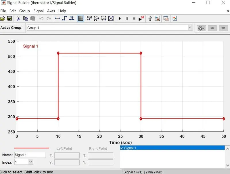
and in our case it is :
20 °C from 0 to 10 seconds
27 °C from 10 to 30 seconds
23 °C from 30 to 50 seconds
Fan conditions: ON if the temperature above 25 °C, OFF otherwise
which is represented as below :
The overall simulink diagram can be displayed as follows :
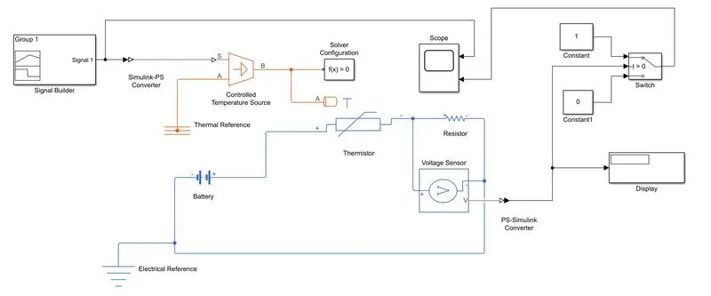
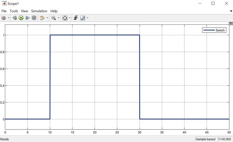
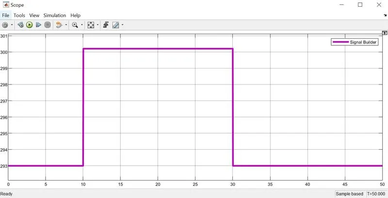
The above requirements are such that the fan should be ON when the temperature is sensed greater than 25 degree celsius and to fulfil this objective you can see these in the signal builder blocks where the input is inserted with these signals and at the different temperatures the voltage sinal is passed to the switch and the switch configuration is in such a way that it is open when the voltage across the voltmeter is approx less than 0.2333 v that is in our case the value is taken as 0.1099933 for the threshold value to match and tempetrature less than 25 degree celsuis and after running for 50 secs we need to provide the display as an input to the switch for the ON and OFF conditions
Conclusions :
1. Thus , the simulation was successfully executed for solenoid doorbell and a thermistor to sense the temperature of a heater & turn on or turn off the fan siumulated in matlab and simulink environment for temperature source: 20 °C from 0 to 10 seconds, 27 °C from 10 to 30 seconds, 23 °C from 30 to 50 seconds with fan conditions: ON if the temperature above 25 °C, OFF otherwise
2. Similar type of the system can be studied or modeled based on the given conditions
3. It gives more knowledge about ON and OFF conditions at different time specified.
Click the below G-drive link to explore files:
https://drive.google.com/drive/folders/1mFx0UtBRnEyArw3gq9i37tsj-GlCBk6I