Week - 4
AIM :
1. To implement control logic of a “washing machine” using Stateflow as per given sequence:
- If the power supply is available, the system gets activated
- If the Water supply is not available, stop the process & indicate through LED
- Soaking time should be 200s followed by Washing time of 100s.
- Then rinsing happens for next 20s & dryer runs for 50s
After all the processes have completed turn on the finished LED
2. To make a Simulink chart for the “Gear shift” logic as per below conditions:
Speed Range(kmph) Gear
0 to 15 1
16 to 25 2
26 to 40 3
41 to 60 4
Above 61 5
To Give speed input while the simulation is running & display the gear number.
1. To implement control logic of a “washing machine” using Stateflow as per given sequence:
- If the power supply is available, the system gets activated
- If the Water supply is not available, stop the process & indicate through LED
- Soaking time should be 200s followed by Washing time of 100s.
- Then rinsing happens for next 20s & dryer runs for 50s
After all the processes have completed turn on the finished LED
AIM :
To implement a control logic of the washing machine using stateflow
Some of the steps involved in washing machine are soaring washing rinsing and drying
1. Soaking
2. Washing
3. Rinsing
4. Drying
Conditions:
If the power is on the system should be activated
The process should actually take place when the water is available or else stop the process with indicating LED
Soaking time is 200 seconds
Washing time is 100 seconds
Rinsing time is 100 seconds
Drying time is 50 seconds
And After finishing all the processes Finish LED should glow as RED
Washing Machine with its Components And Functions :
An Inner Drum :
This is the chamber in which the dirty clothes are put. On noticing properly, one may see many holes in this, and these holes are made so that the water can enter the drum and the cleaning process also takes place here.
Paddles :
paddles are the ridges present on the drum’s edges and help move the clothes while it is present inside the drum.
The Outer Drum :
This is the drum inside which the inner drum is present. This is the water-tight area of the machine that prevents the leakage of water from the machine.
Agitator :
This is not a default part of the washing machine. Agitators are present only in the premium models and help turn around the machine’s clothes and make cleaning more effective.
Thermostat And Heating Element :
This part of the machine checks the water temperature and heats it according to the need.
Pump :
It helps remove the water from the drum after the cleaning process is over.
Pipes And Valves :
These elements are often overlooked but are the machine’s most fundamental elements. These pipes and valves help maintain the to and fro movement of the water from the drum, allowing the washing to occur.
Washing Machine Working Principle :
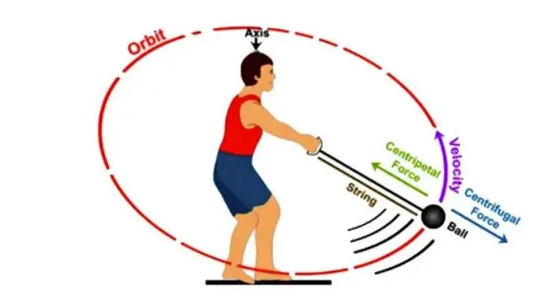
Detailed Explanation About Washing Machine :
The main principles behind the working of a washing machine are the centrifugal and centripetal forces and when the centrifugation actually help to quicken the process of sedimentation of the different density particles to clean the laundry in the washing machine.
The washing machine operates in two primary cycles. These are the wash cycle and the rinse cycle.The wash cycle involves the principle of centrifugal force. This force’s direction is from inside to outside, which makes sure that every part of the cloth is rinsed adequately in the soap water mixed in the machine.The rinse cycle involves the principle of centripetal force. This force acts from outside to inside and creates a vacuum-like space in the middle of the washing machine.
These two cycles work one after another several time, and as a result, the entire cleaning process occurs.
Step by step mechanism of the working of washing machine
Firstly before the washing machine starts to operate, you need to get it ready for the washing. Getting the machine ready includes filling the washing machine with water held in the outer drum and stopping the water from leaking while operating. Then you put the clothes inside the inner drum.
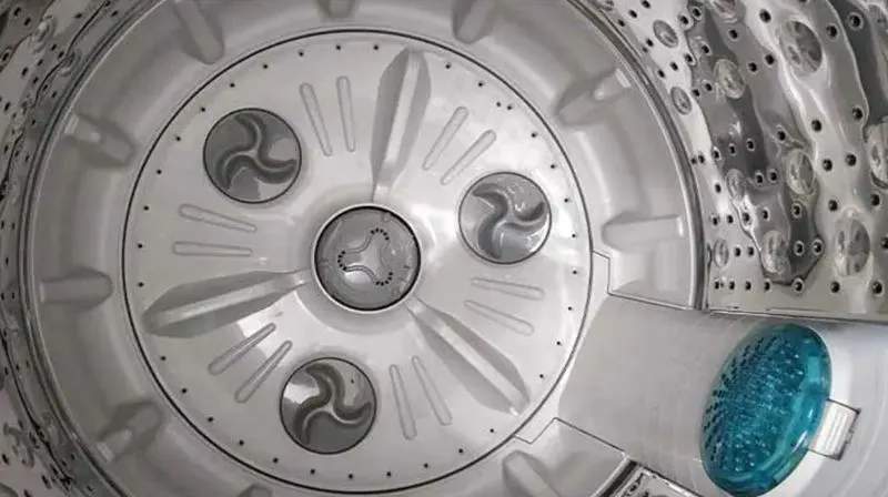
The inner drum is the drum on which the different forces will give you a cleaner version of your clothes. Then you put the detergent into the machine, and after plugging in the device, we are ready to go.There is a thermostat present inside the washing machine.
After you turn on the device, the thermostat measures the temperature and increases the heat according to its need. When the water is hot enough for operation, the inner drum rotates back and forth on time, mixing the cloth properly with the soap water. Now the work of the detergent begins. We have all studied how soaps and detergents work, and due to the motion of the particles, detergents can do their job correctly and scrub off all the dirt molecules from the clothes.
And in the next step if one is using a fully automatic washing m/c then the machine itself opens the valves and lets the dirty water flow away. Then, the programmer opens the valves again to allow clean water to come into the drum.
After the clean water comes in, the inner drum again starts to rotate to rinse the clothes properly. This rinsing process, removing the dirty water, taking new water, and rinsing again is repeated several times to improve efficiency.
After the clothes’ proper rinsing, the machine starts to rotate the inner drum vigorously at a high speed of around 130 km/h. these force is from the inside to outside and flung apart the clothes from the inner edge to the drum’s outer edge.
This final churning allows the proper cleaning of clothes, and after this step, the remaining water is let out from the valve, and you get your set of clean clothes.
Now let us understand the same using Simulink logic as follows:
Overall Model :
The overall simulink model diagram can be represented as follows:
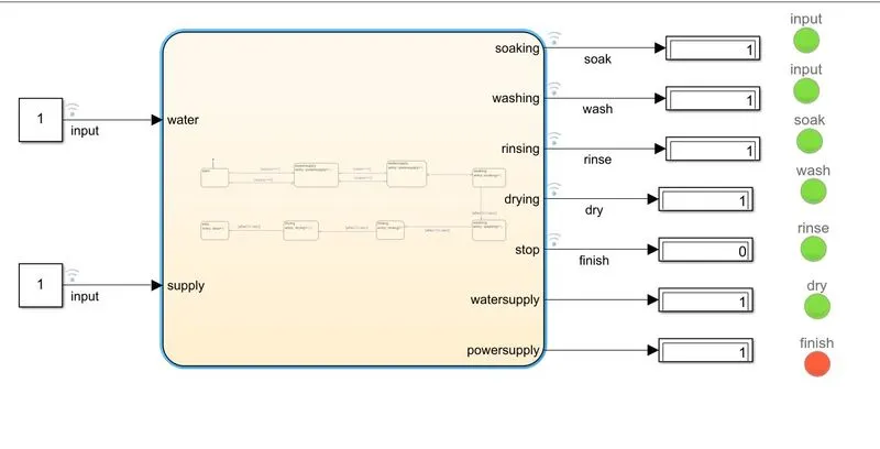
Steps involved in Simulink model using MATLAB :
1. Open the New Simulini in MATLAB for creating a new file
2. Now by adding constant blocks which can be tje two inputs that is , power supply and water supply
3. Add chart block for the logic that need to be applied for washing machine and chart block is a state flow logic used in the model After adding the chart block it appears link rose in color and the entire screen color will change .
4. Now inside the chart block some logics need to be implemented using the states and connection and which can be done by adding states for every step when the power supply is in ON and in OFF conditions and if the power is in ON condition the process will continue for the next step and so on .
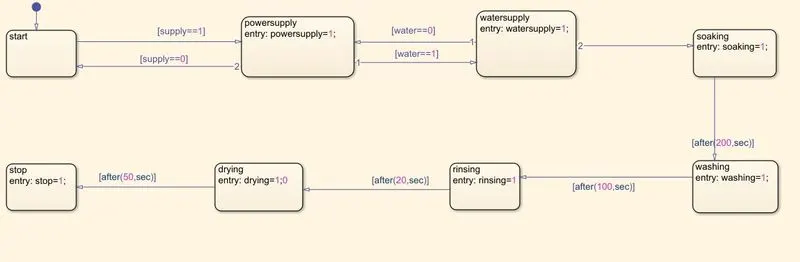
5. First is start block where power supply and the water supply are the two inputs given and the condition is set as [ supply==1 ] , and [supply==0], entry: power supply=1; and the second condition after this is Water supply .
6. Now the water supply state logic block is given with [water==0] and [water==1], condition and entry: water supply=1;
7. Now the Soaking state logic block is given with the condition entry: soaking=1; and after the 200 seconds the washing state occurs
8. Now the Washing state logic block is given with the condition of after (T=200 seconds) entry: washing=1; and the rinsing cycle should be given with the time of after (T=100 seconds)
9. Now the Rinsing state logic block is given with the condition entry:rinsing=1; and followed by this the drying block is implemented
10. Now the drying state logic block is given with the condition entry: drying=1,0 and after 1 minute of time rougly 60 seconds the drying process stops and the end process or the finish state or stop state occurs and in our state it is given as after (T=50 seconds) entry: stop=1;
11. stop or finsh or end process
12. Now the input data are given using the parameters table for the chart with specific values, for example for ON and OFF conditions as 1 and 0
13. Now each and every block came be displayed along with the names provided with the Lamps and assigning the values as, for Red equal to OFF and 0 and for green indication which is as 1 .
14 . The below show simulink model using MATLAB is run for T= 400 seconds and then the output values are captured as shown below:
Overall Chart representation with State flow logic diagram :
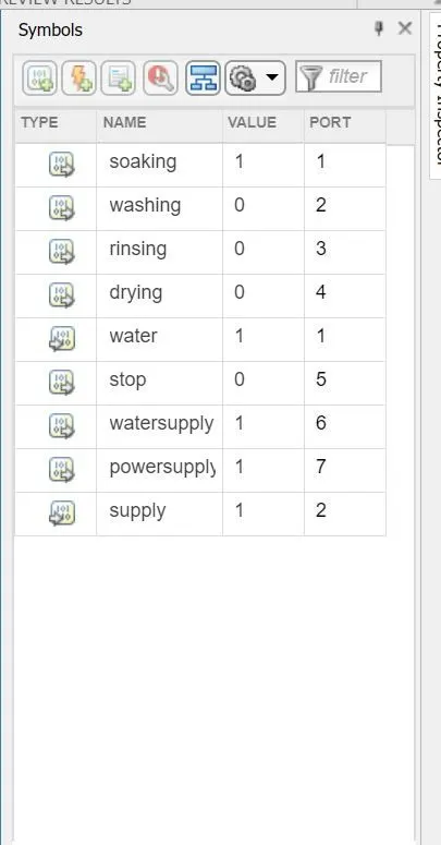
Parameters in chart :
Runtime and Conditions:
At starting state the model is created for without Power supply and the water supply
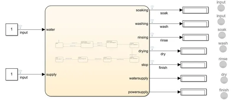
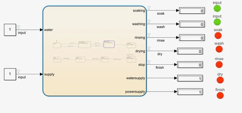
Now the Simulink Model which is created is compiled or run by giving the two inputs input 1 and input2 as Power supply and the water supply and at the initial state the two Green LED glows, here the value of LED is given with Green equal to 1 and Value ON and RED equal to 0 and OFF condition
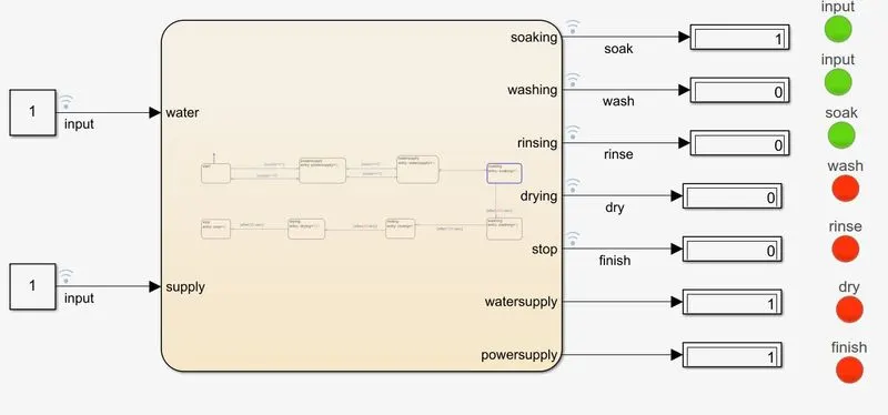
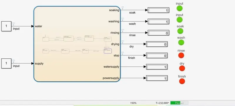
In our case whichever process is presently going on or whichever proces is ON that particular LED glows indicating that the process is
running and now in the below diagram the soaking state is indicated and the capture was made during the transition from 0 to 1 and after soaking the washing process takes place
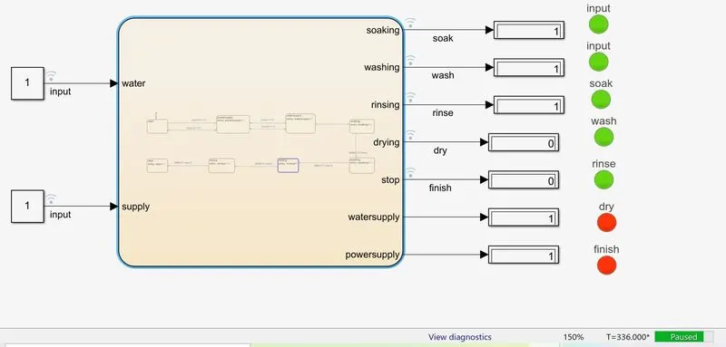
after soaking the washing process takes place after 200 seconds and followed by that is the rinsing process after the duration of 20 to 30 seconds
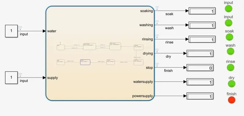
The step after this the drying or drying state process takes place that is after 1 minute but in our case roughly it is taken as 50 seconds
After completion of all the processes or the steps all the LED would glow to Green indicating that the entire wash cycle is finished and
the Red LED would glow to indicate the End process or the finish or the Stop State.
Now the conclusions can be discussed as below
Conclusions :
Thus, the state flow logic for the washing machine is created with Simulink using MATLAB and
the similar kind of approach can also be implemented for the Traffic light control and the start and stop logic using ON and OFF conditions state logic.
AIM:
2. To make a simulink chart for "Gear shift" logic under certain conditions.
Speed Range(kmph) Gear
0 to 15 1
16 to 25 2
26 to 40 3
41 to 60 4
Above 61 5
Giving the speed input while the simulation is running & display the gear number.
About Gear Mechanism in Brief:
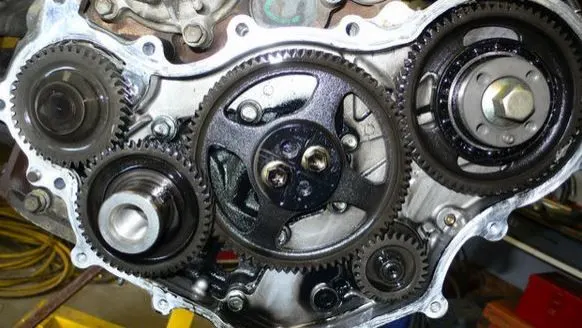
A gear is also called a cogwheel and is a type of simple machine that is used to manipulate the magnitude or direction of a force. Gears are used in combination and are linked together by their teeth and referred to as cogs - in order to form a "gear train".
These gear trains are useful for transferring energy from one part of a system to another. Systems that utilize gears and gear trains include bicycles, cars, electric screwdrivers, and many other common machines
Below Diagram shows the animation of a gear pair and it can be seen that the smaller gear is spinning faster in order to keep up with the larger number of teeth on the bigger gear

Now, each and every situation during the runtime or compilation time of simulink can be discussed as follows:
GEAR 1: From Gear 1 to Gear 2 speed range is considered as [s>15] and in reverse as [s<15]
when the value of speed is changed between 0 to 15 the dsiplay shows as 1
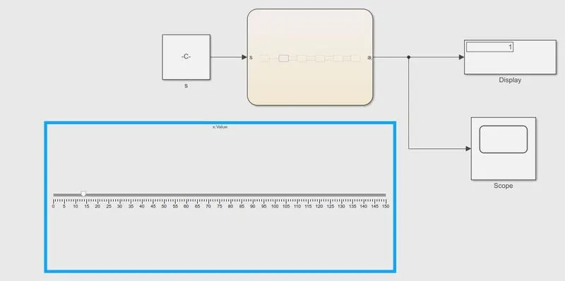
GEAR 2: From Gear 2 to Gear 3 speed range is considered as [s>25] and in reverse as [s<25]
When the value of speed is changed between 16 to 25 the dsiplay shows as 2
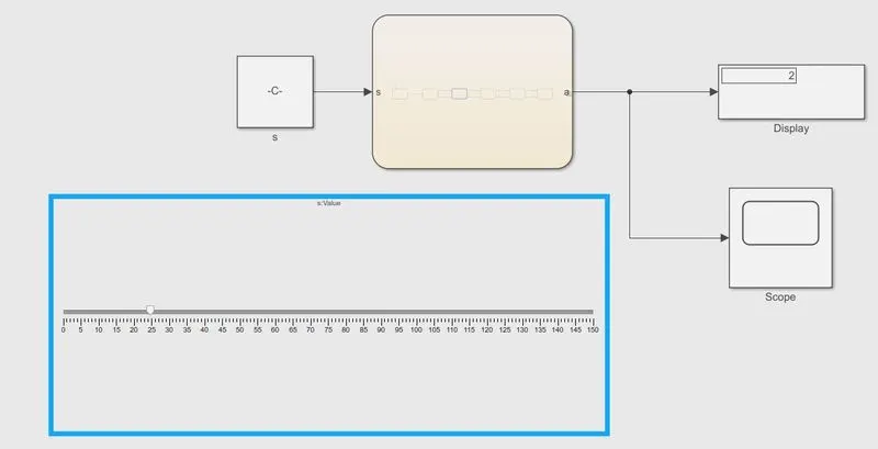
GEAR 3: From Gear 3 to Gear 4 speed range is considered as [s>40] and in reverse as [s<40]
When the value of speed is changed between 26 to 40 the dsiplay shows as 3
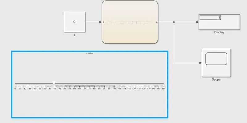
GEAR 4: From Gear 3 to Gear 4 speed range is considered as [s>60] and in reverse as [s<60]
when the value of speed is changed between 41 to 60 the dsiplay shows as 4
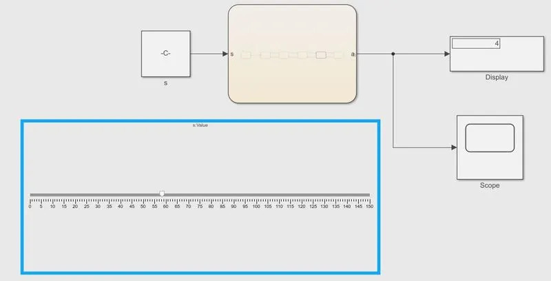
GEAR 5: After Gear 5 and above speed range is considered as [s>60] that is Above 61, as per the given conditions as stated above.
when the value of speed is changed in above 60 range the dsiplay shows as 5
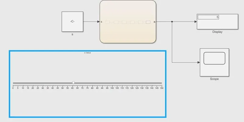
Overall state diagram for different speed ranges and their suitable speed for particular gear, and the detailed simulink diagram is below this as the chart made as the sub-system:
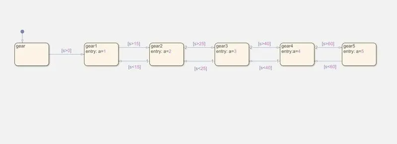
Simulink diagram having the chart embeded as sub-system inside the chart as shown from the above diagram
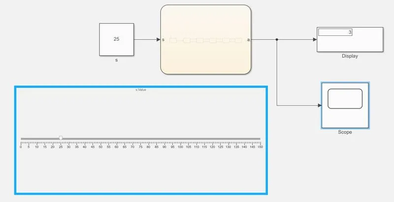
Steps in creating simulink model :
1. Open the simulink in MATLAB and create
2. Add a constant block and open the chart by double clicking on the same.
3. Create states for each and every gear that needs to be changed and create state block for input and output values and name the same as gear.
4. Create a new state for second gear by naming the same as gear 2 and as there are range of gears in both the direction there are some speed ranges for each gear
5. The Speed range from Gear 1 to Gear 2 is considered as [s>15] and in reverse as [s<15]
6. Now create the 3rd state can be created for the Gear 3 and the speed range from Gear 2 to Gear 3 is considered as [s>25] and in reverse as [s<25] which is assigned in the block
7. Now create the 4th state can be created for the Gear 4 and the speed range from Gear 3 to Gear 4 is considered as [s>40] and in reverse as [s<40] which is assigned in the block
8. Now create the 5th state can be created for the Gear 5 and the speed range from Gear 4 to Gear 5 is considered as [s>60] and in reverse as [s<60] which is assigned in the state block
9. Assign the parameters value for 's' and 'a' and given the slider range as 100 or 150 and according the simulation run time T=100 or T=150 seconds can be set to define the upper limit run value which is assigned as the runtime and can be varied also
10. On making changes in the slider block while the simulation is running or compiling the output can values for certain conditions given below are clearly observed as shown below:
Speed Range(kmph) Gear
0 to 15 1
16 to 25 2
26 to 40 3
41 to 60 4
Above 61 5
The same speed variations are obtained in the scope as below along with the gear 1 to gear 5 as show below
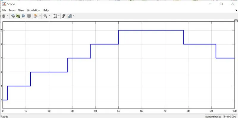
Conclusions :
1. Thus, the state flow logic for the washing machine is created with Simulink using MATLAB.
2. Thus, the state flow logic is created for the gear shift in Simulink using MATLAB for different speed values and the suitable gear ranges.
Alternatively G-drive link below can be clicked to view the captures and the entire work and simulink models :
https://drive.google.com/drive/folders/1Mw7ra902qNDQ_LY-7cUVQmdhYVcRmPuk