Project-1: Powertrain for aircraft in runways
1. Search and list out the total weight of various types of aircraft.
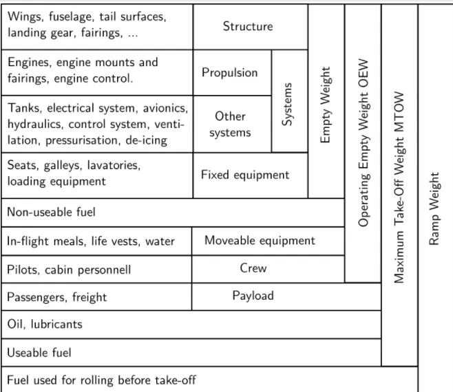
Brief explanation:
- Manufacturer's empty weight - they are the weights of an integral part of an aircraft that includes structure (wings, tails, landing gears), propulsion(engine, mounts, and engine control), and other systems (electrical, hydraulics, and control) and fixed types of equipment(seats, lavatories).
- Zero fuel weight - they are the total weight of aircraft excluding the useable fuel on board.
- Operational empty weight - they include manufacturer's empty weights, movable equipment(water), crew, and, non-useable fuel weights (fuel which results in providing an engine with a constant fuel supply despite changes in aircraft pitch, roll, and raw, turbulence, and varying gravitational forces.)
- Maximum take-off weight- they are the total weight of aircraft including payload, operational empty weight, and useable fuel. it is the maximum weight that is permitted before the take-off.
- Regulated take-off weight - the weight values are regulated according to various factors like altitude, air temperature, runway length and cannot be higher than maximum take-off weight. it varies for every take-off.
- Ramp weight - they are the addition of maximum take-off weights and fuel weights which are used for rolling or towing aircraft to the runways or gate and for running up of the engine.
- Maximum landing weight - they are the maximum gross weight that is designed or specified for ensuing safe landings. they are less than the maximum take-off weight since aircraft while landing will be lighter than the take-offs because of the burned fuels.
all these weights are considered in calculating the total weight of the aircraft.
the total weights of some types of aircraft
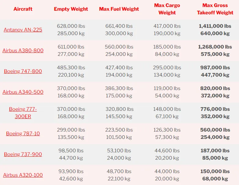 source: pilot teacher
2. Is there any difference between ground speed and airspeed?
Ground speed
- It is the speed of aircraft relative to the ground
- for understanding, consider the aircraft shadow moving across the ground.
Airspeed
- It is the actual speed of aircraft flying in the air through the engine power.
If there is no wind,
Ground speed = Airspeed
If there is wind flowing in the direction of the aircraft,
Ground speed - wind speed = Airspeed
If there is wind against the aircraft,
Ground speed + wind speed = Airspeed
3. Why is it not recommended to use aircraft engine power to move it on the ground at the Airport?
An aircraft engine is a more powerful engine and the power created from its propulsion system is very high. and the reasons why it is not recommended to use engine power to move it on the ground at the airport,
- Fuel consumption will be high which leads to high fuel costs.
- they will generate very high noise leads to noise pollution
- due to high engine thrust, objects or personnel may pull inside leading to fatal accidents and may affect the airplane structure and controls.
4. How an aircraft is pushed to the runway when it is ready to take off?
Planes move by pulling or pushing themselves through the air rather than applying engine power to move the wheels like ground vehicles. they have no forward or reverse gears and the engine does not run backward. and hence they are usually pushed back by the pushback tractors or tugs away from the terminal buildings or parking position to the runways. Although many aircraft are capable of moving themselves reverse on the ground using powerback procedure, where aircraft move backward on the ground using the engine power along with the reverse thurst they are often prohibited by the manufacturer.
Pushback:
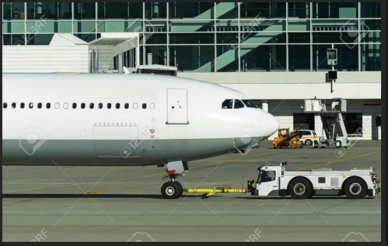 source: google
Only the reverse action is down by the pushback tractors, where if the aircraft is away from the parking position and now wants to move forward is done by taxiing. taxiing is the movement of aircraft on the ground using its own engine power.
Taxiing:
 source: alamy
5. Learn about take-off power, tire design, rolling resistance, tire pressure, brake forces when landing.
Take-off power
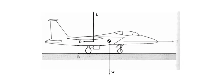
For the aircraft to take off from the ground and become airborne we have to consider various terms and specifications. they include various velocity and control points, total take-off distance, thurst, drag, lift, weight, and rolling resistance. the amount of power that an engine is allowed to produce for a limited period of time for take-off is called take-off power.
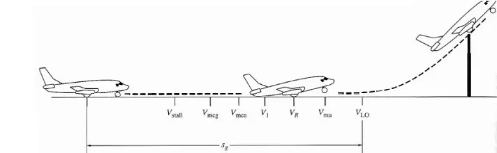
 source:google
with the take-off performance calculation, we can able to calculate the take-off power
M * dv /dt = T - D - R
where M = mass, dv/dt = acceleration, T= thrust, D = Drag, R = rolling resistance
M * dv/dt = T - D - C_rr (W - L)
where C_rr = coefficient of rolling resistance, W = weight, L = lift.
power can be calculated with the force and velocity.
Tire design
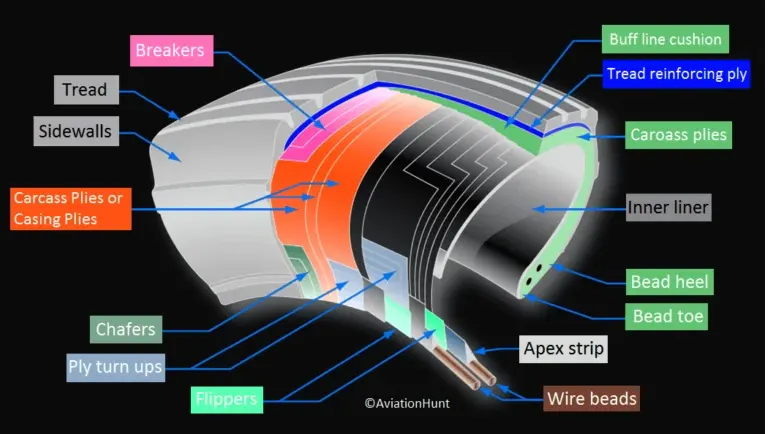
- tires are made up of carcass piles
- they support the weight of aircraft while it is on the ground
- they provide necessary traction for braking and stopping of aircraft
- they absorb the shock and vibrations when landing
- they provide cushioning to overcome roughness when take-off, taxiing, and pushback operations
Retreading - it is a method of restoring a worn tire by renewing the tread area
Load rating - maximum load at a specified inflation pressure
Ply rating - it is the index of tire strength and used to find the maximum load rating and inflation pressure
Speed rating - maximum take-off speed to which the tire has been tested
Skid depth - the distance between tread surface and deepest groove as measured in the mould.
Nowadays all tires are tubeless and radial in design. they are also made up of conductive materials for earthing of static charges.
Tire pressure
Generally, aircraft tires operate at high pressures, up to 200psi for airliners and even higher for business jets. with the test results, these tires are able to sustain pressures of a maximum of 800 psi before bursting. they are tested for extreme conditions like emergency landing or braking or rejected take-off. without proper pressure, the tires may result in under-inflation leading to tread wear, less traction, components getting separated inside the tires, and accidents.
Rolling resistance
The rolling resistance is the force per unit vehicle weight required to move the vehicle on the ground. the rolling resistance coefficient is defined by the following equations,
F = C_rr * N || F = C_rr * Mass * gravity
where, F = rolling resistance force
C_rr = rolling resistance coefficient
N = normal force, the force perpendicular to the surface on which the wheel is rolling.
Brake force when landing
when the pilot presses the brake pedal, an electrical signal is sent to the hydraulic system of the aircraft. the main landing gear will have hydraulic actuators and here, hydraulic fluid at 3,000 pounds per square inch is used to force the brake unit against the wheel. the additional systems which help in slowing down the aircraft on landing are the spoilers and the reverse thrust.
6. A. With the necessary assumption, calculate the force and power required to push/pull an aircraft by a towing vehicle.
Formula used:
(here we are considering rolling resistance force and aerodynamic force)
1. rolling resistance force = coefficient of rolling resistance * m *g 1N = kgm/s^2
2. aerodynamic force = 0.5 * air density * area * drag coefficient * velocity^2
3. Power = force * velocity kw
Inputs
Mass of aircraft = 260000 kg
Mass of towing vehicle = 30000 kg
C_rr of aircraft = 0.005
C_rr of towing vehicle = 0.003
g = 9.81
air density = 1.25 kg/m^3
frontal area = 20 m^2
C_drag = 0.04
velocity = 25 km/h = 25/3.6 = 6.94 m/s
CALCULATION
for towing vehicle,
rolling resistance force = 0.003 * 30000 * 9.81
= 882.9 N
for aircraft,
rolling resistance force = 0.005 * 260000 * 9.81
= 12753 N
total rolling resistance force = 882.9 + 127530
= 13635.9 N
aerodynamic force = 0.5 * 20 * 1.25 * 0.04 * (6.94)^2
= 24.08 N
force = rolling resistance force + aerodynamic force
= 13635.9 + 24.08
= 13659.98
power = force * velocity
= 13659.98 * 6.94
= 94.8 Kw
B. Develop the model for the calculated force and power using Simulink.
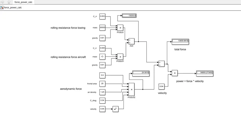
The above inputs and formula are used for creating this model
Simulink model
EXPLANATION
- constant, add, product, and display block are used
- all inputs are given using constant blocks
- respective forces are calculated using formulas using product blocks
- both the rolling resistance force and aerodynamic forces are added using add block
- display blocks are used to view the results
- here we can see the final result power = force * velocity = 94.8 kW.
https://drive.google.com/file/d/1VwuvRxRmt2FvSBkkMGm3lwDtOlKqjAAR/view?usp=sharing
7. A. Design an electric powertrain with the type of motor, its power rating, and energy requirement to fulfill aircraft towing application in Simulink. Estimate the duty cycle range to control the aircraft speed from zero to highest. Make all required assumptions. Prepare a table of assumed parameters. Draw a block diagram of the powertrain.
The inputs and results from 6. A is considered. so,
total traction force = 13.659 kN
power = 94.8 kW
Additional inputs
radius of wheel = 0.508 m
gear ratio = 10
efficiency_t = 85%
efficiency_m = 90 %
to find motor torque,
motor torque = F * r / G * efficiency_t
= 13.659 * 0.508 / 10 * 0.85
= 0.816 kNm
after considering the efficiencies,
torque required = 0.816 / 0.9 = 0.907 kNm
power required = 94.8 / (0.85*0.9) = 123.92 kW
to find the energy requirement
consider we are using the towing vehicle for 20 minutes,
t = 20 min = 0.333 hours
Energy = power* t
= 123.92 * 0.333
= 41.26 kWh
for the towing application, let us consider
battery voltage = 550V 300 A, rated power = 165kw
and with the required power 123.92 kw,
dutycycle = 123.92/165
= 0.75 = 75%
so the estimated dutycycle range will be from 0 - 75 %.
SIMULINK MODEL
EXPLANATION
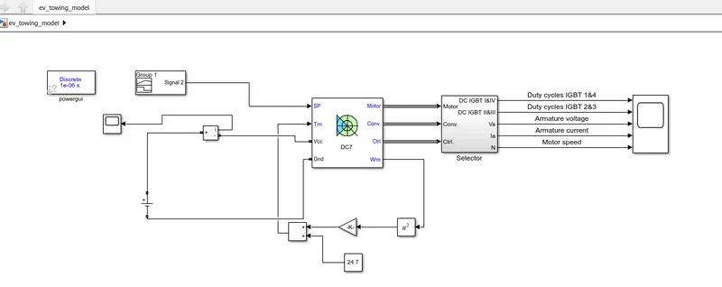
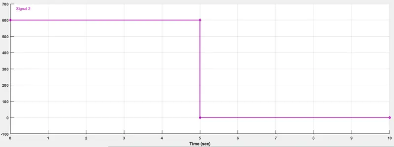
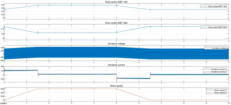
DC voltage of 550 V is used. speed reference is given using a signal builder and speed-torque characteristics T=24.7+0.005*speed^2 is given.DC7 block is used and scopes are used for results.
OUTPUT
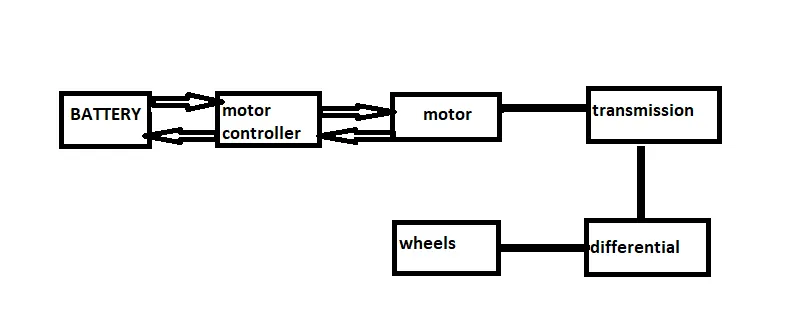
block diagram of a powertrain
https://drive.google.com/file/d/1I1W7q2y0canNTEq0Dtl-qlHOW38P-biB/view?usp=sharing
B. Also, Design the parameters in an excel sheet.
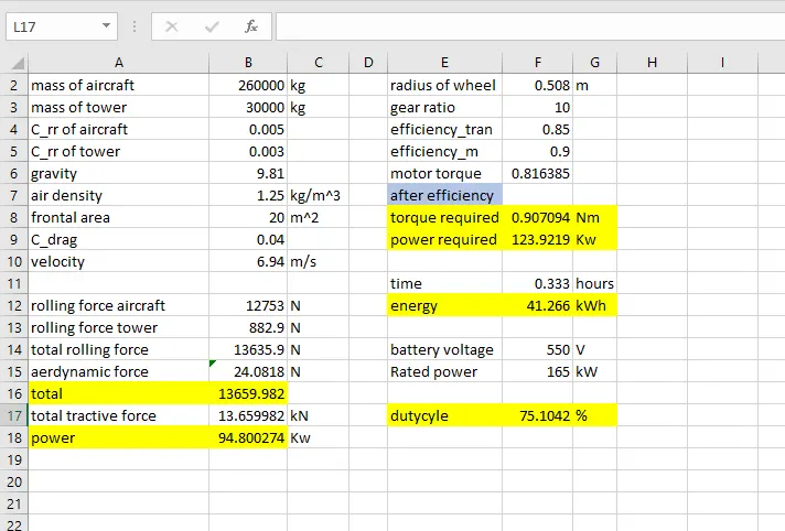
https://docs.google.com/spreadsheets/d/1lsC3_BwgsvDYrQRO6GotJaaV_BI4CCvx/edit?usp=sharing&ouid=115981456646120318324&rtpof=true&sd=true
.