Project-1: Powertrain for aircraft in runways
PART-A:
1. Search and list out the total weight of various types of aircrafts ?
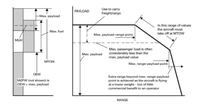
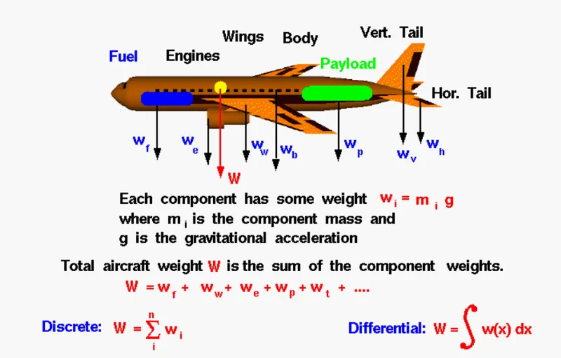
The aircraft gross weight (also known as the all-up weight and abbreviated AUW) is the total aircraft weight at any moment during its flight or during ground operation.
An aircraft's gross weight will decrease during a flight due to fuel and oil consumption. An aircraft's gross weight may also vary during a flight due to dropping of payload or due to refuelling operations.
At the moment of releasing its brakes, the gross weight of an aircraft is equal to its takeoff weight. During flight, an aircraft's gross weight is referred to as the en-route weight or in-flight weight.
Other weights related to aircrafts:
An aircraft's gross weight is limited by several weight restrictions in order to avoid overloading its structure or to avoid unacceptable performance or handling qualities during its operation.
Aircraft gross weight limits are established during an aircraft's design and certification period and are laid down in the aircraft's type certificate and manufacturer specification documents.
The absolute maximum weight capabilities of a given aircraft are referred to as the structural weight limits. The structural weight limits are based on aircraft maximum structural capability and define the envelope for the CG charts (both maximum weight and CG limits).
An aircraft's structural weight capability is typically a function of when the aircraft was manufactured, and in some cases, old aircraft can have their structural weight capability increased by structural modifications.
Maximum design taxi weight (MDTW)
The maximum design taxi weight (also known as the maximum design ramp weight (MDRW)) is the maximum weight certificated for aircraft manoeuvring on the ground (taxiing or towing) as limited by aircraft strength and airworthiness requirements.
Maximum design takeoff weight (MDTOW)
Is the maximum certificated design weight when the brakes are released for takeoff and is the greatest weight for which compliance with the relevant structural and engineering requirements has been demonstrated by the manufacturer.
Maximum design landing weight (MDLW)
The maximum certificated design weight at which the aircraft meets the appropriate landing certification requirements. It generally depends on the landing gear strength or the landing impact loads on certain parts of the wing structure.
The MDLW must not exceed the MDTOW.
The maximum landing weight is typically designed for 10 feet per second (600 feet per minute) sink rate at touch down with no structural damage.
Maximum design zero-fuel weight (MDZFW)
The maximum certificated design weight of the aircraft without any fuel loaded and other specified usable agents (engine injection fluid, and other consumable propulsion agents). It is the maximum weight permitted before usable fuel and other specified usable fluids are loaded in specified sections of the airplane. The MDZFW is limited by strength and airworthiness requirements. At this weight, the subsequent addition of fuel will not result in the aircraft design strength being exceeded. The weight difference between the MDTOW and the MDZFW may be utilised only for the addition of fuel.
Minimum flight weight (MFW)
Minimum certificated weight for flight as limited by aircraft strength and airworthiness requirements.
Below are the total weights of few aircrafts used around the globe:
| Type | MTOW [kg] | MLW [tonnes] | TOR [m] | LR [m] | ICAO category | FAA category |
| Antonov An-225 | 6,40,000 | 591.7 | 3500 | Heavy | Super | |
| Scaled Composites Model 351 Stratolaunch | 5,89,670 | 3660 | Heavy | Super | ||
| Airbus A380-800[1][2][3] | 5,75,000 | 394 | 3100 | 1930 | Super | Super |
| Boeing 747-8F | 4,47,700 | 346.091 | 3100 | 1800 | Heavy | Heavy |
| Boeing 747-8 | 4,43,613 | 306.175 | 3100 | Heavy | Heavy | |
| Boeing 747-400ER | 4,12,770 | 295.742 | 3090 | Heavy | Heavy | |
| Antonov An-124-100M | 4,05,060 | 330 | 2520 | 900 | Heavy | Heavy |
| Boeing 747-400 | 3,96,900 | 295.742 | 3018 | 2179 | Heavy | Heavy |
| Lockheed C-5 Galaxy[4][5][6] | 3,81,000 | 288.417 | 2530 | 1494 | Heavy | Heavy |
| Boeing 747-200[7] | 3,77,840 | 285.7 | 3338 | 2109 | Heavy | Heavy |
| Boeing 747-300[7] | 3,77,840 | 260.32 | 3222 | 1905 | Heavy | Heavy |
| Airbus A340-500[8] | 3,71,950 | 240 | 3050 | 2010 | Heavy | Heavy |
| Airbus A340-600[8] | 3,67,400 | 256 | 3100 | 2100 | Heavy | Heavy |
| Boeing 777F | 3,47,800 | 260.816 | 2830 | Heavy | Heavy |
2. What is the difference between ground speed and air speed ?
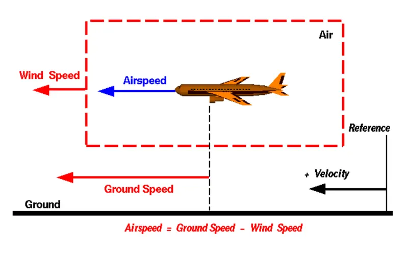
In general terms there are 2 different types of speed related to an aircraft, ground speed and airspeed.
While ground speed is the airplane’s speed relative to the surface of the Earth, airspeed – at least true airspeed – is its speed relative to the air it is flying in.
Below, I have explained the two types of speed in more detail, as well as talk about the four types of airspeed that are commonly used.
Airspeed vs. Ground Speed
As mentioned above, true airspeed is simply the speed at which an aircraft is moving relative to the air it is flying in. As such, it’s also the speed at which the air is flowing around the aircraft’s wings.
Ground speed, on the other hand, is the aircraft’s speed relative to the ground. One thing that should be noted here is that it’s its horizontal rather than vertical speed – an aircraft climbing completely vertically would have a ground speed of zero.
In other words, while airspeed determines whether there is enough airflow around an aircraft to make it fly,on the other hand ground speed determines how fast an aircraft will get to its destination.
Wind’s Effect on Ground Speed
The relationship between airspeed and ground speed is fairly simple. Ground speed is simply the sum of airspeed and wind speed.
If the aircraft is flying in the same direction as the wind is blowing, the aircraft experiences tailwind, and its ground speed is higher than its airspeed. On the other hand, if the wind is blowing against the direction the aircraft is traveling in, the aircraft experiences headwind, and its ground speed is lower than its airspeed.
Giving an example, imagine an aircraft that cruises at an airspeed of 500 miles per hour that has to cover a ground distance of 2,000 miles.
If there is no wind at all, then both the aircraft’s airspeed and ground speed would be the same 500 miles per hour, and the aircraft would reach its destination in four hours.
If there was a 100 miles per hour headwind – wind blowing against the aircraft’s direction of travel – the aircraft would still be traveling at an airspeed of 500 miles per hour. However, its ground speed would be just 400 miles per hour (100 miles per hour slower than its airspeed). And as such, it would take the aircraft five hours to reach its destinations.
Finally, if there was a 100 miles per hour tailwind – wind blowing in the same direction as the aircraft’s travel – the aircraft would still be traveling at an airspeed of 500 miles per hour, but its ground speed would be 100 miles faster. And, at 600 miles an hour, the aircraft would reach its destination in just three hours and twenty minutes.
The above is the reason why some flights go “out of their way” to avoid headwinds or catch tailwinds. And, why some flights might appear to be traveling at “supersonic speeds,” even though their airspeed – the speed that would actually matter in determining whether or not the flight truly is supersonic – is subsonic.
The Three Types of Airspeed
When I talked about airspeed earlier in this article, I was talking about true airspeed. However, pilots commonly use three different types of airspeed: indicated airspeed, calibrated airspeed, and true airspeed.
Indicated airspeed is an airspeed that is calculated directly off an aircraft’s pitot-static system. It’s the calculated off the aircraft’s dynamic pressure – the difference between its total pressure and static pressure.
The dynamic pressure depends not only on the aircraft’s speed, but also on the density of the air it is flying in. As such, the higher the aircraft flies – and the lower the air density as a result – the bigger the difference between indicated and true airspeed is.
Calibrated airspeed is indicated airspeed adjusted for a variety of errors.
Just as an example, one of the things it’s adjusted for is the flap position. The reason for that is that at different flap positions, air flows differently around the pitot-static system and affects the indicated airspeed readings.
True airspeed is, as has been mentioned numerous times in this article, the actual speed at which an aircraft is moving relative to the air it is traveling in. It’s calibrated airspeed adjusted for the the exact conditions (altitude, air temperature, etc.) that the aircraft is flying in.
Summary
For pilots, both airspeed and ground speed are very important. While the first of those helps them make sure they are flying fast enough to take off, not to stall, and so on, the second one helps them figure out how long it will take them to get from one place to another.
On the other hand, if you are a passenger, you will only need to be concerned about the ground speed as that will tell you how fast are you flying from your origin to your destination – how fast you will be able to get to your meeting, meet your relatives, or do whatever else the reason for your travel might be.
3. Why is it not recommended to use aircraft engine power to move it on the ground at Airport?
i. We are assuming passenger large commuter aircraft. Aircraft move using their own engine power all the time on the airport apron and taxiways under their own power to go towards runways and after landing taxi to their assigned gate.
The only time they use external assistance is to pushback from the gate. Large turbofan aircraft need help to reverse via a pushback tractor. The engines are turned on after the pushback is complete and the aircraft can move forward under It’s own power.
To be accurate, some aircraft can reverse using a variable pitch prop or thrust reversing on turbofans but generally reversing is done via pushback tractors. Blasting jet reversers blows debris In the crowded gate area creating foreign object damage hazard for adjacent aircraft, gate equipment or terminal waiting area glass windows.
Aircraft are designed to fly. When they’re going to spend more than 15 hours in the air, they need to perform as efficiently as possible. From getting the most power out of the engines to maximizing the lift from the wings, the main part of the design process is focused on the airborne aspect. However, it’s no good creating the perfect flying machine if you can’t get it to and from the terminal building. So, how do you get 200 tons of aircraft from the runway to the gate?
In order to save as much engine power as possible for its actual flight its very recommended to move it using external vehicle .
ii. Also during reverse thrusting which helps the aircraft move in reverse consumes lot of fuel,creates lot of noise & is also hazardous for people working nearby.
Hence it is very much recommended to use external vehicle power to move the aircraft(forwards & backwards) at airport.
4. How an aircraft is pushed to runway when its ready to take off ?
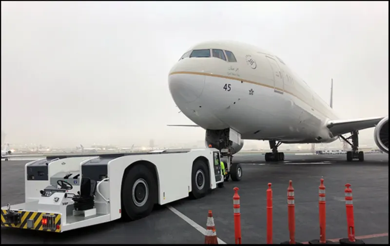
Large jetliner passenger aircraft are pushed away from the passenger loading gate by a tug. This is a machine with wheels, some form of power such as an internal combustion engine, or a battery. When the large aircraft is being pushed backwards, there is someone on each wing tip. They are looking out to make sure nothing will touch the aircraft. The whole idea is to avoid expensive crunching noises.
The noisy environment created by the aircraft engine power in case engine power is used to take it to the runway,results in hazardous environment for the personnel working at the gates and near runway areas
An airliner might be pushed backwards off the ramp, and onto a taxi way. Then the engines can start, the aircraft can proceed forward under its own power. A twin engine jet might not start the second engine until it is close to takeoff runway, clearance is certain.
A piston engine can run at idle power using only a small percentage of the fuel consumption used at operating power level. Turbine engines such as modern airliner turbo fan engine burn a lot of fuel once they are started. So, there is a lot of incentive to not run them until it is time to fly.
So both aircraft's engine power as well as through an external towing vehicle(powered by IC engine or electrically) can be used to push the aircraft to the runway But it's recommended not to use aircraft's engine power to push the aircraft to the runway as it would minimize the hazardous risks to the personell working near the runway and gates area created due to the high power of the aircraft engine as well as it would save the fuel and the overall fuel consumption efficiency of the aircraft so that the maximum engine power can be used during the flight of the aircraft.
5.Discussing take off power, tyre design, rolling resistance, tyre pressure, brake forces of an aircraft during landing.
Takeoff is the phase of flight in which an aerospace vehicle leaves the ground and becomes airborne. For aircraft traveling vertically, this is known as liftoff. For aircraft that take off horizontally, this usually involves starting with a transition from moving along the ground on a runway. For balloons, helicopters and some specialized fixed-wing aircraft (VTOL aircraft such as the Harrier and the Bell Boeing V22 Osprey), no runway is needed.
Takeoff power:
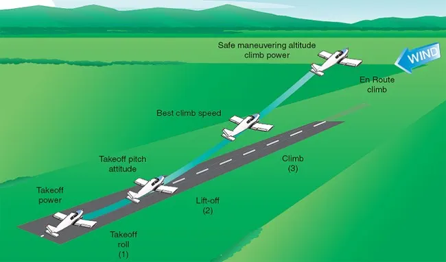
For light aircraft, usually full power is used during takeoff. Large transport category (airliner) aircraft may use a reduced power for takeoff, where less than full power is applied in order to prolong engine life, reduce maintenance costs and reduce noise emissions. In some emergency cases, the power used can then be increased to increase the aircraft's performance. Before takeoff, the engines, particularly piston engines, are routinely run up at high power to check for engine-related problems. The aircraft is permitted to accelerate to rotation speed (often referred to as Vr). The term rotation is used because the aircraft pivots around the axis of its main landing gear while still on the ground, usually because of gentle manipulation of the flight controls to make or facilitate this change in aircraft attitude (once proper air displacement occurs under / over the wings, an aircraft will lift off on its own; controls are to ease that in).
The nose is raised to a nominal 5°–15° nose up pitch attitude to increase lift from the wings and effect liftoff. For most aircraft, attempting a takeoff without a pitch-up would require cruise speeds while still on the runway.
Fixed-wing aircraft designed for high-speed operation (such as commercial jet aircraft) have difficulty generating enough lift at the low speeds encountered during takeoff. These are therefore fitted with high-lift devices, often including slats and usually flaps, which increase the camber and often area of the wing, making it more effective at low speed, thus creating more lift. These are deployed from the wing before takeoff, and retracted during the climb. They can also be deployed at other times, such as before landing.
The speeds needed for takeoff are relative to the motion of the air (indicated airspeed). A headwind will reduce the ground speed needed for takeoff, as there is a greater flow of air over the wings. Typical takeoff air speeds for jetliners are in the range of 240–285 km/h (130–154 kn; 149–177 mph). Light aircraft, such as a Cessna 150, take off at around 100 km/h (54 kn; 62 mph). Ultralights have even lower takeoff speeds. For a given aircraft, the takeoff speed is usually dependent on the aircraft weight; the heavier the weight, the greater the speed needed.[1] Some aircraft are specifically designed for short takeoff and landing (STOL), which they achieve by becoming airborne at very low speeds.
Tyre design:
Why are tyres important in an aircraft ?
When it comes to safety, tyres are one of the most important components of aircraft. They help to absorb the shock of landing and provide cushioning. It also provides the necessary traction for braking and stopping of an aircraft.
An aircraft tyre is designed to withstand extremely heavy loads while landing, take off, taxing, and parking. The number of wheels required for aircraft increases with the weight of the aircraft, as the weight of the aeroplane needs to be distributed more evenly.
A Boeing 737NG & 737MAX uses 6 wheels, Boeing 787 uses 10 wheels, Boeing 777 uses 14 wheels and Airbus A380 uses 22 wheels. Aircraft tyres work under extreme conditions, carrying up to 340 tons and accelerating at over 250 km/hour at takeoff, in addition to enduring varied environmental stress when in flight and taxiing.
Design and Construction of Aircraft tyre
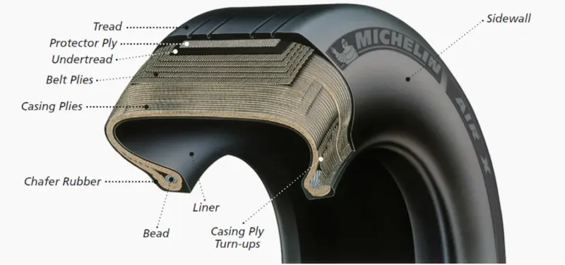
Carcass plies are used to form the tire. They are sometimes called casing plies. An aircraft tyre is constructed for the purpose it serves.
- They support the weight of an aircraft while it is on the ground.
- It also provides the necessary traction for braking and stopping of an aeroplane.
- Tyre also helps to absorb the shock of landing and provide cushioning the roughness of takeoff, roll-out, and taxi operations.
Unlike an automobile or truck tyre, it does not have to carry a load for a long period of continuous operation. However, an aircraft tyre absorbs the high impact loads of landing, and also it’s operating at high speeds for a short time when required.
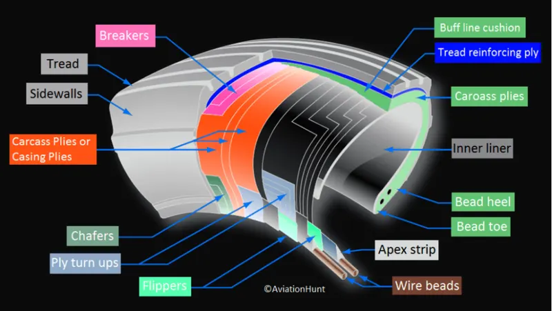
Now we will discuss some technical aspects of aircraft tyres ?
Retreading – Retreading is methods of restoring a worn tyre by renewing the tread area or by renewing the tread area plus one or both sidewalls. Repairs are included in the tyre retreading process.
Load Rating – Load rating is the maximum permissible load at a specified inflation pressure.
Ply Rating – Ply Rating is used to identify the maximum recommended load rating and inflation pressure for a specified tyre. It is an index of tyre strength.
Speed Rating – The speed rating is the maximum takeoff speed to which the tyre has been tested.
Skid Depth – Skid depth is the distance between the tread surface and the deepest groove as measured in the mould.
Aircraft tyres must have an approved speed and load rating and have sufficient clearance when retracted through landing gear to allow for tyre growth. Tyre growth is the increase in the size of the tyre due to centrifugal forces at high speed.
Aircraft tyres may be Tube-type or Tubeless
Tubeless tyres are more advantageous over tube-type. There is no longer the use of tube-type tyre in recent aviation. Nowadays all airliners are using tubeless tyres. Tubeless that are meant to be used without a tube has the word TUBELESS on the sidewall of the tyre.
Aircraft tyres may be Radial or Bias
Almost all airliners are using Radial tyre. Bias is an older design, and it’s mainly used for road vehicles. Radial tyres have the word RADIAL on the sidewall. Radial tires are more expensive than bias-ply tyres. Radial tires are in demand because of their lower life cycle cost and long term value.
Rolling resistance:
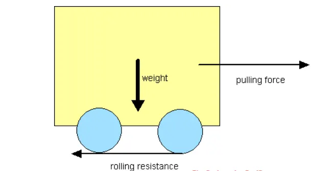
The rolling resistance can be expressed by the generic equation
Fr = c W (1)
where
Fr = rolling resistance or rolling friction (N, lbf)
c = rolling resistance coefficient - dimensionless (coefficient of rolling friction - CRF)
W = m ag
= normal force - or weight - of the body (N, lbf)
m = mass of body (kg, lb)
ag = acceleration of gravity (9.81 m/s2, 32.174 ft/s2)
Note that the rolling resistance coefficient - c - is influenced by different variables like wheel design, rolling surface, wheel dimensions and more.
Rolling Resistance
Rolling friction and rolling resistance
The force that resists the motion of a body rolling on a surface is called the rolling resistance or the rolling friction.
Note that the rolling resistance coefficient - c - is influenced by different variables like wheel design, rolling surface, wheel dimensions and more.
The rolling resistance can alternatively be expressed as
Fr = cl W / r (2)
where
cl = rolling resistance coefficient - dimension length (coefficient of rolling friction) (mm, in)
r = radius of wheel (mm, in)
Rolling Friction Coefficients
Some typical rolling coefficients:
| Rolling Resistance Coefficient | ||
|---|---|---|
| c | cl (mm) | |
| 0.001 - 0.002 | 0.5 | railroad steel wheels on steel rails |
| 0.001 | bicycle tire on wooden track | |
| 0.002 - 0.005 | low resistance tubeless tires | |
| 0.002 | bicycle tire on concrete | |
| 0.004 | bicycle tire on asphalt road | |
| 0.005 | dirty tram rails | |
| 0.006 - 0.01 | truck tire on asphalt | |
| 0.008 | bicycle tire on rough paved road | |
| 0.01 - 0.015 | ordinary car tires on concrete, new asphalt, cobbles small new | |
| 0.02 | car tires on tar or asphalt | |
| 0.02 | car tires on gravel - rolled new | |
| 0.03 | car tires on cobbles - large worn | |
| 0.04 - 0.08 | car tire on solid sand, gravel loose worn, soil medium hard | |
| 0.2 - 0.4 | car tire on loose sand | |
Rolling Coefficients Cars
The rolling coefficients for air filled tires on dry roads can be estimated
c = 0.005 + (1 / p) (0.01 + 0.0095 (v / 100)2) (3)
where
c = rolling coefficient
p = tire pressure (bar)
v = velocity (km/h)
Example - Wheel Pressure & Rolling Resistance Coefficient
The standard wheel pressure in a Tesla Model 3 is 2.9 bar (42 psi). The rolling friction coefficient at 90 km/h (56 mph) can be calculated from (3) as
c = 0.005 + (1 / (2.9 bar)) (0.01 + 0.0095 ((90 km/h) / 100)2)
= 0.011
Increasing the pressure to 3.5 bar reduces the rolling resitance coefficient to
c = 0.005 + (1 / (3.5 bar)) (0.01 + 0.0095 ((90 km/h) / 100)2)
= 0.010
- or
((0.011 - 0.10) / 0.011) 100% = 9%
Example - The Rolling Resistance of a Car on Asphalt
The rolling resistance for all four wheels in a car with total weight 1500 kg on asphalt with rolling friction coefficient 0.03 can be estimated with the generic equation 1 as
Fr = 0.03 (1500 kg) (9.81 m/s2)
= 441 N
= 0.44 kN
- compare car rolling resistance with car air resistance (drag)
The rolling resistance for one wheel can be calculated as
Fr = 0.03 (1500 kg / 4) (9.81 m/s2)
= 110 N
= 0.11 kN
Tyre pressure:
Aircraft tyres don't explode on landing because they are pumped & very strong !
ONE THING YOU almost never see when an airplane lands is a blowout. Think about that: Again and again, the tires hit tarmac at 170 miles per hour and bear the weight of a modest office building. And they nail it. Every time.
Aircraft tires are amazing when you think about it. The typical airliner tire can handle a 38-ton load. It can meet the ground 500 times before needing a re-tread, a refresh it can take on seven times in its life.
A Boeing 777 uses 14 tires, Airbus' A380 carries 22, and the enormous Antonov An-225 demands 32. The key to their remarkable durability is maximizing the air pressure, says Lee Bartholomew, lead test engineer for Michelin Aircraft Tires. The high-flying rubber is typically inflated to 200 psi, roughly six times what you put in an automobile tire, and the tires on an F-16 fighter are pumped to 320 psi. “It's really pressurized air that's so strong,” he says.
The tires themselves aren't terribly large--- a Boeing 737 rides on 27x7.75 R15 rubber. In English, that means it is 27 inches in diameter, 7.75 inches wide, and wrapped around a 15-inch wheel. The sidewalls aren't terribly thick, and the strength of the tire lies in the cords embedded below the tread, Bartholomew says. They're typically nylon, and more recently a variety known as aramid. Each layer of the casing contributes to its load bearing and air pressure resisting capabilities. Of course, tires can fail, especially when under-inflated or overloaded. Treads can come off and casings can blow out.
In the first moments after a plane touches down, the tires are skidding, not rolling. The airplane essentially drags them down the runway until their rotational velocity matches the velocity of the plane. That's why they smoke upon landing, and why Michelin uses grooves instead of the block patterns seen on your car's rubber---blocks would simply break off. (Most tire wear comes from this moment of contact---where the rubber meets the runway.) The stoutest tires are rated for speeds of up to 288 mph.
Brake forces on an aircraft during landing:
Aircraft brakes stop a moving aircraft by converting its kinetic energy to heat energy by means of friction between rotating and stationary discs located in brake assemblies in the wheels.
Brakes provide this critical stopping function during landings to enable airplanes to stop within the length of the runway. They also stop aircraft during rejected takeoff events, in which an attempted takeoff is canceled as the airplane is rolling down the runway before it lifts off from the ground due to engine failure, tire blowout, other system failure or direction from air traffic control.
Aircraft brakes also prevent motion of the aircraft when it is parked, limit its speed during taxiing and can even help steer the aircraft on the ground by applying different levels of braking force to the left- and right-side brakes.
Aircraft brakes work in conjunction with other brake mechanisms such as thrust reversers, air brakes and spoilers. Thrust reversers are surfaces that are deployed into the path of the jet blast from the engines to redirect propulsive thrust in a direction that opposes the motion of the aircraft. Air brakes and spoilers are flight control surfaces that create additional aerodynamic drag when deployed into the path of air flowing around the aircraft.
How aircraft brakes work
The most common type of brake used on aircraft is the disc brake. Disc brakes function by exploiting friction between rotating and stationary discs inside the brake.
Upon receiving a command signal to brake — from the pilot depressing a foot pedal or from the autobrake system — actuators in the brake move a piston to squeeze the discs together, generating a frictional force that slows the rotation of the wheel. The friction between the discs generates heat as the aircraft’s kinetic energy is converted to heat.In this function, the brakes act as a heat sink, absorbing tremendous amounts of heat as the aircraft sheds kinetic energy. During RTO stops, the temperature of carbon disc brakes can exceed 1,800° C.The discs are mounted on a carrier assembly consisting of a torque tube, which resists and transmits brake torque to the landing gear structure. Sandwiched together between the carrier assembly housing and a backing plate, the discs are arranged in an alternating pattern of rotors and stators. Notch and groove geometry around the circumference of each rotor fits into corresponding geometry in the wheel, keying the rotors to the wheel so that they rotate with it. The stators are keyed to the torque tube and are thus held stationary since the torque tube is connected to the axle and landing gear structure.
Cylindrical spaces within the carrier assembly hold actuator pistons. Braking occurs as piston force squeezes the discs together.
During each application of the brakes, disc material is worn away by frictional forces. A wear indicator in the form of a pin that protrudes out of the carrier assembly indicates the thickness of the stack of discs. Over hundreds of brake applications, material wears away and discs become thinner, requiring replacement following periodic maintenance intervals.
Brake design
The primary design considerations for aircraft brakes include the number of discs, the diameter of the discs and the material of the discs.
A major design point around which aircraft brakes are designed is the worst-case scenario of rejected takeoff (RTO) at the maximum rolling speed V1, known as the decision speed. Above V1, a takeoff could not be safely aborted without serious risk of the airplane failing to stop before the end of the runway. In this situation, the brakes need to absorb more energy than any other scenario.
To illustrate how much energy this is, consider an Airbus A380 — the world’s biggest passenger airplane — performing an RTO at V1. The maximum take-off weight of an A380 is 575,000 kg (1,267,658 lb) and its maximum V1 is around 170 knots (about 195 mph or 87 m/s). A rough estimate for the maximum energy that the A380’s 16 brakes need to dissipate during RTO can be obtained by calculating the kinetic energy of the aircraft (neglecting the effects of thrust reversers, air brakes, tailwinds, headwinds and runway slope).
Since kinetic energy (KE) is a function of mass (m) and velocity (v) according to the equation:
KE = ½mv2
The kinetic energy of the A380 during RTO is calculated as follows:
KE = 0.5 * 575,000 kg * (87.4556 m/s)2 = 2.2 x 10⁹ J = 2.2 GJ
2.2 GJ (gigajoules) is about the amount of energy an average cloud-to-ground lightning strike dissipates. It is also enough energy to power an 8 W LED light bulb (with light output equivalent to a 60 W light bulb) continuously for 8 years and 10 months.
To generate the necessary frictional forces and to handle this much energy within the length of a runway, large commercial transport aircraft typically require multiple discs per brake assembly and brakes on most, if not all, of their wheels.
For example, an A380 has 22 wheels distributed on five landing gear legs to support its massive weight: two nose wheels on a leg beneath the nose of the aircraft, eight wing wheels split between two legs that fold out from under the fuselage to support the left and right wings, and 12 body wheels split between two inboard landing gear legs under the fuselage. Sixteen of these wheels have brakes (four aft body wheels and the nose wheels are not braked).
The A380 uses Honeywell’s Carbenix brakes. Each of the aircraft’s 16 brake assemblies has five rotors made of Carbenix 4000 carbon-carbon composite. The brake assemblies are located within wheels made of 2014-T6 aluminum alloy and attached to the axle and landing gear structure, which is comprised of 300 M high-strength alloy steel, titanium and aluminum components.
Brake actuator type
Brake actuators perform the critical task of squeezing discs together to generate the frictional forces that convert the aircraft’s kinetic energy of motion into heat to stop the aircraft. Most brake actuators on commercial aircraft are hydraulic, although electrically powered electromechanical actuators have entered service as well; the brakes on both the Airbus A220 (formerly known as the Bombardier C-series) and the 787 are electromechanically actuated.
Hydraulic brakes are powered by the aircraft’s hydraulic system. A servo valve modulates the flow of hydraulic fluid to the hydraulic actuator to control the amount of braking force — the force with which the hydraulic cylinder presses the discs together.
Electric brakes are powered by the aircraft’s electric system. Electricity is converted to mechanical power in the brake’s electromechanical actuators. In these actuators, an electric motor drives gears to turn a ball screw and nut to apply force to press the brake discs together.
Redundancy is a necessary attribute built into aircraft braking systems due to the critical safety function that brakes provide. For example, the A380’s hydraulic brake system is powered by multiple separate 5,000 psi hydraulic systems. The set of brakes on the wing wheels and the set of brakes on the body wheels are attached to two separate hydraulic systems. The brake system is also supplied by a backup hydraulic system called the local electrohydraulic generation supply (LEHGS), which provides an alternate source of hydraulic power in the event of primary hydraulic system failure. The LEHGS generates hydraulic pressure with an electric motor-driven pump supplied by the aircraft’s electrical system.
The design for the 787’s electric brakes also features redundancy. With four independent electromechanical actuators per wheel, operation of the 787 is permissible with 100% braking function available even if one of the electric brake actuators (EBAs) fails. The modular nature of the EBAs enables easy, in-situ maintenance during which a failed EBA can be quickly swapped out for a new one.
Autobrakes and skid control
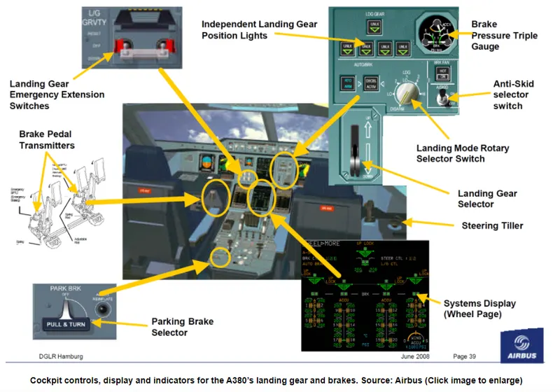
Modern commercial aircraft are equipped with an autobrake system that controls the deceleration of the aircraft by automatically optimizing the application of brake force independent of pilot operation of the brake pedals to minimize stopping distance, reduce pilot workload and smooth braking action.
Another common feature of aircraft brake systems is a skid control function. Similar to anti-lock brakes on an automobile, skid control systems prevent wheel lockup. They minimize stopping distance and prevent the negative effects of skidding on tires such as unnecessary tire wear and blowout. Skid control is accomplished by applying an optimal brake force that maximizes the coefficient of friction and remains just below the amount of force that would cause skidding. In one implementation, the proper force is arrived at by continuously sensing wheel speed and comparing it to a calculated aircraft velocity. The difference between the two values represents wheel slip and brake force is reduced if it rises above a specified value.
Part B:
6.
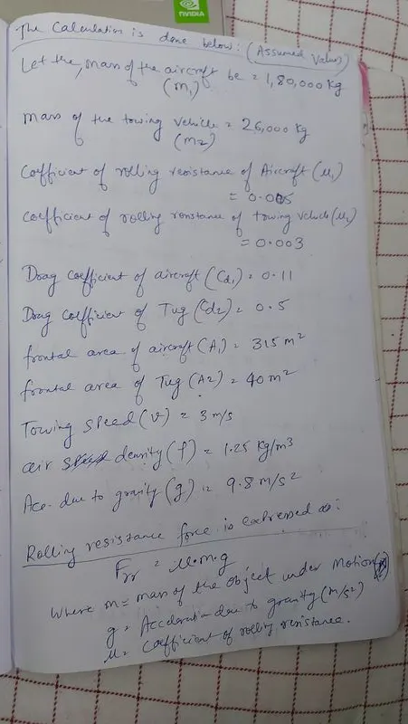
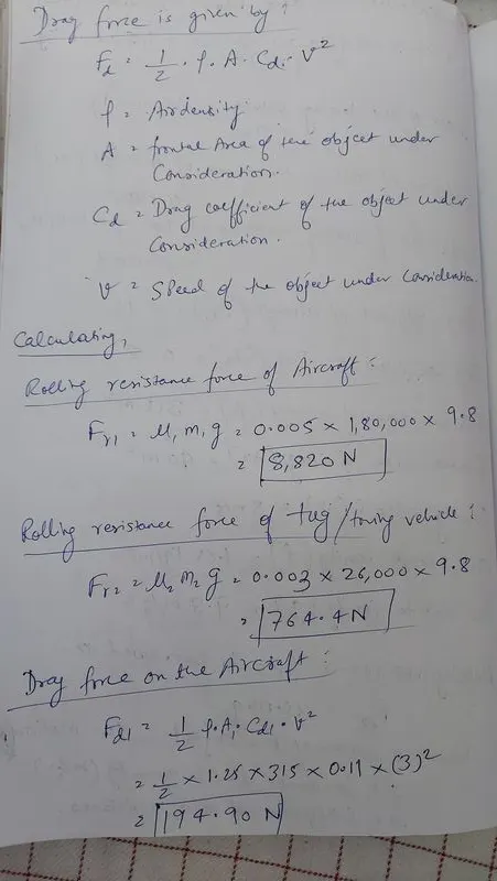
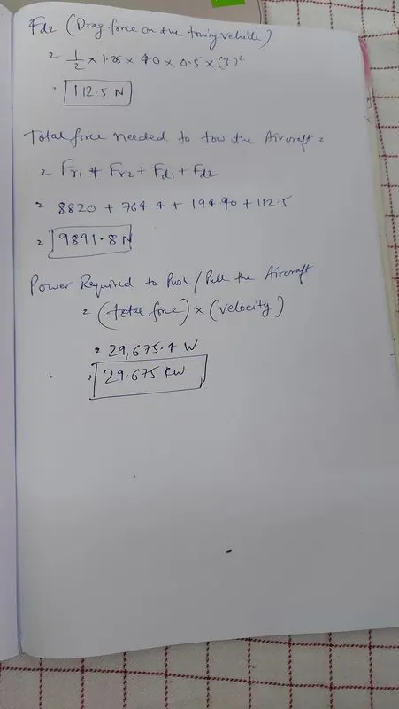
A. With necessary assumptions, calculating the force and power required to push / pull an aircraft by a towing vehicle.
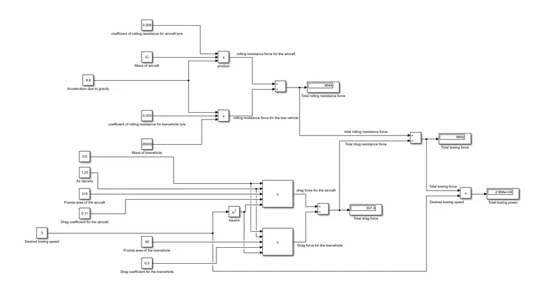
B. Simulink model for the above calculation of aircraft towing force & power:
7. A. Design an electric powertrain with type of motor, it’s power rating, and energy requirement to fulfill aircraft towing application in Simulink. Estimate the duty cycle range to control the aircraft speed from zero to highest. Make all required assumptions. Prepare a table of assumed parameters. Draw a block diagram of powertrain.
i will design a powertrain with the mimimum towing power needed as 29.6 KW(taken from the 6th challenge where with necessary assumptions i calculated the force & power needed to push/pull an aircraft)
To deliver a minimum 29.6 KW of power to tow the aircraft we will be needing an electric motor that supplies around 33KW of power as no motors have 100% efficiency.
Assuming the motor efficiency to be 90% it will deliver 29.7 KW of power to tow the aircraft which would be enough as per the calculations.
Batteries: six 80V Lead acid batteries,190 Ampere Hr batteries(6 hr rate),wired in series
Vehicle speed loaded: 6mph
Lift cradle capacity: 700 kg
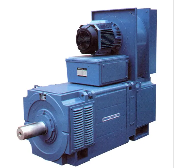
Vehicle drive: TT Electric - 33.3kW x 1030RPM - DC Shunt Wound Motor for 460V DC supply
160 Frame, Force Ventilated (IC06) to IP23.
Includes force cooling fan, 2 x thermistor temperature detection, washable intake filter and 60V/1000RPM Tacho-generator.
Minimum of 29.675 kW of power & 9.891 kN force is is needed to tow the aircraft as seen from calculation from the 6th challenge.
The tractive force(Fte) = T.G/r
Torque(T) needed to move the aircraft = (Fte.r)/(G.n) (where n is the efficiency of gear transmission,r is radius of the wheels,Fte is the tractive force needed to tow the aircraft & G is the gear ratio of the gear transmission)
In order to have a high torque at the driven gear(which will in turn rotate the wheels) the gear ratio(the ratio of number of driven gear teeth to the number of drive gear teeth) has to be high i.e the no. of teeths & the size of driven gear will be more than that of the driving gear.
Let us consider the gear ratio(G) to be 27,Radius of the tyre of towing vehicle as 30cm and efficiency of gear transmission to be 95% & calculate the torque needed to tow the aircraft
T= (9891.8 x 0.30)/(27 x 0.95) = 115.693 N-m is needed to tow the aircraft
Now calculating speed(w) at which the motor will deliver 115.693 N-m of torque
Power delivered by motor = Torque x speed(w)
speed(w) = Power delivered by motor / Torque = 29675 W/115.693 N-m = 256.497 rad/sec or 2449 RPM
motor has to run at 2449 RPM to deliver the required torque and power to tow the aircraft.
The input power given to the motor is assumed as 33KW that means the output power from the power converter (H-Bridge here) is 33 KW,assuming that the the input power given to the H-Bridge is 34KW & the H-Bridge used has an efficiency 97%.
The Lead acid battery used supplies 34KW of power to the power converter(efficiency of power converter is 97%),the output of the power converter is 33KW which is supplied to the motor,since the motor is 90% efficient ,the output power of motor is 29.7 KW,this output power when is supplied to the wheels through gear transmission & axle is 28.215KW as the efficiency of gearbox is 95%.
a 480V Lead acid battery supplies 34KW of power that means the current supplied by the battery is 34000W/480V = 71A.
Now calculating the efficiency of power converter(H-Bridge),for maximum duty cycle the output power of the power converter will be 33KW.
Maximum duty cycle = 33KW/34KW = 97% at which motor speed is 2449 RPM & Minimum duty cycle = 0% at which motor speed is 0 RPM.
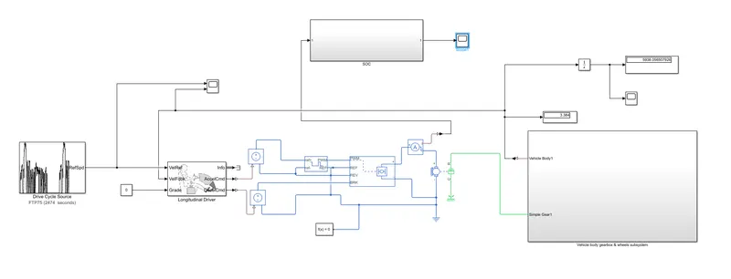
The simulink model for the electric powertrain is as below:
In the above simulink model the driver block is used to transmit the acceleration & deceleration signals and there are also input ports for velocity reference , velocity feedback & grade angle.
For a towing vehicle operation on a runway this grade angle will be 0 degrees.Velocity reference is taken from the drive cycle source block & velocity feedback is taken from the velocity of the vehicle body that comes from the vehicle body,gearbox & wheels subsystem.as per the difference between reference velocity & velocity feedback the acceleration command & deceleration commands will be generated by the driver.
Acc. command signal is given to the Controlled Voltage Source block & Dec command is given to the another Controlled Voltage Source1 block.
Controlled Voltage Source block is connected to the ref+ & ref- of the controlled PWM voltage block & Controlled Voltage Source1 block is connected to brake port of the H-Bridge block.
since both the Controlled PWM block and the H-bridge block are set in averaged mode so the motor will be operated at a duty cycle determined by the ratio = Voltage at the PWM port of the H-bridge block/PWM signal amplitude.
The motor speed input is given to the axle & wheels through the gear box(simple gear block) , the output of the Vehicle body gearbox & wheels subsystem is the velocity of the vehicle body through the Vehicle Body1 port. This velocity of vehicle body or the car is integrated to give distance covered.
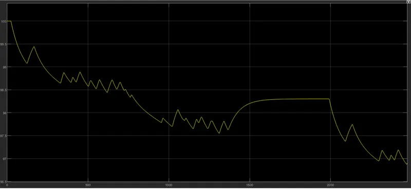
The current sensor will measure the motor current & update the battery state of charge calculations, the battery SOC reduces from 100% to 97% after 2474 seconds of model simulation & the velocity of the vehicle is 3m/s which is the recommended towing speed for the aircraft & the total distance that can be covered by the vehicle after 2474 seconds will be 5938.05 metres.The duty cycle at which the H-bridge converter is operated to run the vehicle at 3m/s speed is 30%.
The ports that are not used in the above model are not left unconnected,they are terminated using terminators.
Please find attached the excel sheet with designed parameters that are tuned to obtain the desired towing speed & battery SOC.For simulink model parameters refer the attached model "tow_vehicle.slx"
Parameters for electric powertrain for a aircraft towing vehicle Mass of the aircraft 1,80,000 kg Mass of the towing vehicle 26,000 kg coefficient of rolling resistance for the aircraft 0.005 coefficient of rolling resistance for the towing vehicle 0.003 Drag coefficient for the aircraft 0.11 Drag coefficient for the towing vehicle 0.5 Frontal area of the aircraft 315 m^2 Frontal area of the aircraft 40 m^2 Desired Towing speed for the aircraft 3 m/s air density considered 1.25 kg/m^3 Acceleration due to gravity 9.8 m/s^2 rolling resistance force for the aircraft 8820 N rolling resistance force for the towing vehicle 764.4 N drag force for the aircraft 194.90 N drag force for the towing vehicle 112.5 N Total force needed to tow the aircraft 9891.8 N Total power needed to push or pull the aircraft 29.675 KW Vehicle drive motor TT Electric - 33.3kW x 1030RPM - DC Shunt Wound Motor for 460V DC supply
160 Frame, Force Ventilated (IC06) to IP23.
Includes force cooling fan, 2 x thermistor temperature detection, washable intake filter and 60V/1000RPM Tacho-generator.
Efficiency of the motor = 90%Torque(T) needed to move the aircraft 115.693 N-m speed(w) at which the motor will deliver 115.693 N-m of torque 2449 RPM Efficiency of H-Bridge power converter 97% Input power to H-Bridge power converter 34 KW Output power from H-Bridge converter 33 KW Efficiency of the motor 90% Input power given to the motor 33 KW Output power from the motor 29.7 KW Efficiency of the gear transmission 95% input power to the gear transmission 29.7 KW Output power from the gear transmission to the axles 28.215 KW Maximum duty cycle 97% Minimum duty cycle 0% Motor speed at Maximum duty cycle 2449 RPM Motor speed at Minimum duty cycle 0 RPM