Project-1: Powertrain for aircraft in runways
AIM:
Powertrain for aircraft on the runway
OBJECTIVE:
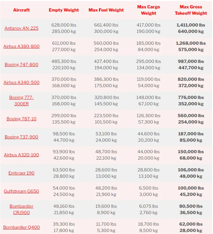
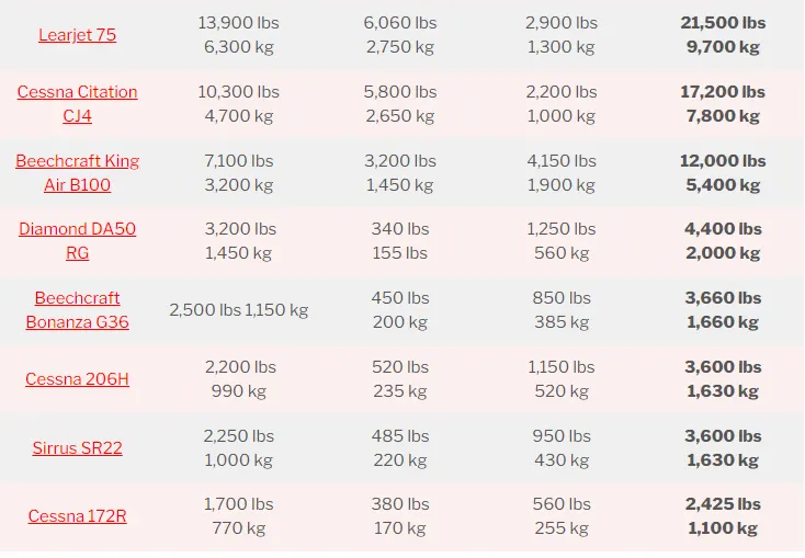
- Search and list out the total weight of various types of aircraft.
- Is there any difference between ground speed and airspeed?
- Why is it not recommended to use aircraft engine power to move it on the ground at the Airport?
- How an aircraft is pushed to the runway when it’s ready to take off?
- Learn about take-off power, tire design, rolling resistance, tyre pressure, brake forces when landing.
INTRODUCTION:
The maximum allowable weight for an aircraft is determined by design considerations by the aircraft’s manufacturer.
However, the maximum operational weight may be less than the maximum allowable weight due to such considerations as high-density altitude or high-drag field conditions caused by wet grass or water on the runway.
The maximum operational weight may also be limited by the departure or arrival airport’s runway length.
The structural weight limits are based on aircraft maximum structural capability and define the envelope for the CG charts. Aircraft structural weight capability is established during aircraft design and certification.
MAXIMUM DESIGN TAXI WEIGHT (MDTW OR MTW):
The maximum design taxi weight or maximum design ramp weight (MDRW) is the maximum certificated design weight for aircraft ground maneuvers is limited by aircraft strength and airworthiness requirements.
The difference between the maximum taxi/ramp weight and the maximum take-off weight (maximum taxi fuel allowance) depends on the size of the aircraft, the number of engines, APU operation, and engines/APU fuel consumption, and is typically assumed for 10 to 15 minutes allowance of taxi and run-up operations.
MAXIMUM DESIGN TAKEOFF WEIGHT (MDTOW OR MTOW):
The maximum design takeoff weight is the maximum certificated design weight for takeoff run as limited by aircraft strength and airworthiness requirements.
MAXIMUM DESIGN LANDING WEIGHT (MDLW OR MLW):
The Maximum design landing weight is the maximum certificated design weight for landing limited by aircraft strength and airworthiness requirements. It generally depends on the landing gear strength or the landing impact loads on certain parts of the wing structure.
MDLW < MDTOW < MDTW
MAXIMUM DESIGN ZERO-FUEL WEIGHT (MDZFW):
The maximum design zero-fuel weight is the maximum certificated design weight of the aircraft less all usable fuel and other specified usable agents as limited by aircraft strength and airworthiness requirements.
It is the maximum weight permitted before usable fuel and other specified usable fluids are loaded in specified sections of the airplane.
The weight difference between the MDTOW and the MDZFW may be utilized only for the addition of fuel.
Maximum payload = MDZFW – OEW
MINIMUM FLIGHT WEIGHT (MFW)
Minimum certificated weight for flight as limited by aircraft strength and airworthiness requirements.
SOLUTIONS:
- Total weight of various types of aircraft.
Before starting with the aircraft, let see some definitions related to aircrafts
DEFINITIONS
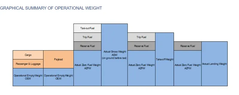
AIRCRAFT GROSS WEIGHT
The aircraft gross weight is the total aircraft weight at any moment during the flight or ground operation.
The aircraft’s gross weight decreases during the flight due to fuel and oil consumption. The aircraft’s gross weight may also vary during the flight due to payload dropping or in-flight refueling.
MANUFACTURER’S EMPTY WEIGHT (MEW)
Let’s start with the aircraft itself. An aircraft “as is” includes:
Airframe structure with all moving mechanical parts (fuselage, wings, flaps, gear, rudder, nacelle …)
- Power generation system (APU, main engines, power plant…)
- Systems (electrical, hydraulics, pneumatics, fuel flow system, instrument, navigation, air conditioning, anti-ice, fixed furnishing)
- Fixed equipment and services are considered an integral part of the aircraft
- Fixed ballast
- Closed system fluids
- Unused fuel only for small aircraft
All these items above form the Manufacturer’s Empty Weight (MEW).
This weight does not include:
- Fuel
- Oil, potable water
- Payload (Cargo, passenger, luggage)
- Removable equipment
- Customer-specific installations or operator items
OPERATIONAL EMPTY WEIGHT (OEW)
The MEW and the operator’s items are summed up to the Operational Empty Weight (OEW). The OEW is usually fixed for a specific aircraft and only gets changed during maintenance or operational changes.

OEW is the empty weight that is used in the flight simulator or the usual planning software
The operator’s items are:
- fluids necessary for aircraft operation (engine oil and coolant, water, unusable fuel)
- the water for galleys and lavatories
- aircraft documentation
- passenger seats (and the life vests)
- galley structure
- catering emergency equipment
- aircraft crew and their luggage.
- standard items necessary for full operation
ACTUAL ZERO FUEL WEIGHT (AZFW)
If we add the payload to the empty plane weight, we get the Actual Zero Fuel Weight (AZFW).

The payload includes:
- the passenger’s weight (the standard weights used defined by ICAO respectively)
- the passengers luggage’s weight
- the cargo weight
The assumed weights vary around some kg / lbs. depending on the number of seats available on the aircraft.
- a male passenger (incl. cabin luggage) weighs around 82kg (181 lbs.)
- a female passenger around 67kg (148 lbs.)
- a child around 50kg (110lbs.)
- an infant 16kg (35 lbs.).
These are statistical values but otherwise one would need to weigh every single passenger during check-in to get his exact weight. The additional payload consists of baggage and cargo (such as mail or goods).
ACTUAL GROSS WEIGHT (AGW)
In addition to the actual zero fuel weight, we add the fuel required for the flight and we get the Actual Gross Weight (AGW).

At that time, you should have calculated your total fuel for this flight.
The actual gross weight is the weight of aircraft ready for departure at the gate before push-back and start-up.
- Taxi-out fuel (at departure airfield)
- Trip fuel
- Holding
- Re-routing expectation
- regulation needs depending on your route arrival airfield
- fuel to join alternate airfield
- taxi-in fuel at the destination,
- final reserve
TAKE-OFF WEIGHT
Fuel burn during taxi operation to the departure runway reduces the gross weight. At the holding point, we have the Actual Take-off Weight (ATOW) which is used for take-off performance calculation.
The gross weight varies during flight. Fuel and oil consumption reduces the gross weight. Additionally, it may vary during the flight due to inflight refueling or payload dropping.

MAXIMUM DESIGN TAKEOFF WEIGHT (MDTOW)
The maximum takeoff weight (also known as the maximum brake-release weight) is the maximum weight authorized at brake release for takeoff, or at the start of the takeoff roll.
The maximum takeoff weight is always less than the maximum taxi/ramp weight to allow for fuel burned during taxi by the engines and the APU.
In operation, the maximum weight for takeoff may be limited to values less than the maximum takeoff weight due to aircraft performance, environmental conditions, airfield characteristics (takeoff field length, altitude), maximum tire speed and brake
At this weight, the subsequent addition of fuel will not result in the aircraft design strength being exceeded. The weight difference between the MTOW and the MZFW may be utilized only for the addition of fuel.
LANDING WEIGHT
With the calculation of fuel consumption during flight, we can calculate the Estimated Landing Weight (ELW) which is used for landing performance calculation at the destination.
Approaching your destination you use your current gross weight to determine the final approach speed. The gross weight now is the Actual Landing Weight (ALW).

Of course before landing, you never land without any fuel in reserve. The regulation is strict about fuel calculation for commercial air transportation including reserve fuel. Except in specific situations like re-routing, multiple holding, landing at alternate or technical problems, at landing, the aircraft shall still have the expected reserve fuel if there was no extra consumption.

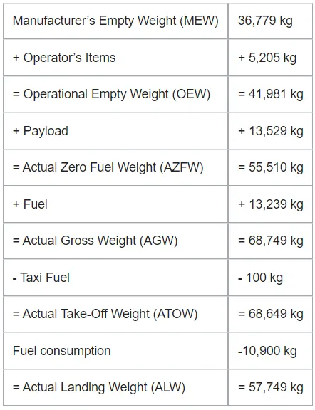
For example, here we have the Airbus a319
2. Difference between airspeed and ground speed.
Yes, there is a difference between the airspeed and ground speed.
While ground speed is the airplane’s speed relative to the surface of the Earth, airspeed – at least true airspeed – is its speed relative to the air it is flying in.
- True airspeed is simply the speed at which an aircraft is moving relative to the air it is flying in. As such, it’s also the speed at which the air is flowing around the aircraft’s wings.
- Ground speed, on the other hand, is the aircraft’s speed relative to the ground. One thing that should be noted here is that it’s its horizontal rather than vertical speed – an aircraft climbing completely vertically would have a ground speed of zero.
In other words, while airspeed is what determines whether there is enough airflow around an aircraft to make it fly, ground speed is what determines how fast an aircraft will get to its destination.
Ex: To simply explain them, we will take an example imagine an aircraft that cruises at an airspeed of 500 miles per hour that has to cover a ground distance of 2,000 miles.
If there is no wind at all, then both the aircraft’s airspeed and ground speed would be the same 500 miles per hour, and the aircraft would reach its destination in four hours.
If there was a 100 miles per hour headwind – wind blowing against the aircraft’s direction of travel – the aircraft would still be traveling at an airspeed of 500 miles per hour. However, its ground speed would be just 400 miles per hour (100 miles per hour slower than its airspeed). And as such, it would take the aircraft five hours to reach its destinations.
Finally, if there was a 100 miles per hour tailwind – wind blowing in the same direction as the aircraft’s travel – the aircraft would still be traveling at an airspeed of 500 miles per hour, but its ground speed would be 100 miles faster. And, at 600 miles an hour, the aircraft would reach its destination in just three hours and twenty minutes.
However, pilots commonly use three different types of airspeed: indicated airspeed, calibrated airspeed, and true airspeed.
Indicated airspeed is an airspeed that is calculated directly off an aircraft’s pitot-static system. It’s calculated off the aircraft’s dynamic pressure – the difference between its total pressure and static pressure.
The dynamic pressure depends not only on the aircraft’s speed but also on the density of the air it is flying in. As such, the higher the aircraft flies – and the lower the air density as a result – the bigger the difference between indicated and true airspeed is.
Calibrated airspeed is indicated airspeed adjusted for a variety of errors.
Just as an example, one of the things it’s adjusted for is the flap position. The reason for that is that at different flap positions, air flows differently around the pitot-static system and affects the indicated airspeed readings.
True airspeed is, as has been mentioned numerous times in this article, the actual speed at which an aircraft is moving relative to the air it is traveling in. Its calibrated airspeed is adjusted for the exact conditions (altitude, air temperature, etc.) that the aircraft is flying in.
3.Why is it not recommended to use aircraft engine power to move it on the ground at the Airport?
The movement of an aircraft on the ground under its own power is called Taxiing. But to move the aircraft from hanger to th
runway, the term used is the taxiways.
Although many aircraft are capable of moving in backward using reverse thrust, as a result, the jet blast or prop wash might caus
damage to the terminal building or equipment
Taxiing is the movement of an aircraft on the ground, under its own power, in contrast to towing or pushback where the aircraft is
moved by a tug. The aircraft usually moves on wheels, but the term also includes aircraft with skis or floats (for water-based
travel).
An airplane uses taxiways to taxi from one place on an airport to another; for example, when moving from a hangar to the
runway. The term "taxiing" is not used for the accelerating run along a runway prior to takeoff, or the decelerating run immediately
after landing, which are called the takeoff roll and landing rollout, respectively.
Generally aircrafts move with the help of Engine power on the ground at airport. The difference being that the engine power is not used at its full performance as obtained during the flight of the aircraft. The engine is operated under throttle 1 condition which uses engine power to obtain less speed. Sometimes it is not recommended to use the engine power to move the aircraft
on the ground at Airport. There are multiple reasons for this one of which is that there are a lot of things as well as airport crew
members surrounding the aircraft. If the aircraft uses its engine power in such an environment, the engine turbine or fan may suck or throw the surrounding objects, trash or even human beings which are accidental.
The air intake of a jet engine is powerful enough to suck in a human body. Even at a distance, the jet engine suction is strong enough to devour loose debris e.g., rags, bolts, paper, stones, catering foils, plastic cups and bags. All these will damage the jet engine. In case of Jet exhaust, the temperatures of the exhaust can severely burn the skin of a person standing too close. The jet blast or prop wash can exceed 100 mph and is capable of moving or toppling heavy persons or equipment. Other reasons being the noise of the engine which are at very high decibels as well as the fumes emitted by the burning of the fuel, the fuel consumption of an aircraft and also the risk of damage to the engine due to foreign objects.
4.How an aircraft is pushed to the runway when it’s ready to take off?
Aircraft is pushed back from the airport gate by vehicles called tugs or tractors. This is called Pushback. The tug might be direct attached to the plane's nose gear with a tow bar, or could be a "wheel-lift" tug. These tugs cradle the nose gear, then lift it u
before moving the plane. That gives the tug driver control over the plane's direction during pushback. New taxi technologies are appearing, like pilot-controlled tugs, and electric motors mounted to the plane's landing gear. Both promise to save fuel an
reduce airport noise
Pushback – In aviation, pushback is an airport procedure during which an aircraft is pushed backwards away from an airport gate by external power. Pushbacks are carried out by special, low-profile vehicles called pushback tractors or tugs. Although many
aircraft are capable of moving themselves backwards on the ground using reverse thrust (a procedure referred to as a power back), the resulting jet blast or prop wash might cause damage to the terminal building or equipment. Engines close to the ground may
also blow sand and debris forward and then suck them into the engine, causing damage to the engine. A pushback is therefore the preferred method to move the aircraft away from the gate. Closer to departure, an aircraft tug will park right in front of the
nose wheel. The tug might be directly attached to the plane's nose gear with a tow bar, or could be a wheel-lift tug. These tugs cradle the nose gear, then lift it up before moving the plane. That gives the tug driver control over the plane's direction during
pushback. New taxi technologies are appearing, like pilot-controlled tugs, and electric motors mounted to the plane's landing gear. Both promise to save fuel, and reduce airport noise. When the aircraft is stopped, the brakes of the towing vehicle alone
should not be relied upon to stop the aircraft. The man in the cockpit should coordinate the use of the aircraft brakes with those of the towing vehicle.
5. Explain about take-off power, tire design, rolling resistance, tyre pressure, brake forces when landing.
Take Off Performance:
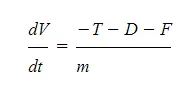
Take off performance can be predicted using a simple measure of the acceleration of the aircraft along the runway based on force equilibrium.
The forces involved will be,
T – Thrust of propulsion system pushing aircraft along runway.
D – Aerodynamic Drag of vehicle resisting the aircraft motion.
F – Rolling resistance friction due to the contact of wheels or skids on the ground.
During take-off run the imbalance in these forces will produce an acceleration along the runway.
`(dV)/dt = (T−D−F)/ m`
where dV/dt is the acceleration along the runway and m is the mass of the vehicle.
Rotation Velocity, VR
The procedure for take-off will be that the vehicle will accelerate until it reaches a safe initial flying speed. The pilot can then rotate the vehicle to an attitude to produce climb lift and it will ascend from the ground. The determination of this safe flying speed or rotation speed, VR, is a critical factor in determining take-off performance.
Take-off rules vary slightly depending on the aircraft category. Small commuter aircraft should be considered as meeting FAR 23 rules, transport category aircraft should comply with FAR 25 rules.
Small commuter aircraft :
For safety reasons VR is usually determined as being 1.1 × VSTALL or 1.05 × VMIN CONTROL which ever is greater.
Stall speed, VSTALL, is the lowest speed that the aircraft can be flown before the airflow starts to separate from wings as the angle of attack becomes too great. The wing is assumed in this case to be in take-off configuration or "clean".
It can be calculated based on knowledge of the aircraft take-off configuration and hence the maximum achievable lift coefficient CL(max). As shown in the previous section , to maintain level flight the lift produced must equal the weight, hence the stall speed can be calculated as,
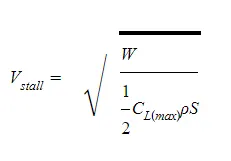
Minimum control speed, VMC is a more complex calculation and requires knowledge of the stall characteristics of the tailplane and elevator. For conventional aircraft there is only a small difference between VR calculations based on stall speed or minimum control speed.
As well as rotation speed there are other safety considerations as shown in the following Figure.
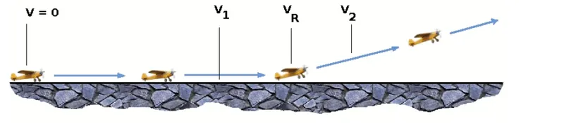
V1- Abort decision speed. Below this speed the take-off can be safely aborted. After this there will not be sufficient runway length to allow the aircraft to decelerate to a stop.
V2 – Safe climb speed. V2 must be no less than 1.2 * Vstall. Below this speed aircraft cannot attain sufficient climb rate.
Thrust
The thrust of gas turbine or turbofan engines will be relatively constant during take-off. A good assumption is to use the manufacturer's values for maximum static thrust for take-off calculations.
The thrust of a propeller driven aircraft can be found from the given shaft horsepower data for the engine and the use of the equations using propeller efficiency given in the previous section.
`T=(P_(shaft)×η)/V`
It is critical to correctly estimate the propeller efficiency for the particular aircraft velocity along the runway. At V=0 the efficiency is 0 so the above equation makes no sense. At V=VR the efficiency will be in the range 50% to 80% depending on the type of propeller system used and the thrust value at this point will be easy to obtain. In practice, the thrust obtained throughout the take-off roll is roughly constant so this end point value is a good approximation from V=0 to V=VR
Drag
The resistance to motion due to the air viscosity will give a drag of
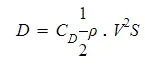
where CD can be considered constant and calculated using the formula shown in the previous section
Although Drag Coefficient is constant, Drag will increase in proportion to the square of velocity.
Tyre design :
Tyre :
Carcass plies are used to form the tire. They are sometimes called casing plies. An aircraft tyre is constructed for the purpose it serves.
- They support the weight of an aircraft while it is on the ground.
- It also provides the necessary traction for braking and stopping of an aeroplane.
- Tyre also helps to absorb the shock of landing and provide cushioning the roughness of takeoff, roll-out, and taxi operations.
Unlike an automobile or truck tyre, it does not have to carry a load for a long period of continuous operation. However, an aircraft tyre absorbs the high impact loads of landing, and also it’s operating at high speeds for a short time when required.
Some technical aspects of tyre :
Retreading – Retreading is methods of restoring a worn tyre by renewing the tread area or by renewing the tread area plus one or both sidewalls. Repairs are included in the tyre retreading process.
Load Rating – Load rating is the maximum permissible load at a specified inflation pressure
Ply Rating – Ply Rating is used to identify the maximum recommended load rating and inflation pressure for a specified tyre. It is an index of tyre strength.
Speed Rating – The speed rating is the maximum takeoff speed to which the tyre has been tested.
Skid Depth – Skid depth is the distance between the tread surface and the deepest groove as measured in the mould.
Aircraft tyres must have an approved speed and load rating and have sufficient clearance when retracted through landing gear to allow for tyre growth. Tyre growth is the increase in the size of the tyre due to centrifugal forces at high speed.
Yes, Today’s tyres are conductive. Aircraft tyres are manufactured with tread rubber with conducting compounds to permit earthing of static charges.
In early days when tyres were not sufficiently conductive, aircraft used to have a conductive strip hanging down from the axle of the landing gear. Upon landing, this strip would be the first part of the aircraft to touch the earth. This discharges any static electricity accumulated on the outer surfaces of the aircraft. Now you don’t see them anymore.
What is the purpose of Chines in aviation tyre
Chines are also called deflectors. Chine tyre used on the nose wheel of aircraft, specially fuselage-mounted jet engines. It diverts runway water away from the engine inlets.
Chines are circumferential protrusions that are moulded into the sidewall of nose tyres that deflect water sideways to help reduce excess water ingestion into the engines. Tyres may have chines on one or both sides, depending on the number of nose tyres on the aircraft.
Tyre Types
Based on the type of plies used the tyres can be:
- Radial ply tires - these tyres feature a flexible casing which is constructed of rubber-coated ply cords which extend around the beads and are substantially at 90° to the centerline of the tread. The casing is stabilized by an essentially inextensible circumferential belt.
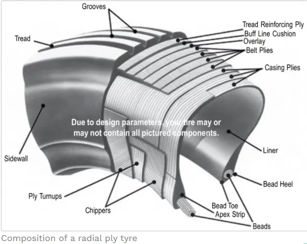
- Bias ply tires - these tyres feature a casing which is constructed of alternate layers of rubber-coated ply cords which extend around the beads and are at alternate angles substantially less than 90° to the center line of the tread.
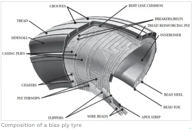
Based on the method for containing the inflation gas the tyres can be:
- Tube-type tyres - these require tubes for inflation retention.
- Tubeless tyres - these do not require tubes. They are constructed with an innerliner (integral rubber lining that is engineered to prevent the diffusion of the inflation gas into the casing.).
Some more details about the tyre handling and maintenance can be found in the link provided in the references .
Rolling resistance :
The friction between aircraft and runway will be proportional to the normal force exerted by the aircraft on the runway.
`F=μ(W−L)`
The normal force will be the difference between Weight of aircraft and Lift, the friction coefficient will be typically of a magnitude of 0.02 for a standard tarmac runway.
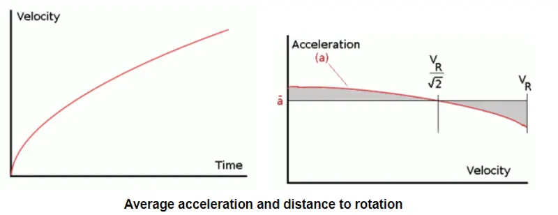
The rate of change of velocity can be predicted at any point on the take-off roll by substituting results for T, D and F into the initial equation for dV/dt. The subsequent velocity at any point can be found by integrating this resulting equation and the distance traveled found by then integrating the velocity.
Typically acceleration will be dominated by the drag component as thrust, weight and friction are relatively constant during this period. This leads to the result shown where acceleration is inversely proportional to velocity squared.
Due to the quadratic nature of acceleration change, an average value, `((dv)/dt)_(avg)= overlinea` can be used for the take-off run. This average acceleration can be found at the point where,
`V=V_R/root_2`
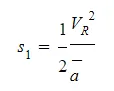
This average acceleration can be used to simplify calculations and the take-off run can be calculated as an equivalent constant acceleration over the complete period of time (tR) taken to get from 0 to VR. For a constant acceleration take-off calculation,

Rearranging leads to a relatively simple calculation to predict the distance to rotation point.
Tyre Pressure: Aircraft tires generally operate at high pressures, up to 200 psi (14 bar; 1,400 kPa) for airliners, and even higher for business jets. Tests of airliner aircraft tires have shown that they are able to sustain pressures of a maximum of 800 psi (55 bar; 5,500kPa) before bursting. During the tests, the tires have to be filled with water, to prevent the test room from being blown apart by the energy that would be released by gas when the tire bursts. Aircraft tires are usually inflated with nitrogen to minimize expansion and contraction from extreme changes in ambient temperature and pressure experienced during flight. Dry nitrogen expands at the same rate as other dry atmospheric gases (normal air is about 80% nitrogen), but common compressed air sources may contain moisture, which increases the expansion rate with temperature. The requirement that an inert gas, such as nitrogen, be used instead of air for inflation of tires on certain transport category airplanes was prompted by at least three cases in which the oxygen in air-filled tires had combined with volatile gases given off by a severely overheated tire and exploded upon reaching autoignition temperature. The use of inert gas for tire inflation eliminates the possibility of a tire explosion.
Brake force: One of the effective parameters influencing landing run is the brake force, while it is ineffective
during take-off operation.
The airspeed during the approach is decreased by increasing the angle of attack, but airspeed during ground roll is decreased by
applying brakes. The mechanical brakes present at the wheels are of two common kinds; drum brakes and disc brakes. Drum
brakes usually reside inside the wheel, which reduces their frontal area and, if mounted on retractable landing gear, makes them a
possible solution for space-claim issues in thin wing.
.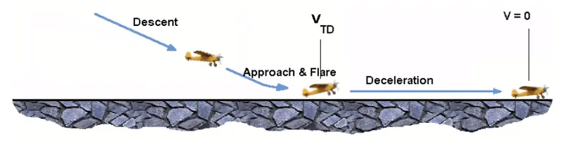
The touch-down velocity should be approximately the stall speed of the aircraft in landing configuration. This will be achieved by a pitch maneuver during the flare portion of the approach which increases drag and decelerates the aircraft to minimum flying speed.
The deceleration on the landing roll from VTD to V0 will be accomplished by braking and reverse thrust. This can be solved by the average acceleration approach that was used to estimate the take-off roll.
The negative acceleration or deceleration value will be based on the friction coefficient for maximum braking and the value of reverse thrust (if available)
Part B:
1. Calculate the force and power required to push/pull an aircraft by a towing vehicle.
Assumed data:
Here we will take the example of the Boeing 737
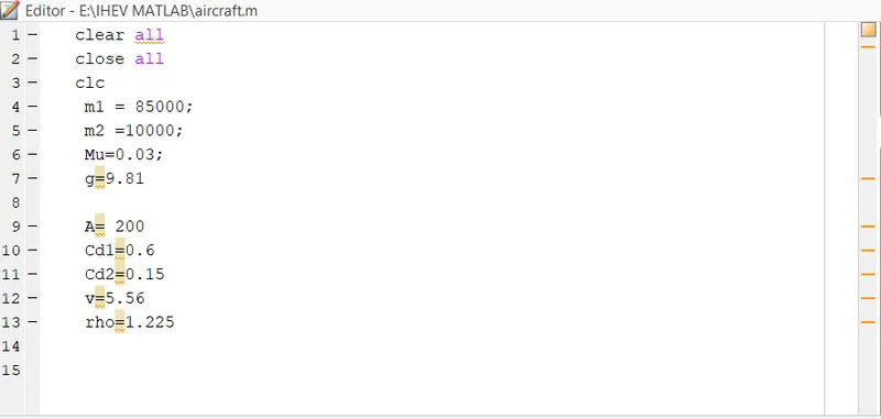
- Mass(gross weight)m1= 85000 kg
- Mass of the Towing Vehicle(m2)= 10000kg
- Coefficient of rolling resistance (dry concrete(`mu_r`)= 0.03,
- Frontal Area of the Vehicle (A)=`200m^2`
- Drag coefficient of an aircraft(`C_d1`)= 0.6,
- Drag coefficient of a Towing Vehicle(`C_d2`)= 0.15,
- Density of air(`rho`)= 1.225
- Gravity (g )= `9.81 m/s^2`
- Speed of an aircraft = 20kmph = 5.556 m/sec,
Calculations:
- Rolling Resistance Force:
For the Aircraft:
`F1=mu_r*m1*g`
= 0.03*85000*9.81
=25015.5 N
For the Towing Vehicle:
`F2=mu_r*m2*g`
=0.03*10000*9.81
= 2943 N
Now,
Total rolling resistance `(F_r)`= F1+F2
= 27958.5 N
- Tractive force :
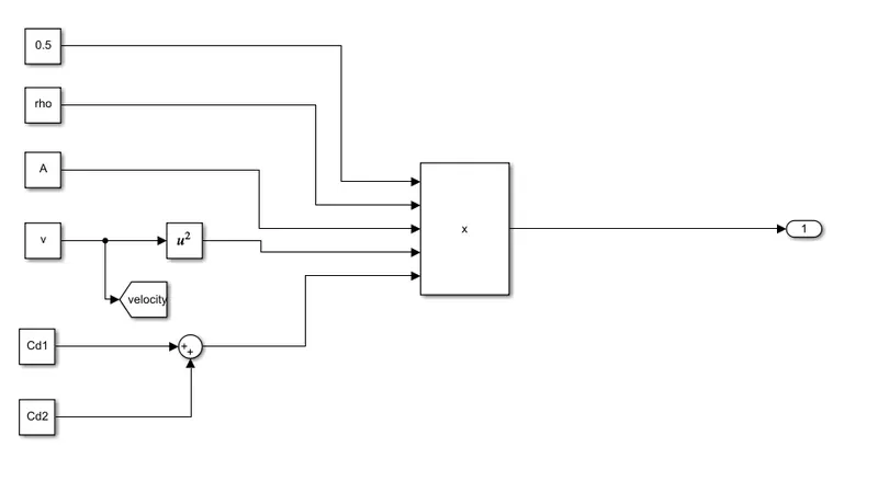
`F_t= 0.5*rho*A*V^2*(C_d1+C_c2)`
=0.5 *1.225*200*5.5*5.5 *(0.6+0.15)
= 2840.18 N
- Total force for towing the vehicle = `F_r+F_t`
= 27958.5+2840.18
= 30798.5 N
Therfore,
- Power required = F*v
= 30798.5*5.556
= 171.2 KW
The Force and Power of the Towing vehicle carrying the Aircraft are 30.7 KN and 171.2 KW respectively.
Develop the model for the calculated force and power using Simulink:
Model:
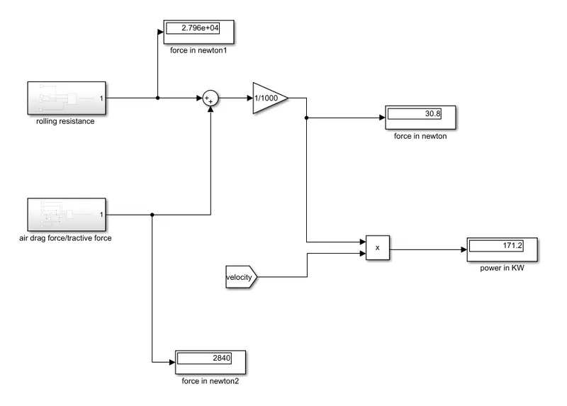
explanation :
- To create the Simulink model, we have created two systems one is rolling resistance and another is air drag force.
- All the values obtained from above were written in the Matlab program.
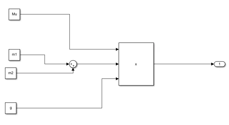
- Inside the rolling resistance block, we used constant blocks where input is taken from the base workspace, addition where both vehicle's mass is added and product block was the product of mass, friction and gravity. Output is taken outside using goto block.The same procedure is followed to obtain the tractive force.
- Then the output of these two subsystem is added to get the total force required which is first divided by 1000 using gain block to get value in kilo-newton.
- Later, the output force is multiplied with the Velocity to obtain the power required,
2. Design an electric powertrain with the type of motor, its power rating, and energy requirement to fulfill aircraft towing application in Simulink. Estimate the duty cycle range to control the aircraft speed from zero to highest. Make all required assumptions. Prepare a table of assumed parameters. Draw a block diagram of the powertrain.
Here taking all the reference values from the above calculations
The force required to push/pull the aircraft = 30.7 KN
Required Power = 171.2 KW
Now,
assuming tires size as 18*25 inches
R=25 inches =0.635 m
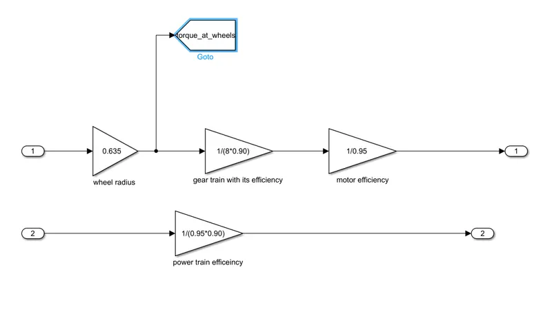
∴ The torque required at wheels = `F*R`
= 30798.5*0.635
=19.55 KN
To calculate the motor Torque, there will be a gear arrangement that will transmit the power to wheels and that assembly efficiency to around 90%
This gear arrangement will be increasing and reducing the torque based on the number of teeth on wheels. Assuming gear ratio to be 8
∴ Motor Torque = `T/( Gear ratio*efficiency`
= 19.55/8*0.90
= 2.77KN
That means the output from the motor shall be greater than or equal to 2.7KN
but we have to consider the efficiency of the motor also, let assume 95%
then motor torque = 2.7/0.95
= 2.84 KN
So, the motor minimum input needed considering all the efficiency of the system is
= 171.2/0.90*0.95
= 200 kW
Duty cycle :
To obtain the duty cycle first, we need to know how much energy is spent/needed in this towing operation.
Considering the towing operation time as 10 mins = 0.16 hrs
Energy = 200*0.16
= 32 kWh
So we need a higher battery capacity for a longer duration. Say a 250kW battery pack
now, the duty cycle can be
d= output power/ input power
= 200/250
= 0.80
i.e 80% duty cycle
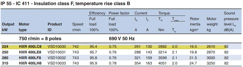
Based on the above calculations the motor specifications:
224 kW 3 phase induction motor
F type insulation
690V/50Hz,
Rated torque = 2882 Nm
Breakdown torque = 2.2* rated torque
Simulink model :
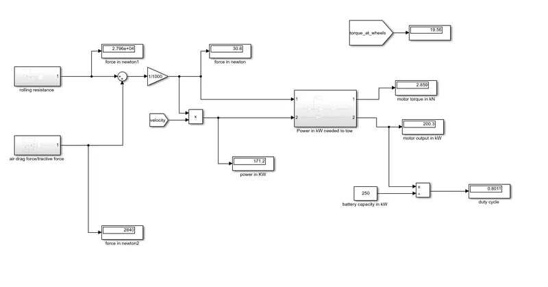
Design the parameters in excel sheet.
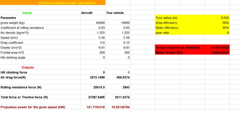
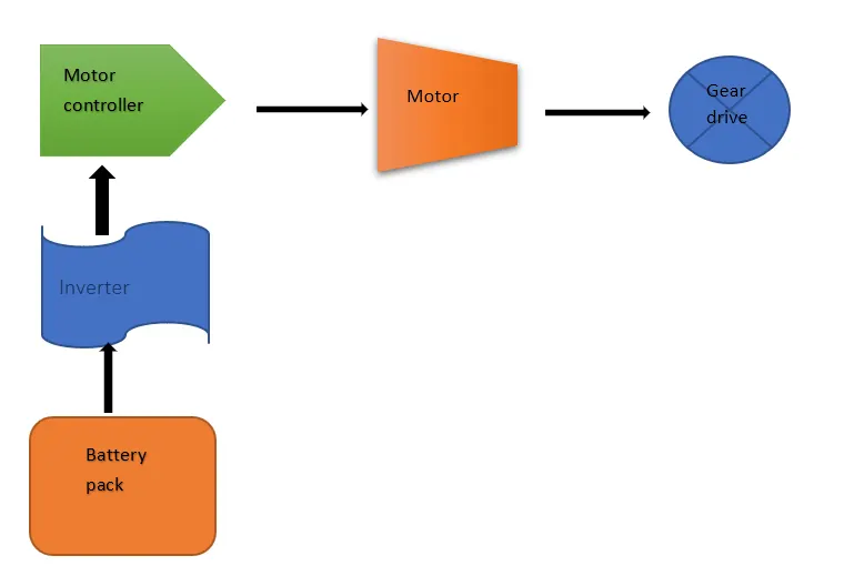
`
References :
https://pilotteacher.com/how-much-do-airplanes-weigh-with-20-examples/
https://mediawiki.ivao.aero/index.php?title=Standard_aircraft_weight
https://www.skybrary.aero/index.php/Aircraft_Tyre_Maintenance
https://www.aircraftsystemstech.com/p/aircraft-tires-and-tubes-aircraft-tires.html
http://www.aerodynamics4students.com/aircraft-performance/take-off-and-landing.php
https://thepointsguy.com/guide/how-pilots-move-a-plane-around-on-the-ground/
https://www.boeing.com/commercial/aeromagazine/aero_06/textonly/s02txt.html
https://people.ucalgary.ca/~aknigh/electrical_machines/induction/im_trq_speed.html