Project-1: Powertrain for aircraft in runways
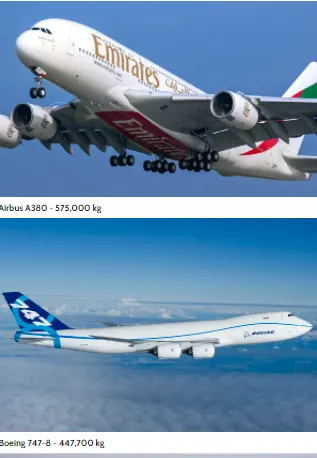
1. Search and list out the total weight of various types of aircrafts.
The aircraft gross weight (also known as the all-up weight and abbreviated AUW) is the total aircraft weight at any moment during the flight or ground operation.
An aircraft's gross weight will decrease during a flight due to fuel and oil consumption. An aircraft's gross weight may also vary during a flight due to payload dropping or in flight refueling.
At the moment of releasing its brakes, the gross weight of an aircraft is equal to its takeoff weight. During flight, an aircraft's gross weight is referred to as the en-route weight or in-flight weight.
Maximum design taxi weight (MDTW)
The maximum design taxi weight (also known as the maximum design ramp weight (MDRW)) is the maximum weight certificated for aircraft manoeuvring on the ground (taxiing or towing) as limited by aircraft strength and airworthiness requirements.
Maximum design takeoff weight (MDTOW)
Is the maximum certificated design weight when the brakes are released for takeoff and is the greatest weight for which compliance with the relevant structural and engineering requirements has been demonstrated by the manufacturer.
Maximum design landing weight (MDLW)
The maximum certificated design weight at which the aircraft meets the appropriate landing certification requirements. It generally depends on the landing gear strength or the landing impact loads on certain parts of the wing structure.
The MDLW must not exceed the MDTOW.
The maximum landing weight is typically designed for 10 feet per second (600 feet per minute) sink rate at touch down with no structural damage.
Maximum design zero-fuel weight (MDZFW)
The maximum certificated design weight of the aircraft less all usable fuel and other specified usable agents (engine injection fluid, and other consumable propulsion agents). It is the maximum weight permitted before usable fuel and other specified usable fluids are loaded in specified sections of the airplane. The MDZFW is limited by strength and airworthiness requirements. At this weight, the subsequent addition of fuel will not result in the aircraft design strength being exceeded. The weight difference between the MDTOW and the MDZFW may be utilised only for the addition of fuel.
Minimum flight weight (MFW)
Minimum certificated weight for flight as limited by aircraft strength and airworthiness requirements.
Types of aircraft
There are a number of ways to identify aircraft by type. The primary distinction is between those that are lighter than air and those that are heavier than air.
Lighter-than-air
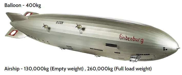
Aircraft such as ballons, nonrigid airships, and dirigibles are designed to contain within their structure a sufficient volume that, when filled with a gas lighter than air (heated air, hydrogen, or helium), displaces the surrounding ambient air and floats, just as a cork does on the water. Balloons are not steerable and drift with the wind. Nonrigid airships, which have enjoyed a rebirth of use and interest, do not have a rigid structure but have a defined aerodynamic shape, which contains cells filled with the lifting agent. They have a source of propulsion and can be controlled in all three axes of flight. Dirigibles are no longer in use, but they were lighter-than-air craft with a rigid internal structure, which was usually very large, and they were capable of relatively high speeds. It proved impossible to construct dirigibles of sufficient strength to withstand routine operation under all weather conditions, and most suffered disaster, either breaking up in a storm, as with the U.S. craft Shenandoah, Akron, and Macon, or through ignition of the hydrogen, as with the German in 1937.
heavier than air
This type of aircraft must have a power source to provide the thrust necessary to obtain lift. Simple heavier-than-air craft include kites. These are usually a flat-surfaced structure, often with a stabilizing “tail,” attached by a bridle to a string that is held in place on the ground. Lift is provided by the reaction of the string-restrained surface to the wind.
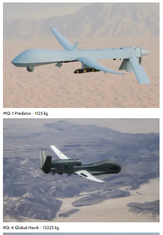
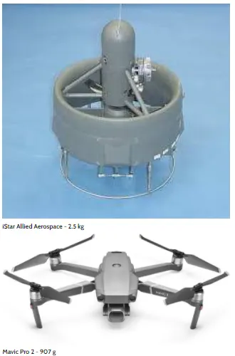
Another type of unmanned aircraft is the unmanned aerial vehicle (UAV), commonly called drones or sometimes remotely piloted vehicles (RPVs). These aircraft are radio-controlled from the air or the ground and are used for scientific and military purpose
Hang gliders are aircraft of various configurations in which the pilot is suspended beneath the (usually fabric) wingto provide stability and control. They are normally launched from a high point. In the hands of an experienced pilot, hang gliders are capable of soaring (using rising air columns to obtain upward gliding movement).
Civil aircraft
All nonmilitary planes are civil aircraft. These include private and business planes and commercial airliners.
Private aircraft are personal planes used for pleasure flying, often single-engine monoplanes with nonretractable landing gear. They can be very sophisticated, however, and may include such variants as: “warbirds,” ex-military planes flown for reasons of , ranging from primary trainers to large bombers; “homebuilts,” aircraft built from scratch or from kits by the owner and ranging from simple of Piper Cubs to high-speed, streamlined four-passenger transports; antiques and classics, restored older aircraft flown, like the warbirds, for reasons of affection and nostalgia; and aerobatic planes, designed to be highly maneuverable and to perform in air shows.
Aircraft configurations
Aircraft can also be categorized by their configurations. One measure is the number of wings, and the styles include monoplanes, with a single wing (that is, on either side of the fuselage); biplanes, with two wings, one atop the other; and even, though rarely, triplanes and quadplanes. A tandem-wing craft has two wings, one placed forward of the other.
The wing planform is the shape it forms when seen from above. Delta wings are formed in the shape of the Greek letter delta (Δ); they are triangular wings lying at roughly a right angle to the fuslrage. The supersonic Concorde featured delta wings.
Swept wings are angled, usually to the rear and often at an angle of about 35°. Forward swept wings also are used on some research craft.
Some aircraft have wings that may be adjusted in flight to attach at various angles to the fuselage; these are called variable incidence wings. Variable geometry (swing) wings can vary the sweep (i.e., the angle of a wing with respect to the plane perpendicular to the longitudinal axis of the craft) of their wings in flight. These two types have primarily military applications, as does the oblique wing, in which the wing is attached at an angle of about 60° as an alternative to the standard symmetrical wing sweep.
Another configuration limited to military craft is the so-called flying wing, a tailless craft having all its elements encompassed within the wing structure . Unlike the flying wing, the lifting-body aircraft (such as the U.S. space shuttle) generates lift in part or totally by the shape of the fuselage rather than the wing, which is severely reduced in size or altogether absent.
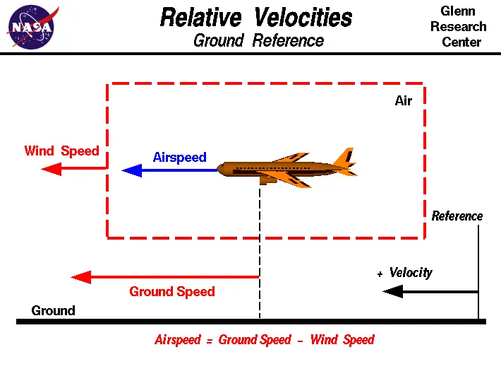
One of the most confusing concepts for young scientists is the relative velocity between objects. aredynamics are generated by an object moving through a fluid (liquid or gas). A fixed object in a static fluid does not generate aerodynamic forces. Hot air balloons "lift" because of buoyancy forces and some aircraft like the Harrier use thrust to "lift" the vehicle, but these are not examples of aerodynamic lift. To genrate lift an object must move through the air, or air must move past the object. Aerodynamic lift depends on the square of the velocity between the object and the air. Now things get confusing because not only can the object be moved through the air, but the air itself can move. To properly define the relative velocity, it is necessary to pick a fixed reference point and measure velocities relative to the fixed point. In this slide, the reference point is fixed to the ground, but it could just as easily be fixed to the aircraft itself. It is important to understand the relationships of wind speed to ground speed and airspeed.
Wind Speed
For a reference point picked on the ground, the air moves relative to the reference point at the wind speed. Notice that the wind speed is a vector quantity and has both a magnitude and a direction. Direction is important. A 20 mph wind from the west is different from a 20 mph wind from the east. The wind has components in all three primary directions (north-south, east-west, and up-down). In this figure, we are considering only velocities along the aircraft's flight path. A positive velocity is defined to be in the direction of the aircraft's motion. We are neglecting cross wind, which occur perpendicular to the flight path but parallel to the ground, and updrafts and downdrafts, which occur perpendicular to the ground.
Ground Speed
For a reference point picked on the ground, the aircraft moves relative to the reference point at the ground speed. Ground speed is also a vector quantity so a comparison of the ground speed to the wind speed must be done according to rules for vector comparissions.
Airspeed
The important quantity in the generation of lift is the relative velocity between the object and the air, which is called the airspeed. Airspeed cannot be directly measured from a ground position, but must be computed from the ground speed and the wind speed. Airspeed is the vector diff between the ground speed and the wind speed.
Airspeed = Ground Speed - Wind Speed
On a perfectly still day, the airspeed is equal to the ground speed. But if the wind is blowing in the same direction that the aircraft is moving, the airspeed will be less than the ground speed.
Examples
Suppose we had an airplane that could take off on a windless day at 100 mph (liftoff airspeed is 100 mph). We are at an airport with an east-west runway that is 1 mile long. The wind is blowing 20 mph towards the west and the airplane takes off going east. The wind is blowing towards the aircraft which we call a headwind. Since we have defined a positive velocity to be in the direction of the aircraft's motion, a headwind is a negative velocity. While the plane is sitting still on the runway, it has a ground speed of 0 and an airspeed of 20 mph:
Airspeed = Ground Speed (0) - Wind Speed (-20) = 20 mph
The airplane starts its take off roll and has a constant acceleration a. From Newton's second law of motoin, the ground speed V at any time t is:
V = a * t
and the distance d down the runway at any time is:
d = 1/2 * a * t^2
For a fixed length runway, this specifies the time to be used in the velocity equation. Let's assume that at 5000 feet down the runway, the velocity is 80 mph. Then the airspeed is given by
Airspeed = Ground Speed (80) - Wind Speed (-20) = 100 mph
and the airplane begins to fly. Now another pilot, with exactly the same airplane decides to take off to the west. The wind is now in the same direction as the motion and this is called a tailwind. The sign on the wind speed is now positive, not negative as with the headwind. The acceleration along the ground is the same, so at 5000 feet down the runway, the ground speed is again 80 mph. The airspeed is then given by:
Airspeed = Ground Speed (80) - Wind Speed (20) = 60 mph
This airplane doesn't have enough airspeed to fly. It runs off the end of the runway!
Unless the aircraft is in a location where it is unwise to taxi under aircraft power and necessitating a tow by a large tractor, the aircraft’s engine(s) is how the craft moves. Obviously, it is prudent to use only the amount of power to get the airplane moving and then reduce the power for taxiing to avoid high volumes of air spreading debris or damaging other aircraft or ground vehicles.
Whether jets or prop airplanes, we use the aircraft’s (engine) power to move on the airfield
4. How an aircraft is pushed to runway when its ready to take off?
Airplanes have engines, and they can use them to move forward along the ground. So they push themselves to the runway.
It true that most of the time, a small vehicle is needed to push the airplane backwards away from the terminal building, because even if a plane can reverse it’s thrust, it’s not always safe to hit the buildings with a jet blast. So the little trucks push the jets back away from the buildings, but after that, the plane can apply a small amount of engine power to roll forward.
They push themselves to the runway.
5).Learn about take off power, tyre design, rolling resistance, tyre pressure, brake forces when landing.
The amount of power that an engine is allowed to produce for a limited period of time for takeoff. The use of takeoff power is usually limited to 5 min for reciprocating engines and up to 2½ min for gas turbine engines. This may not always be the case. Specifically, with respect to reciprocating engines, it is the brake horsepower developed under standard, sea-level conditions and under the maximum conditions of the crankshaft rotational speed and the engine manifold pressure approved for the normal take-off. It is limited in continuous use to the period of time shown in the approved engine specifications. With respect to gas turbine engines, it is the thrust developed under static conditions at a specified altitude and atmospheric conditions of the rotor shaft rotational speed and gas temperature approved for the normal takeoff. It is limited in continuous use to the period of time shown in the approved engine specifications.
Design and Construction of Aircraft tyre
Carcass plies are used to form the tire. They are sometimes called casing plies. An aircraft tyre is constructed for the purpose it serves.
- They support the weight of an aircraft while it is on the ground.
- It also provides the necessary traction for braking and stopping of an aeroplane.
- Tyre also helps to absorb the shock of landing and provide cushioning the roughness of takeoff, roll-out, and taxi operations.
Unlike an automobile or truck tyre, it does not have to carry a load for a long period of continuous operation. However, an aircraft tyre absorbs the high impact loads of landing, and also it’s operating at high speeds for a short time when required.
WHAT IS TIRE ROLLING RESISTANCE?
When you press down on the accelerator in your vehicle, you are essentially transferring energy—in the form of gas or electricity, depending on your automobile, through the engine and other systems in your vehicle. That results in your tires turning and enough momentum being built up to move your automobile. To accomplish this, though, your vehicle must overcome a lot of different factors that can make it resistant to forward movement. One of those factors is the tires’ rolling resistance.
Tire rolling resistance is the energy that your vehicle needs to send to your tires to maintain movement at a consistent speed over a surface. In other words, it is the effort required to keep a tire rolling. The main contributor to rolling resistance is the process known as hysteresis. Hysteresis is essentially the energy loss that occurs as a tire rolls through its footprint. The energy loss must be overcome by the vehicle’s engine, which results in wasted fuel.
Tyres as the only part of the vehicle that is in contact with the ground perform a very important function of carrying the load. Compressed air fills the tyre and carries the overall vehicle weight. Therefore, it is very important to maintain correct tyre pressure.
Tyres are porous and naturally lose air even when they are not being used. Tyres should be neither underinflated nor overinflated but inflated to manufacturers recommended pressure.
In addition to wing spoilers, airplanes use disc brakes. Airplane disc brakes are similar to the braking system in automobiles. They consist of a pair of calipers that, when engaged, squeeze pads against the rotors of an airplane’s landing gear.
landing brakes
Disc brakes are designed to remain static at all times. In other words, they don’t rotate with the wheels of an airplane’s landing gear. As the wheels turn, the disc brakes will remain static and stationary. They are a vital component of an airplane’s braking system because they are designed to apply pressure to the airplane’s wheels. Disc brakes will squeeze the wheels, thereby slowing down the speed at which they spin. In turn, this reduces the speed of the airplane so that it can come to a complete stop on the runway.
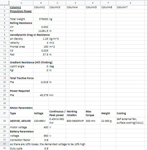
6. A. With necessary assumptions, calculate the force and power required to push / pull an aircraft by a towing vehicle.
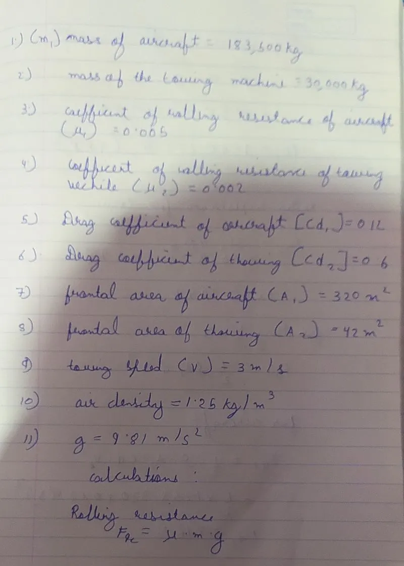
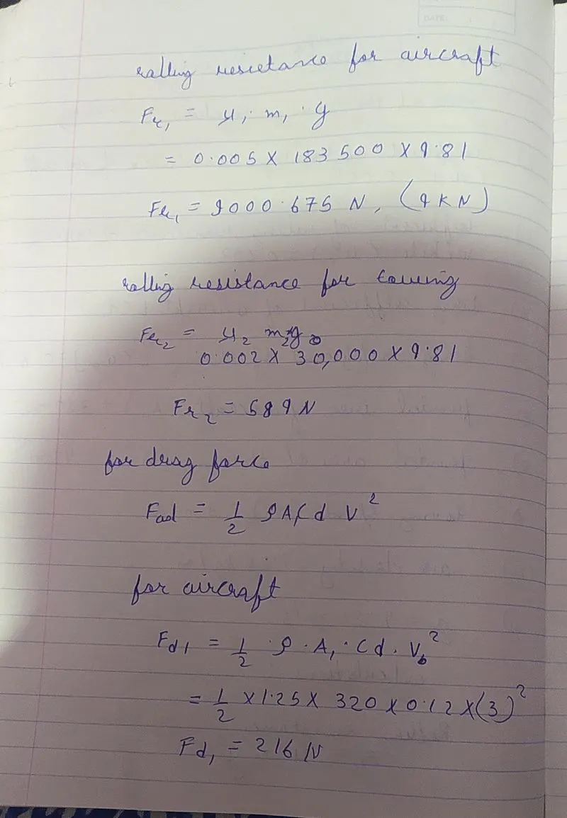
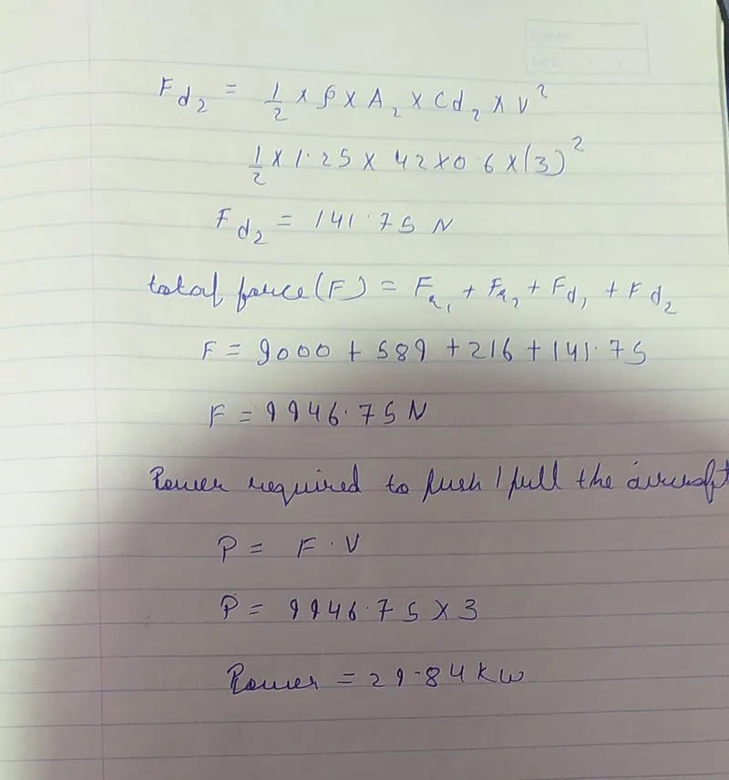
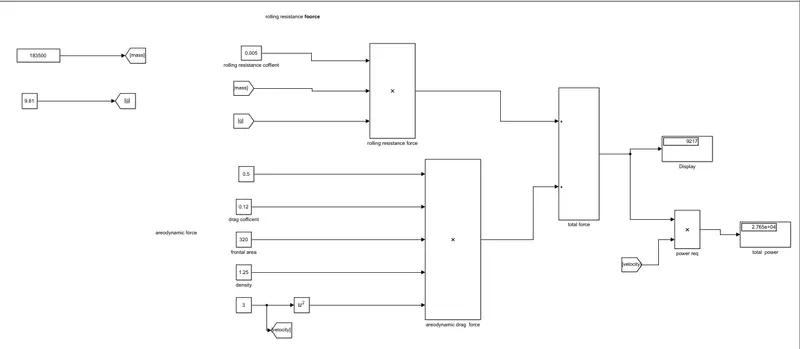
. Develop the model for the calculated force and power using Simulink.
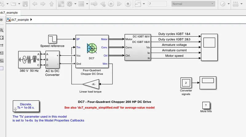
7. A. Design an electric powertrain with type of motor, it’s power rating, and energy requirement to fulfill aircraft towing application in Simulink. Estimate the duty cycle range to control the aircraft speed from zero to highest. Make all required assumptions. Prepare a table of assumed parameters. Draw a block diagram of powertrain.
(Hint :DC7 Block)
Description
The 200 HP DC motor is separately excited with a constant 150 V DC field voltage source. The armature voltage is provided by an IGBT converter controlled by two PI regulators. The converter is fed by a 515 V DC bus obtained by rectification of a 380 V AC 50 Hz voltage source. In order to limit the DC bus voltage during dynamic braking mode, a braking chopper has been added between the diode rectifier and the DC7 block.
The first regulator is a speed regulator, followed by a current regulator. The speed regulator outputs the armature current reference (in p.u.) used by the current controller in order to obtain the electromagnetic torque needed to reach the desired speed. The speed reference change rate follows acceleration and deceleration ramps in order to avoid sudden reference changes that could cause armature over-current and destabilize the system. The current regulator controls the armature current by computing the appropriate duty ratios of the 5 kHz pulses of the four IGBT devices (Pulse Width Modulation). For proper system behaviour, the instantaneous pulse values of IGBT devices 1 and 4 are opposite to those of IGBT devices 2 and 3. This generates the average armature voltage needed to obtain the desired armature current. In order to limit the amplitude of the current oscillations, a smoothing inductance is placed in series with the armature circuit.
output:-
Simulation
Before starting the simulation, set the initial bus voltage to 515 V via the GUI block ('Initial States Setting' button and 'Cbus' variable).
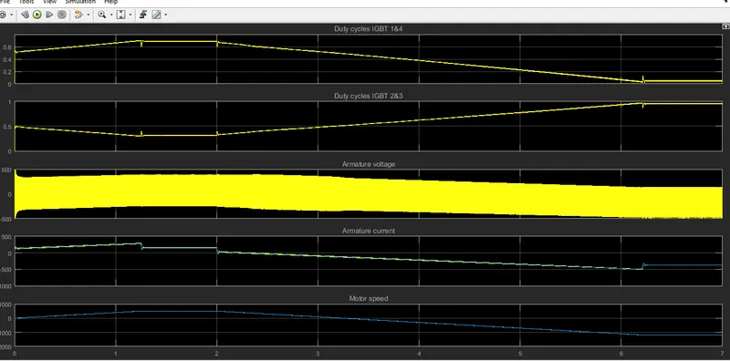
Start the simulation. You can observe the motor armature voltage and current, the four IGBT pulses and the motor speed on the scope. The current and speed references are also shown.
The motor is coupled to a linear load, which means that the mechanical torque of the load is proportional to the speed.
The speed reference is set at 500 rpm at t = 0 s. Observe that the motor speed follows the reference ramp accurately (+400 rpm/s) and reaches steady state around t = 1.3 s.
The armature current follows the current reference very well, with fast response time and small ripples. Notice that the current ripple frequency is 5 kHz.
At t = 2 s, speed reference drops to -1184 rpm. The current reference decreases to reduce the electromagnetic torque and causes the motor to decelerate with the help of the load torque.
At t = 2.2 s, the current reverses in order to produce a braking electromagnetic torque (dynamic braking mode). This causes the DC bus voltage to increase.
At t = 3.25 s, the motor reaches 0 rpm and the load torque reverses and becomes negative. The negative current now produces an accelerating electromagnetic torque to allow the motor to follow the negative speed ramp (-400 rpm/s). At t = 6.3 s, the speed reaches -1184 rpm and stabilizes around its reference.
B. Also, Design the parameters in excel sheet.