FINAL INDEPENDENT PROJECT
Aim: To plot curve of turning moment diagram.
To find the maximum torque.
THEORY:
Turning moment:The turning effect of a force is known as the moment. It is the product of the force multiplied by the perpendicular distance from the line of action of the force to the pivot or point where the object will turn.
Turning moment diagram:The turning moment diagram also known as crank effort diagram , The turning moment diagram is the graphical representation of the turning moment or crank effort for various positions of crank . It is plotted on Cartesian coordinates ,in which the turning moment is taken as the ordinate and crank .
Interia force:an imaginary force suppossed to act upon an accelerated body, equal in magnitude and in direction opposite to the resultant of the real forces.
Piston force:Piston effort is defined as the net or effective force applied on the piston along the line of stroke .
Thrust force:Thrust is a force or a push. When a system pushes or accelerates mass in one direction, there is a thrust (force) just as large in the opposite direction.
Explaination:
crank pin circle radius of a horizontal engine in m
r = 0.3;
mass of reciprocating parts in kg
m = 250;
net load on the piston in N
fl = 68730;
connecting rod length between centers in m
l = 0.6;
engine rpm
N = 250;
inputs are provided to find other parameters.
s the ratio of connecting rod length to crank pin circle radius
n = 0.6/r
omega = ((2*pi*N)/60) after definnig the inputs
for loop is used for defining theta
fi = 250*omega^2*r*((cos(theta))+((cos(2*theta))/n))
to find the interia force.
from that we got piston force
fp = fl-fi
phi = asin((sin(theta))/n) finding phi to put on to get thrust force
fq = fp/cos(phi)
by getting thrust force we can geyt the tangentical force
ft = fq*sin(theta+phi)
from that we can ditermine the torque
t = ft*r
after that we can use plot command to plot the turning moment diagram.
clear all
close all
clc

%inputs
%crank pin circle radius of a horizontal engine in m
r = 0.3;
%mass of reciprocating parts in kg
m = 250;
%net load on the piston in N
fl = 68730;
%connecting rod length between centers in m
l = 0.6;
%engine rpm
N = 250;

%is the ratio of connecting rod length to crank pin circle radius
n = 0.6/r;

omega = ((2*pi*N)/60);

%for loop for defining theta
 for d = 1:360
    theta = ((pi*d)/180);
    %interia force
    fi = 250*omega^2*r*((cos(theta))+((cos(2*theta))/n));

    %piston effort
    fp = fl-fi;

    phi = asin((sin(theta))/n);

    %thrust force
    fq = fp/cos(phi);

     %tangential force
     ft = fq*sin(theta+phi)

     % torque
     t = ft*r;
     torque(:,d) = t;
 end

     %ploitting
 plot(1:360,torque)
 xlabel('crank angle in degree')
 ylabel('torque in N-m')
 title('turning moment diagram')
 grid on
 disp('the max torque in N-m is')
 disp(max(torque));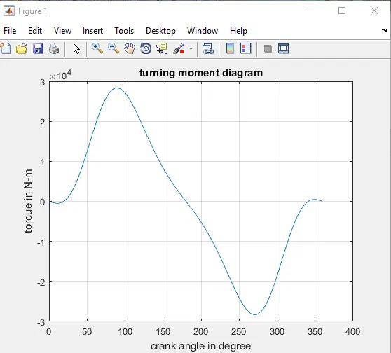
Results:The curve is exicuted well and got the value of maximum torque.