Project-1: Powertrain for aircraft in runways
- Manufacturer's empty weight (MEW)
Also called Manufacturer's Weight Empty (MWE)or Licensed Empty Weight
It is the weight of the aircraft "as built" and includes the weight of the structure, power plant, furnishings, installations, systems and other equipment that are considered an integral part of an aircraft.
This excludes any baggage, passengers, or usable fuel.
Zero-fuel weight (ZFW)
This is the total weight of the airplane and all its contents (including unusable fuel), but excluding the total weight of the usable fuel on board.
As a flight progresses and fuel is consumed, the total weight of the airplane reduces, but the ZFW remains constant.
Maximum zero fuel weight (MZFW) is the maximum weight allowed before usable fuel and other specified usable agents (engine injection fluid, and other consumable propulsion agents) are loaded.
Operating empty weight (OEW) (Roughly equivalent to basic empty weight on light aircraft)
It is the basic weight of an aircraft including the crew, all fluids necessary for operation such as engine oil, engine coolant, water, unusable fuel and all operator items and equipment required for flight but excluding usable fuel and the payload.
Payload
It is the carrying capacity of an aircraft. It includes cargo, people, extra fuel. In the case of a commercial airliner, it may refer only to revenue-generating cargo or paying passengers.
Maximum takeoff weight (MTOW)
This is the maximum weight at which the pilot of the aircraft is allowed to attempt to take off3.
Regulated takeoff weight (RTOW)
Depending on different factors (e.g. flap setting, altitude, air temperature, length of runway), RTOW or maximum permissible takeoff weight varies for each takeoff. It can never be higher than MTOW.
Maximum landing weight (MLW)
This is the maximum weight at which an aircraft is permitted to land.
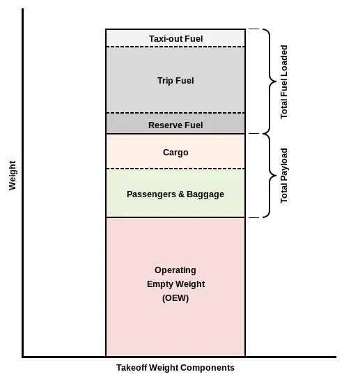
The following image depicts takeoff weight components.
Maximum ramp weight (MRW)
also called maximum taxi weight (MTW)
It is the maximum weight authorized for maneuvering (taxiing or towing) an aircraft on the ground.
Aircraft gross weight
It is the total aircraft weight at any moment during the flight or ground operation. This decreases during flight due to fuel and oil consumption.
- DIFFERENCE BETWEEN GROUND AND AIR SPEED:
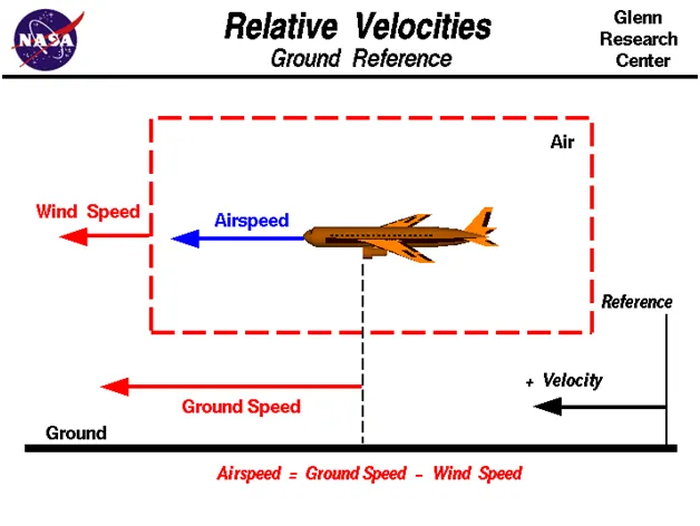
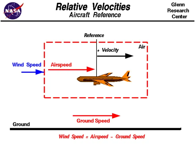
True airspeed is simply the speed at which an aircraft is moving relative to the air it is flying in. As such, it’s also the speed at which the air is flowing around the aircraft’s wings.
Ground speed, on the other hand, is the aircraft’s speed relative to the ground. One thing that should be noted here is that it’s its horizontal rather than vertical speed – an aircraft climbing completely vertically would have a ground speed of zero.
In other words, while airspeed is what determines whether there is enough airflow around an aircraft to make it fly, ground speed is what determines how fast an aircraft will get to its destination.
While ground speed is the airplane’s speed relative to the surface of the Earth, airspeed – at least true airspeed – is its speed relative to the air it is flying in.
3.
The ‘traditional’ method of letting the ground vehicle to move the aircraft is to be attached to the aircraft nose landing gear by means of a towbar. The same towbar attachment and the ground vehicle can also be used for Aircraft Towing in the forward direction.
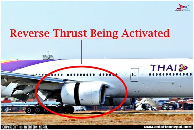
Thrust Reversal, known in the majority as reverse thrust, is projected in the opposite way and is used after landing, in the case of rejected departures or, in some cases, in flight, to decelerate the aircraft. Pushback is used by aircraft to move backward on the ground using the power of their engines along with the reverse thrust of the aircraft.
Some of the effects of using Engine power in the ground:
- Need to maintain the fuel
- Has more wear and tear
- More maintenance cost
- No back view
- Injury to ground staff
- Damage to engine and aircraft
- Damage to the terminal at the airport.
- PUSHBACK OF THE FLIGHT:
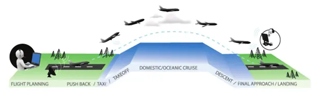
Taxiing refers to the movement of an aircraft on the ground, under its own power. The aircraft moves on wheels. An airplane uses taxiways to taxi from one place on an airport to another; for example, when moving from a terminal to the runway.
The aircrafts always moves on the ground following the yellow lines, to avoid any collision with the surrounding buildings, vehicles or other aircrafts. The taxiing motion has a speed limit. Before making a turn, the pilot reduces the speed further to prevent tire skids. Just like cars, there is a certain list of priorities during taxiing. The aircrafts that are landing or taking off have higher priority. The other aircrafts have to wait for these aircrafts before they start or continue taxiing.
The thrust to propel the aircraft forward comes from its propellers or jet engines. Steering is achieved by turning a nose wheel or tail wheel/rudder; the pilot controlling the direction travelled with their feet. The use of engine thrust near terminals is restricted due to the possibility of jet blast damage. This is why the aircrafts are pushed back from the buildings by a vehicle before they can start their own engines for taxiing.
Take-Off
Takeoff is the phase of flight in which an aircraft goes through a transition from moving along the ground (taxiing) to flying in the air, usually starting on a runway. Usually the engines are run at full power during takeoff. Following the taxi motion, the aircraft stops at the starting line of the runway. Before takeoff, the engines, particularly piston engines, are routinely run up at high power to check for engine-related problems. This makes a considerable noise. When the pilot releases the brakes, the aircraft starts accelerating rapidly until the necessary speed for take-off is achieved.
The takeoff speed required varies with air density, aircraft weight, and aircraft configuration (flap and/or slat position, as applicable). Air density is affected by factors such as field elevation and air temperature.
Descent
A descent during air travel is any portion where an aircraft decreases altitude. Descents are an essential component of an approach to landing. Other partial descents might be to avoid traffic, poor flight conditions (turbulence or bad weather), clouds (particularly under visual flight rules), to see something lower, to enter warmer air (in the case of extreme cold), or to take advantage of wind direction of a different altitude. Normal descents take place at a constant airspeed and constant angle of descent (3 degree final approach at most airports). The pilot controls the angle of descent by varying engine power and pitch angle (lowering the nose) to keep the airspeed constant.
At the beginning of and during the descent phase, the engine noise diminishes further as the engines are operated at low power settings. However, towards the end of the descent phase, the passenger can feel further accelerations and an increase in the noise. This is to realize the “final approach” before taking “landing position”.
Landing
Landing is the last part of a flight, where the aircraft returns to the ground. Aircraft usually land at an airport on a firm runway, generally constructed of asphalt concrete, concrete, gravel or grass. To land, the airspeed and the rate of descent are reduced to where the object descends at a slow enough rate to allow for a gentle touch down. Landing is accomplished by slowing down and descending to the runway. This speed reduction is accomplished by reducing thrust and/or inducing a greater amount of drag using flaps, landing gear or speed brakes. As the plane approaches the ground, the pilot will execute a flare (roundout) to induce a gentle landing. Although the pilots are trained to perform the landing operation, there are “Instrument Landing Systems” in most of the airports to help pilots land the aircrafts. An instrument landing system (ILS) is a ground-based instrument approach system that provides precision guidance to an aircraft approaching and landing on a runway, using a combination of radio signals and, in many cases, high-intensity lighting arrays to enable a safe landing during instrument meteorological conditions (IMC), such as low ceilings or reduced visibility due to fog, rain, or blowing snow.
At the beginning of the landing phase, the passengers will hear the opening of the doors of the landing gears. As the landing gears are deployed, they will create an additional drag and an additional noise. Immediately after touch-down, the passengers can hear a blowing sound, sometimes with increasing engine sound. This is the engine’s thrust reverses, helping the aircraft to slow down to taxi speeds by redirecting the airflow of the engines for- ward. Once the aircraft is decelerated to low speed, it can taxi to the terminal building.
- Takeoff power:
On take-off, in order to position the aircraft to a safe height away from terrain and obstacles (i.e. a flight path of maximum height and minimum ground distance desired), the engine thrust is set to a high ‘take-off power’ setting (although this is not necessarily full power) and the aircraft attitude is pitched up to maintain a specific speed (usually in the region of V2 + 15kts). Once the ‘safe height’ is reached the engine thrust can therefore be reduced to a more appropriate (i.e. efficient) setting and the aircraft flight path can be changed to a more appropriate (i.e. efficient) flight path
Power = Mass x Acceleration x distance/time
To many it means "how much throttle" , which is how much fuel/time.
"Throttle" x prop efficiency = Thrust.
This gives a unit of Force that can be directly compared to glide data as follows:
Potential energy Mass x Gravity x altitude loss = Thrust x horizontal distance flown
This rearranged to Thrust = Mass x Gravity x altitude loss/horizontal distance flown
Thrust = force required for straight and level flight, expressed in "pounds or Newtons"
So if your plane weighs 10 lb and glides 5:1, you need 2 lb of thrust for straight and level flight.
One would at least double, or even triple this for "takeoff power", depending on your performance preferences. Sufficient "takeoff power" will give a safe climb rate to avoid difficulties with downdrafts.
TIRE DESIGN:
When it comes to safety, tires are one of the most important components of aircraft. They help to absorb the shock of landing and provide cushioning. It also provides the necessary traction for braking and stopping of an aircraft.
An aircraft tire is designed to withstand extremely heavy loads while landing, take off, taxing, and parking. The number of wheels required for aircraft increases with the weight of the aircraft, as the weight of the airplane needs to be distributed more evenly.
DESIGN AND CONSTRUCTION:
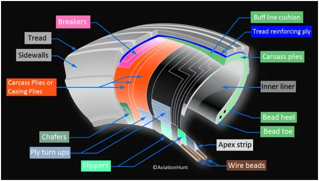
Carcass plies are used to form the tire. They are sometimes called casing plies. An aircraft tire is constructed for the purpose it serves.
- They support the weight of an aircraft while it is on the ground.
- It also provides the necessary traction for braking and stopping of an airplane.
- Tire also helps to absorb the shock of landing and provide cushioning the roughness of takeoff, roll-out, and taxi operations.
Unlike an automobile or truck tire, it does not have to carry a load for a long period of continuous operation. However, an aircraft tire absorbs the high impact loads of landing, and also it’s operating at high speeds for a short time when required.
Retreading – Retreading is methods of restoring a worn tire by renewing the tread area or by renewing the tread area plus one or both sidewalls. Repairs are included in the tire retreading process.
Load Rating – Load rating is the maximum permissible load at a specified inflation pressure.
Ply Rating – Ply Rating is used to identify the maximum recommended load rating and inflation pressure for a specified tire. It is an index of tire strength.
Speed Rating – The speed rating is the maximum takeoff speed to which the tire has been tested.
Skid Depth – Skid depth is the distance between the tread surface and the deepest groove as measured in the mould.
Aircraft tires must have an approved speed and load rating and have sufficient clearance when retracted through landing gear to allow for tire growth. Tire growth is the increase in the size of the tire due to centrifugal forces at high speed.
ROLLING RESISTANCE:
The friction between the aircraft and the runway will be proportional to the normal force exerted by the aircraft on the runway.
F = m(W-L).
The normal force will be the difference between the weight of the aircraft and the lift, the friction coefficient will be typical of a magnitude of 0.02 for a standard runway.
Tyre pressure:
Aircraft tires generally operate at high pressures, up to 200 psi (14 bar; 1,400 kPa) for airliners, and even higher for business jets. The main landing gear on the Concorde was typically inflated to 232 psi (16.0 bar), whilst its tail bumper gear tires were as high as 294 psi.
Aircraft tires are usually inflated with nitrogen to minimize expansion and contraction from extreme changes in ambient temperature and pressure experienced during flight. Dry nitrogen expands at the same rate as other dry atmospheric gases (normal air is about 80% nitrogen), but common compressed air sources may contain moisture, which increases the expansion rate with temperature.
The requirement that an inert gas, such as nitrogen, be used instead of air for inflation of tires on certain transport category airplanes was prompted by at least three cases in which the oxygen in air-filled tires had combined with volatile gases given off by a severely overheated tire and exploded upon reaching auto ignition temperature. The use of an inert gas for tire inflation eliminates the possibility of tire explosion.
Brakes Forces when Landing:
An electrical signal is sent from the flight deck to hydraulic actuators near the main landing gear. Here, hydraulic fluid at 3,000 pound per square inch is used to force the brake unit against the wheel, thus slowing it down.
Braking an aircraft is a challenging job for most of the pilots especially during the landing in a rainy and cross wind environment.
In order to encounter this kind of problem pilots usually make use of spoilers and reverse thrust method in order to have a safe landing so that the energy required to apply brakes on tires can be reduces and henceforth do not skid.
A typical commercial landing speed will range between 150 to 165MPH and for the passenger flight it is about 166 to 172mph.
6 . A .
Assumptions made:
Total mass of the aircraft = 575000 kgs.
Mass of the push back = 1000kgs
Rolling Resistance:
Coefficient of rolling resistance (Crr) = 0.002
Rolling resistance force is given by Frr = Crr.m.g
Frr = 0.002*575000*9.8
Frr = 11281.5N
For the towing Vehicle, Frrt = 0.002*1000*9.81
Frr = 19.62N.
As the towing vehicle resistance is so less compared to the Aircraft because this is a heavy aircraft these can be neglected.
AERODYNAMIC RESISTANCE:
Drag coefficient = 0.025
Air Density r= 1.125 kg/m^3
Frontal Area (A) = 150 m^2
Velocity (v)= 14.5 kmph
Far = ½. Cd. r.A.v
Far = 0.5*0.025*1.125*150.4^2
Far = 33.75N
As the vehicle and plane is moving at very low speed Aerodynamic resistance can be neglected.
HILL CLIMB RESISTANCE:
Runways are constructed flat so gradient resistance/ hill climb force is neglected.
TOTAL RESISTANCE:
Ft = 11.2815kN
POWER REQUIRED:
P = Ft.*v = 11.2815 * 4 = 45.26kW.
The main power required by the tow vehicle is 45.26kW to taxi a heavy aircraft at 4 m/s.
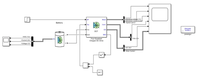
6.B. SIMULINK MODEL
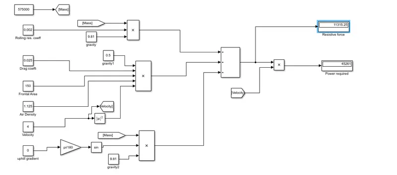
7. A.Estimation of Duy Cycle :
Based on the calculation done in study 6, the power required for towing the aircraft is 45.26KW.
Motor considered for the drive train is REB 90.
Considering 60KW as continous power, the voltage will be 400V.
Battery power is considered to be 550V.
Duty cycle is given by Vo/Vb = 400/550 = 0.7272
As there will be losses due to the resistance of FET and Inductance,
Correction factor is considered to be 90%.
As there is 10% loss, the voltage demanded by the motor should be 10% more .
d = 0.799 = 0.8
So the voltage demand should be around 440V from the battery.
|
Assumed Parameters: |
|
|
Mass of the aircraft |
575000kg |
|
Co.eff of push back truck |
1000 kg |
|
Rolling resitance coeff |
0.002 |
|
Drag coefficient |
0.025 |
|
Air Desnity |
1.125 kg/m^3 |
|
Frontal area |
150 m^2 |
|
Velocity |
4 m/s |
|
Uphill gradient |
0 deg |
|
Battery voltage |
550V |
|
Correction factor |
0.8 |
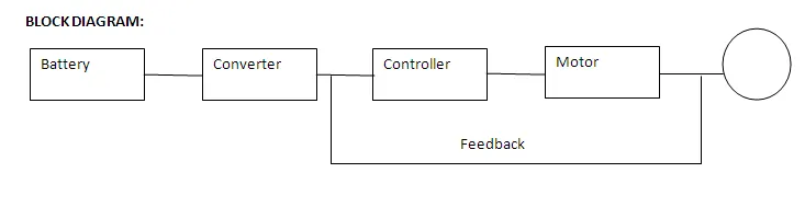
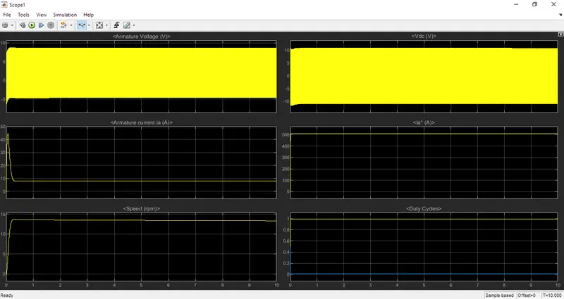
SIMULINK MODEL:
7.b. Excel sheet is attached as the attachment. Kindly find the attachment.