Project-1: Powertrain for aircraft in runways
Part A :
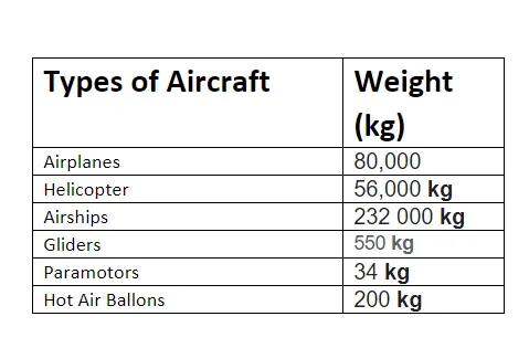
Q-1) List out the total weight of various types of aircraft.
An aircraft is a vehicle that is able to fly by gaining support from the air. It counters the force of gravity by using either static lift or by using the dynamic lift of an airfoil or in a few cases the downward thrust from jet engines. Common examples of aircraft include airplanes, helicopters, airships (including blimps), gliders, paramotors, and hot air balloons
Q-2 ) Is there any difference between ground speed and airspeed?
Ground speed is the horizontal speed of an aircraft relative to the Earth’s surface. An aircraft diving vertically would have a ground speed of zero.
Ground speed can be determined by the vector sum of the aircraft's true airspeed and the current wind speed and direction; a headwind subtracts from the ground speed, while a tailwind adds to it. Winds at other angles to the heading will have components of either headwind or tailwind as well as a crosswind component.
Airspeed indicates the aircraft's speed relative to the air mass. The air mass may be moving over the ground due to wind, and therefore some additional means to provide position over the ground is required. Ground speed radar can measure it directly.
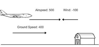
Ground speed is quite different from airspeed. When an aircraft is airborne the ground speed does not determine when the aircraft will stall, and it doesn't influence the aircraft performance such as rate of climb.
Q-3) Why is it not recommended to use aircraft engine power to move it on the ground at the Airport?
Taxiing refers to an aircraft’s movement while on the ground, under its own power. This term excludes the accelerating run along a runway before takeoff and the decelerating run immediately upon landing.
Aircraft does not use its engine power to move it on the ground at Airport because of the following reasons:
- Propulsion -
The thrust to propel the aircraft forward comes from its propellers or jet engines. Reverse thrust for backing up can be generated by thrust reversers or reversible pitch propellers, a procedure is known as a power back. Most aircraft, however, are not designed to back up on their own and must be pushed back either by hand or by using an aircraft tug. - Control - Steering is achieved by turning a nose wheel or tail wheel/rudder, the pilot controls the direction traveled with their feet. Larger jet aircraft have a tiller wheel on the left side of the cockpit that acts as a steering wheel allowing the nosewheel to be turned hydraulically. Braking is controlled by differential toe or heel brakes. Not all aircraft have steerable wheels, and in some cases, steering is solely by means of differential braking or solely by means of the rudder
- Safety - When taxiing, aircraft travel slowly. This ensures that they can be stopped quickly and do not risk wheel damage on larger aircraft if they accidentally turn off the paved surface. Taxi speeds are typically 30 to 35 km/h.
- Hover Taxi - Skid-equipped helicopters and other VTOL (Vertical Take-Off and Landing) aircraft conduct hover taxiing to move in ground effect in the same manner that wheel-equipped aircraft ground taxi.
Q-4) How an aircraft is pushed to the runway when it is ready to take off?
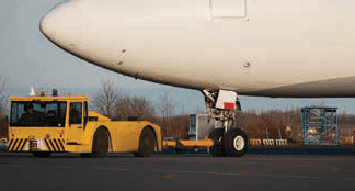 |
| Figure 1. Example of a tow tractor |
 |
| Figure 2. Example of a tow bar |
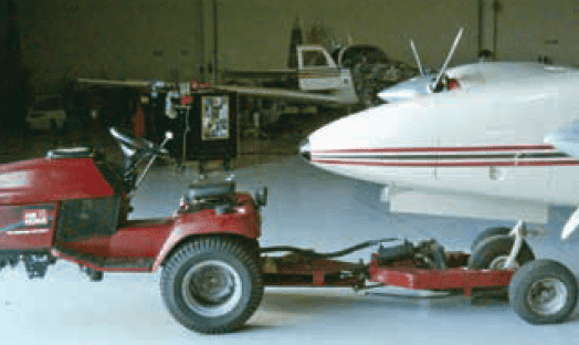 |
| Figure 3. The typical smaller aircraft tow tractor |
Q-5) what about take-off power, tyre design, rolling resistance, tyre pressure, brake forces when landing?
- Take Off Power -
Takeoff is the phase of flight in which an aerospace vehicle leaves the ground and becomes airborne. For aircraft traveling vertically, this is known as liftoff.
For aircraft that take off horizontally, this usually involves starting with a transition from moving along the ground on a runway. For balloons, helicopters, and some specialized fixed-wing aircraft (VTOL aircraft such as the Harrier), no runway is needed. - Tyre Design -
When it comes to safety, tyres are one of the most important components of aircraft. They help to absorb the shock of landing and provide cushioning. It also provides the necessary traction for the braking and stopping of an aircraft.

An aircraft tyre is designed to withstand extremely heavy loads while landing, take off, taxing, and parking. The number of wheels required for aircraft increases with the weight of the aircraft, as the weight of the aeroplane needs to be distributed more evenly. - Tyre Pressure -
Depending on the weight of the plane and the number of tires the cold pressure is between 200 and 300+ psi. These tyres are made of rubble like a car tire but intensively designed to stay flexible at very low temperatures at high altitudes, these are basically radial-type tires but without steel belts instead, Kevlar is used as they do not have to withstand road hazards like car tire does.
- Brake Force in Landing -
The maximum brake force depends on the frictional force between the wheel and the track as these braking devices are incorporated in the landing gears. If braking induces a greater moment on the wheel than the frictional force, the wheel stops rolling and starts to skid on the track surface similarly if a moment induces is lesser than the frictional force then slips start. So braking must be applied accordingly.
Aircraft braking systems include:
- Aircraft disc brakes in the landing gear are used to break the wheels while touching the ground. These brakes are operated hydraulically or pneumatically. In most modern aircraft they are activated by the top section of the rudder pedals i.etoe brakes. In some older aircraft, the bottom section is used instead of heel brakes. Levers are used in a few aircraft. Most aircraft are capable of differential braking.
- Thrust reversers, allow thrust from the engines to be used to slow the aircraft.
- Air brakes, dedicated flight control surfaces that work by increasing drag
- Rolling resistance -
Tire rolling resistance is defined as the force required to maintain the forward movement of a loaded pneumatic tire in a straight line at a constant speed. And just like the laws of physics and forces of nature, it is an obstacle every vehicle has to overcome to transport passengers and cargo to their destinations.
Tire rolling resistance is caused by the natural viscoelastic properties of rubber along with the tire's internal components constantly bending, stretching, and recovering as they cycle between their loaded (where the tread footprint flattens against the road) and unloaded states. The final contributor to tire rolling resistance is the tread's interaction with the road.
Part B :
Q-6) A. With necessary assumptions, calculate the force and power required to push/pull an aircraft by a towing vehicle
- when an Aircraft move on the ground, generally five forces act on it:
- Friction force(Frr)
- Hill Climb force(Fhc)
- Force due to gravity(Fg)
- Drag force(Faero)
- Traction force(Fx)
In order to pull an aircraft, these forces must be countered by Towing Vehicle and let aircraft move with constant speed so acceleration is zero so Traction force(Fx) is also zero.
**Here I have used Free Body Diagram of Car just to show the of the direction of forces.
- Friction force(Frr) - it is the resistance force exiting btw aircraft tyre and runway,
Frr = μ * N,
where,
μ : coefficient of friction between surface and tyres
N : Normal force i.e perpendicular component of force on moving surface,
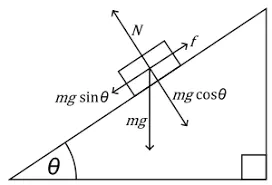
N = mg cosθ, where m is the mass of the airplane
Frr = μ * mg cosθ
- Hill Climb force(Fhc) - Force required to climb hill
Fhc = mg sinθ
- Gravitational force(Fg) - Force due to gravity(g)
Fg = mg
- Drag Force(Faero) - is the force offered by surrounding air on the vehicle when it moves
F aero = 0.5 * Cd * ρ * A * V^2
where, ρ - density of surrounding Air
A - frontal area of Airplane
V - velocity of the vehicle
Cd - coefficient of Drag
Total Force(Ft) = Friction force(Frr) + Hill Climb force(Fhc) + Force due to gravity(Fg) + Drag force(Faero)
This Total force must be applied by towing vehicle to drive Airplane.
Now Power required by towing vehicle to tow(Ptow) = Total Force(Ft) * Vehicle velocity(v)
The above calculation is based on several assumptions:
- The vehicle moves with a constant speed
- value of coefficients used remains constant
- the density of surrounding Air remains constant
B. Develop the model for the calculated force and power using Simulink.
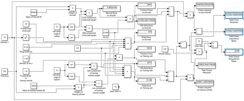
Q-7). A. Design an electric powertrain with the type of motor, its power rating, and energy required to fulfill aircraft towing application in Simulink.
Estimate the duty cycle range to control the aircraft speed from zero to highest.
Make all required assumptions.
- In order to Design an Electric Powertrain for Towing vehicles. we need to calculate the total Power requirement of Towing vehicle,
Total power required by towing vehicle(Ptotal) = Power required to towing(Ptow) + Power required by Towing vehicle itself(Pv)
We know,
- Friction force(Frr) - it is the resistance force exiting btw aircraft tyre and runway,
Frr = μ * N,
N = Mt * g cosθ, where m is the mass of Towing Vehicle
Frr = μ * Mt *g cosθ
- Hill Climb force(Fhc) - Force required to climb hill
Fhc = Mt *g sinθ
- Gravitational force(Fg) - Force due to gravity(g)
Fg = Mt *g
- Drag Force(Faero) - is the force offered by surrounding air on the vehicle when it moves
Faero - 0.5 * Cd * ρ * At * V^2
where, Cd - coefficient of Drag
ρ - density of surrounding Air
A - frontal area of Towing vehicle
V - velocity of the vehicle
Total Force(Ftv) = Friction force(Frr) + Hill Climb force(Fhc) + Force due to gravity(Fg) + Drag force(Faero)
Power required for towing vehicle itself(Pv)= Total Force(Ftv) * Vehicle velocity(v)
Total Torque required = Total Force * wheel radius(r) / Gear ratio(g)
Total power required(Ptotal) = Ptow + Pv
Total Energy required (Etotal) = Ptotal * time
lets,
Total Mass of airplane m = 50000 kg
Total Mass of towing vehicle Mt = 3000 kg
Gravity g = 9.8
cimbing angle θ = 5°
friction coefficient μ = 0.005
Coefficeint of Drag Cd = 0.19
Density of surrounding Air ρ = 1.25 kg/m^3
Frontal area of Airplane A = 40 m^2
Frontal area of towing vehicle At = 1.8 m^2
Velocity of vehicle V = 10 m/s
wheel radius r = 0.6 m
gear ratio G = 12
Total Force required = 47.56 KN
Torque required = 28.534 kNm
Power required for towing(Ptow) = 448.706 Kw
Power required by Towing vehicle itself(Pv) =26.851 Kw
The torque required by motor = 2.3778 kNm
Total power required = 475.557 Kw
Design an Electric Powertrain for Towing vehicle -
The design of an Electric powertrain is to deliver the required energy in a given time i.e selection of particular motor to give required power output for a given input, which involves power converters to match the required voltage and current in order to meet speed and torque respectively.
Assuming the operational time of the towing vehicle is around 10 min for 1 cycle,
Energy required(Kwh) = Total power required(kw) * Cycle time(hour)
= 475.557 * (10/60)
= 79.26 Kwh
Now we have to choose a Motor to provide a torque of 2.548 kNm torque and a Battery to store minimum energy of 85 kwh.
Motor Selection -
Here we select a Brushless DC Motor which has a power rating of around 510 kw and should be able to deliver 2.55 KNm torque instantaneously at a given second.
In order to control the speed of motor, we use a Controller , which regulates the voltage to the Rated voltage at that speed, for this voltage regulation we use the concept of Power Electronics Switching.
Here the control is achieved not on the magnitude axis but on the Time axis i.e we get control over the voltage applied to the motor by Switching Action. Power electronics is a subject where control is achieved by switching.
A duty cycle is the fraction of one period in which a signal or system is active. The duty cycle is commonly expressed as a percentage or a ratio. A period is a time it takes for a signal to complete an on-and-off cycle.
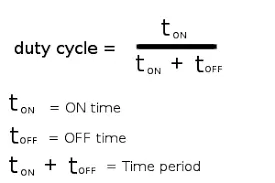
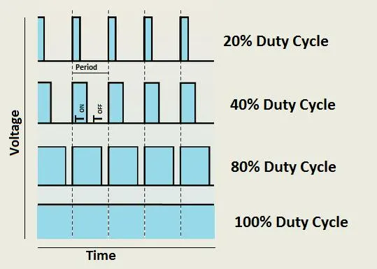
For our towing vehicle total power required is 509.74 Kw and with overall efficiency 0.93 the input power will be 548 Kw and let assume starting Power is 70 Kw therefore
Duty cycle at start = 70 / 509.7
= 13.7 %
Duty cycle at maxmimum power = 509.74 / 548
= 93 %
∴ Duty cycle ∈ [ 0.137 0.93 ]
The Electric Vehicle Reference application is configured with a mapped motor and battery. This diagram shows the powertrain configuration.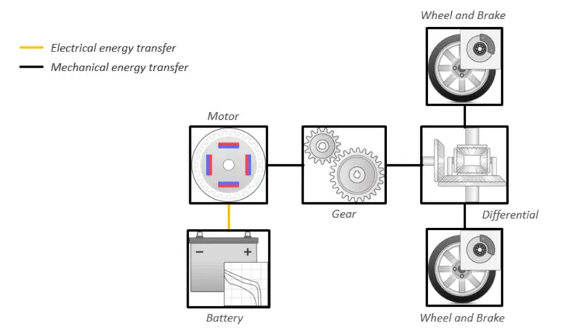
This powertrain configuration represents a full electric vehicle model with a motor-generator, battery, direct-drive transmission, and associated powertrain control algorithms
- Battery: An electric vehicle battery (EVB) is used to power the electric motors of an electric vehicle or hybrid electric vehicle (HEV). These batteries are usually rechargeable batteries and are typically lithium-ion batteries, which are specifically designed for a high ampere-hour (or kilowatt-hour) capacity.
Electric-vehicle batteries differ from starting, lighting, and ignition batteries as they are designed to give power over sustained periods of time and are deep-cycle batteries. Batteries for electric vehicles are characterized by their relatively high power-to-weight ratio, specific energy, and energy density; smaller, lighter batteries are desirable because they reduce the weight of the vehicle and therefore improve its performance.
- Motor-Generator: Moter is Configured with electric battery wear Generator is Mapped motor with implicit controller i.e
In an electric car, there is no alternator, the motor in an electric car acts as both the motor and an alternator. when we foot is on the accelerator the battery starts the motor, which supplies energy to the gears, which rotates the tires. - the rotor gets pulled along by the rotating magnetic field, requiring more torque. But when you let off of the accelerator i.e our foot comes off the accelerator, the rotating magnetic field stops, and the rotor starts spinning faster (as opposed to being pulled along by the magnetic field). When the rotor spins faster than the rotating magnetic field in the stator, this action recharges the battery, acting as an alternator. -
Controllers :
Its main function is to determine the motor torque and brake pressure commands, Specifically, the controller subsystem includes a powertrain control module (PCM)
with:
-
Regenerative braking control
-
Motor torque arbitration and power management
-
Converts the driver accelerator pedal signal to a torque request.
-
Converts the driver brake pedal signal to a brake pressure request. The algorithm multiplies the brake pedal signal by a maximum brake pressure.
-
Implements a regenerative braking algorithm for the traction motor to recover the maximum amount of kinetic energy from the vehicle.
-
Implements a virtual battery management system. The algorithm outputs the dynamic discharge and charge power limits as functions of battery state of charge (SOC).
-
Implements a power management algorithm that ensures the battery dynamic discharge and charge power limits are not exceeded.
-
-
- Transmission System : A transmission system for an electric vehicle includes a gearbox that produces a different rotation ratio between a drive motor and drives wheels during the running of the electric vehicle, a differential that serves to absorb the power of the gearbox to overcome the rotation speed difference between the drive wheels, and two-wheel axles which are used to deliver the power to the drive wheels from the differential, the gearbox has a housing which is connected to a vehicle frame of the electric vehicle via a universal coupling. When the electric vehicle runs on a bumpy road and makes a turn, the vehicle frame is able to swing up and down and pivot left and right with respect to the gearbox housing, so as to reduce the bounce of the vehicle and dampen the centrifugal force caused tilt or roll of the vehicle, thus improving driving comfort and stability
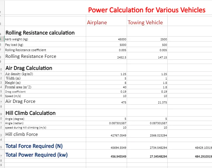
B. Also, Design the parameters in an excel sheet
Reference :
- https://www.google.com/
- https://www.tirerack.com/