Week -2
AIM:
- Make a Simulink model of Doorbell as shown below using solenoid block.
2. Use a thermistor to sense the temperature of a heater & turn on or turn off the fan as per below conditions:
CONDITIONS:
- 1) Temperature source: In the above arrangement of Doorbell, create a situation where the switch is closed for 2 seconds and then released. Observe the physical movement of the plunger.
- 2)Fan conditions: ON if the temperature above 25 °C, OFF otherwise.
EXPLANATION:
- Simulink model for above doorbell with condition 1
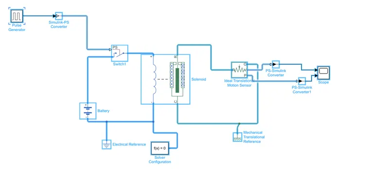
Blocks used in above model are:-
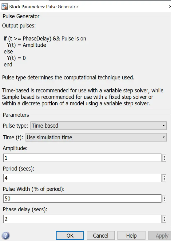
- Pulse Generator: It generates square wave pulses at regular intervals and the parameters like amplitude, period, pulse width and phase delay determines the shape of output pulse.
- Simulink-PS converter: Converts the Simulink input signal to a Physical Signal.
- Switch1: The block represents a switch controlled by an external physical signal. If the external physical signal PS is greater than the threshold, then the switch is closed, otherwise the switch is open.
- Battery: This block models a battery i.e a constant voltage source.
- Electrical Reference: A model must contain at least one electrical reference port (electrical ground).
- Solver Configuration: Defines solver settings to use for simulation.
- Solonoid: This block implements the electrical and mechanical characteristics of a solenoid. A solenoid is a device comprised of a coil of wire, the housing and a moveable plunger (armature). When an electrical current is introduced, a magnetic field forms around the coil which draws the plunger in. More simply, a solenoid converts electrical energy into mechanical work.
- Mechanical Translational Reference: This block represents a mechanical translational reference point, that is, a frame or a ground. Use it to connect mechanical translational ports that are rigidly affixed to the frame (ground).
- Ideal Translational Motion Sensor: This block measures velocity or displacement in a mechanical translational network. The sensor is ideal since it does not account for inertia, friction, delays, energy consumption, and so on.
The physical signal ports V and P report the displacement and velocity, respectively, of port R relative to port C. The measurement is positive when the motion at R is greater than the motion at C. - PS-Simulink converter: Converts the Physical signal to a Simulink input.
- Scope: Display signals generated during simulation.
RESULT:
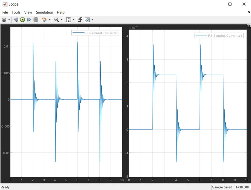
ON running the above doorbell model, We obtain the plot of movement of plunger(ideal mechanical motion sensor) with time.
Simulink model for above doorbell with both condition 1 and 2.
-Model 1: To calculate the voltage corresponding to 25°C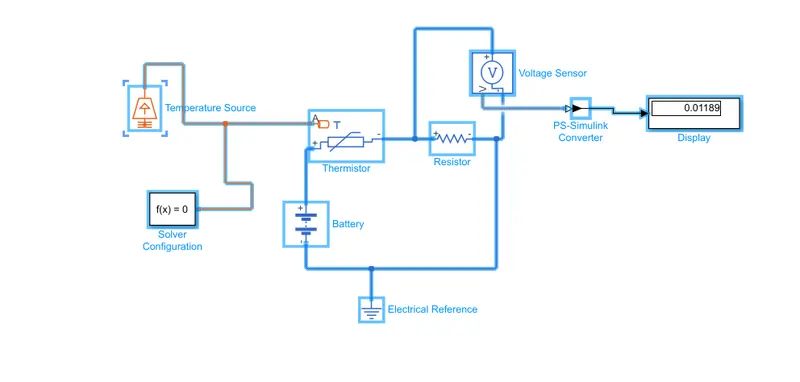
-Model 2: To switch fan on/off based on above output voltage.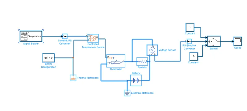
Blocks used in above model are:-
- Temperature Source: This block represents an ideal energy source in a thermal network that can maintain a constant absolute temperature at the port regardless of the heat flow rate.
- Thermistor: A thermistor is a resistance thermometer, or a resistor whose resistance is dependent on temperature. The term is a combination of “thermal” and “resistor”. It is made of metallic oxides, pressed into a bead, disk, or cylindrical shape and then encapsulated with an impermeable material such as epoxy or glass.
- Voltage Sensor: The block represents an ideal voltage sensor, that is, a device that converts voltage measured between any electrical connections into a physical signal proportional to the voltage.Connections + and - are conserving electrical ports through which the sensor is connected to the circuit. Connection V is a physical signal port that outputs voltage value.
- Display: To display the output.
- Signal Builder: This block represents an ideal voltage sensor, that is, a device that converts voltage measured between any electrical connections into a physical signal proportional to the voltage.Connections + and - are conserving electrical ports through which the sensor is connected to the circuit. Connection V is a physical signal port that outputs voltage value.
- Controlled Temperature Source: This block represents an ideal energy source in a thermal network that can maintain a controlled temperature difference regardless of the heat flow rate. The temperature difference is set by the physical signal port S. A positive temperature difference causes the temperature at port B to be greater than the temperature at port A.
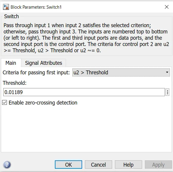
- Switch: This block propagates one of two inputs to its output depending on the value of a third input, called the control input. If the signal on the control (second) input is greater than or equal to the Threshold parameter, the block propagates the first input; otherwise, it propagates the third input.
RESULT:
1) By setting reference temperature at 25°C of temperature source, we get outut voltage of 0.01189 volts.
2) We used this 0.01189 volt as threshold parameter for switch.
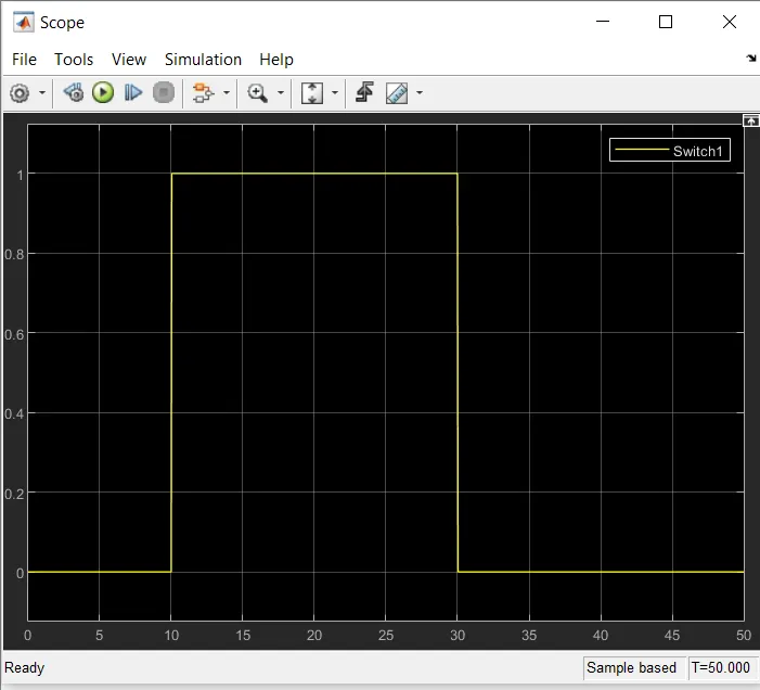
3) We get plot for Fan operating wrt Temperature .
REFERENCE:
- google.com
- Matlab