Week - 4
AIM:
- Implement control logic of a “washing machine” using Stateflow as per given sequence:
- If the power supply is available, the system gets activated
- If the Water supply is not available, stop the process & indicate through LED
- Soaking time should be 200s followed by Washing time of 100s.
- Then rinsing happens for next 20s & dryer runs for 50s
After all the processes have completed turn on the finished LED
2. Make a Simulink chart for the “Gear shift” logic as per below conditions:
Speed Range(kmph) Gear
0 to 15 1
16 to 25 2
26 to 40 3
41 to 60 4
Above 61 5
Give speed input while the simulation is running & display the gear number.
STUDY 1 - Automatic Washing Machine Model
A washing machine (laundry machine, clothes washer, or washer) is a home appliance used to wash laundry. The working principle of a washing machine is centrifugation. Centrifugation is a separation process which uses the action of centrifugal force to promote accelerated settling of particles in a solid-liquid mixture.
It consist of four process:-
- Soaking - Soak Function is used to dip clothes for 200 seconds in detergent water to remove dirt from the clothes.
- Washing - It agitates our clothes in a soapy suds and water for 100 seconds remove any dirt and stains by spinning action.
- Rinsing - Washing machines perform several rinses for 20 seconds after the main wash to remove most of the detergents.
- Drying - the dryer uses a heat exchanger to cool the air and condense the water vapor into either a drain pipe or a collection tank. The drier air is run for 50 seconds through the loop again.
- The control logic and state flow model of washing machine with ON water supply and ON power supply
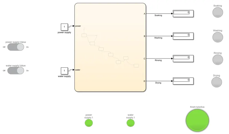
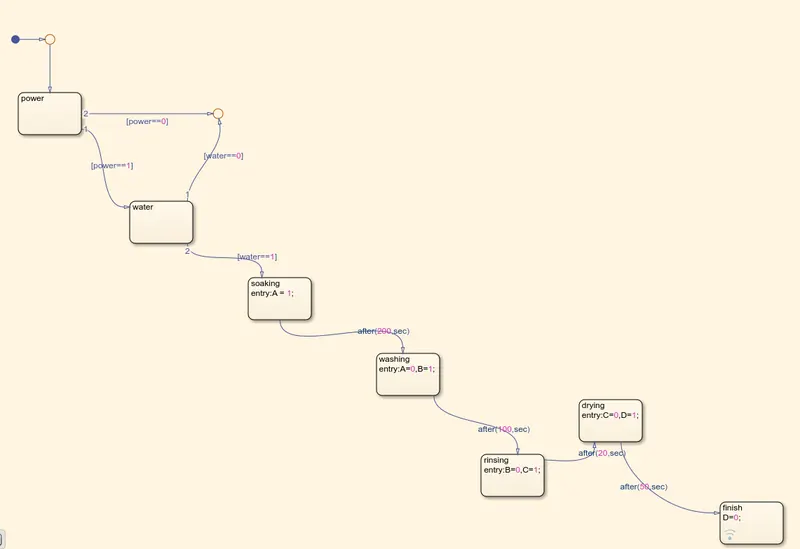
Here,
- Two inputs are given for power supply and water supply.
- Five outputs are provided in which four are used to display the ongoing operation and fifth display FINISH condition.
- The control logic model of washing machine with OFF water supply and ON power supply.
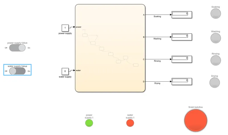
- Here we can see FINISH is not executed because of OFF water supply.
STUDY 2 - Automatic Gear Shift
Automatic transmission has a series of numbers of manual gear settings for the forward gear operation this system uses low-cost microcontrollers to make the accurate decision for shifting the gear up and down by observing the speed, — with 1 being the lowest gear and larger numbers representing higher gears.
- Gear1: It is the most powerful gear, so it is the gear used when starting from a stopped state and also aids to increases torque for difficult terrains like mud or sand.
Use it within the speed range of 0 to 15 km / h. - Gear2: Aids the car in uphill climbing, such as hilly roads, or provides a quick engine boost similar to its function on manual transmissions.
Use it within the speed range of 16 to 25 km / h. - GEAR3: This gear is used to increase the speed further than 2nd gear. Gears of 3rd gear or higher do not have enough power to start a car, so they are not used for starting.
Use it within the speed range of 26 to 40 km / h. - GEAR4: This is a gear used when raising the speed further than 3rd speed.
Use it on a large road such as a national highway when you are traveling at a speed that allows you to get into the flow.
Use it within the speed range of 41 to 60 km / h. - GEAR5: This is a gear used for running at the highest speed such as on expressways.
This gear also used when you want to drive economically because the number of revolutions of the drive shaft that transmits the driving force to the wheels exceeds the engine revolution number.
Use it when the speed is above 20 km / h.
- The control logic and state flow model of Automatic Gear Shift with speed input
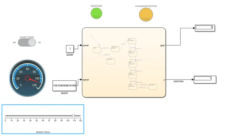
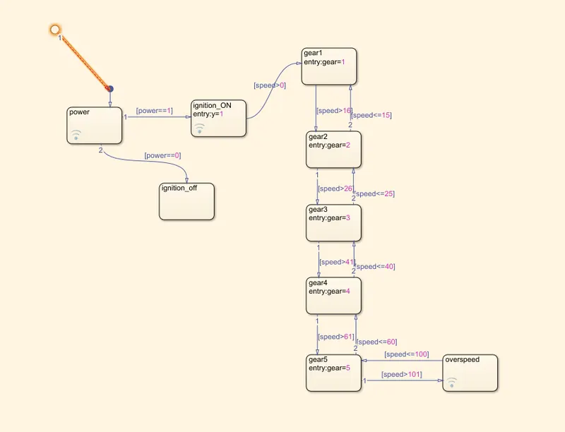
Here,
- Speed and Power is given as input.
- Speed is given by slider block which is connected by Speedometer
- Output is Gear no and Ignition condition.
- Over speed ie speed greater than 100km/hr, is also indicated.
REFERENCE: google.com