Project-1: Powertrain for aircraft in runways
PART A
Q1. SEARCH AND LIST OUT THE TOTAL WEIGHT OF BARIOUS TYPES OF AIRCRAFTS.
SOLUTION:-
Weights of Airplanes
MTOW = Maximum take-off weight, MLW = Maximum landing weight, TOR = Take-off run (SL, ISA+15°, MTOW), LR = Landing run (SL, ISA+15°, MLW)
| Type | MTOW [kg] | MLW [tons] | TOR [m] | LR [m] | ICAO category | FAA category |
|---|---|---|---|---|---|---|
| Antonov An-225 | 640,000 | 591.7 | 3500 | Heavy | Super | |
| Scaled Composites Model 351 Stratolaunch | 589,670 | 3660 | Heavy | Super | ||
| Airbus A380-800 | 575,000 | 394 | 3100 | 1930 | Super | Super |
| Boeing 747-8F | 447,700 | 346.091 | 3100 | 1800 | Heavy | Heavy |
| Boeing 747-8 | 443,613 | 306.175 | 3100 | Heavy | Heavy | |
| Boeing 747-400ER | 412,770 | 295.742 | 3090 | Heavy | Heavy | |
| Antonov An-124-100M | 405,060 | 330 | 2520 | 900 | Heavy | Heavy |
| Boeing 747-400 | 396,900 | 295.742 | 3018 | 2179 | Heavy | Heavy |
| Lockheed C-5 Galaxy | 381,000 | 288.417 | 2530 | 1494 | Heavy | Heavy |
| Boeing 747-200 | 377,840 | 285.700 | 3338 | 2109 | Heavy | Heavy |
| Boeing 747-300 | 377,840 | 260.320 | 3222 | 1905 | Heavy | Heavy |
| Airbus A340-500 | 371,950 | 240 | 3050 | 2010 | Heavy | Heavy |
| Airbus A340-600 | 367,400 | 256 | 3100 | 2100 | Heavy | Heavy |
| Boeing 777F | 347,800 | 260.816 | 2830 | Heavy | Heavy | |
| Boeing 777-300ER | 351,800 | 251.29 | 3100 | Heavy | Heavy | |
| Boeing 777-200LR | 347,450 | 223.168 | 3000 | Heavy | Heavy | |
| Boeing 747-100 | 340,200 | 265.300 | Heavy | Heavy | ||
| Airbus A350-1000 | 308,000 | 233.5 | Heavy | Heavy | ||
| Boeing 777-300 | 299,370 | 237.683 | 3380 | Heavy | Heavy | |
| Boeing 777-200ER | 297,550 | 213.00 | 3380 | 1550 | Heavy | Heavy |
| Airbus A340-300 | 276,700 | 190 | 3000 | 1926 | Heavy | Heavy |
| McDonnell Douglas MD-11 | 273,300 | 185 | 2990 | 1890 | Heavy | Heavy |
| Airbus A350-900 | 270,000 | 175 | 2670 | 1860 | Heavy | Heavy |
| Ilyushin Il-96M | 270,000 | 195.04 | 3115 | 2118 | Heavy | Heavy |
| McDonnell Douglas DC-10 | 256,280 | 183 | 2990 | 1890 | Heavy | Heavy |
| Boeing 787-9 | 254,000 | 192.777 | 2900 | Heavy | Heavy | |
| Boeing 787-10 | 254,000 | 201.849 | Heavy | Heavy | ||
| Airbus A340-200 | 253,500 | 181 | 2990 | Heavy | Heavy | |
| Ilyushin IL-96-300 | 250,000 | 175 | 2600 | 1980 | Heavy | Heavy |
| Airbus A330-300 | 242,000 | 185 | 2500 | 1750 | Heavy | Heavy |
| Airbus A330-200 | 242,000 | 180 | 2220 | 1750 | Heavy | Heavy |
| Lockheed L-1011-500 | 231,300 | 166.92 | 2636 | Heavy | Heavy | |
| Boeing 787-8 | 228,000 | 172.365 | 3300 | 1695 | Heavy | Heavy |
| Lockheed L-1011-200 | 211,400 | Heavy | Heavy | |||
| Ilyushin IL-86 | 208,000 | 175 | Heavy | Heavy | ||
| Boeing 767-400ER | 204,000 | 158.758 | 3414 | Heavy | Heavy | |
| Airbus A300-600R | 192,000 | 140 | 2385 | 1555 | Heavy | Heavy |
| Boeing 767-300ER | 187,000 | 136.08 | 2713 | 1676 | Heavy | Heavy |
| Concorde | 185,000 | 111.1 | 3440 | 2220 | Heavy | Heavy |
| Airbus A300-600 | 163,000 | 138 | 2324 | 1536 | Heavy | Heavy |
| Boeing 767-300 | 159,000 | 136.078 | 2713 | 1676 | Heavy | Heavy |
| Airbus A310-300 | 157,000 | 124 | 2290 | 1490 | Heavy | Heavy |
| Vickers VC10 | 152,000 | 151.9 | Heavy | Heavy | ||
| Boeing 707-320B | 151,000 | 97.5 | Heavy | Heavy | ||
| Boeing 707-320C | 151,000 | 112.1 | Heavy | Heavy | ||
| Douglas DC-8-61 | 147,000 | Heavy | Heavy | |||
| Airbus A310-200 | 142,000 | 123 | 1860 | 1480 | Heavy | Heavy |
| Airbus A400M | 141,000 | 122 | 980 | 770 | Heavy | Heavy |
| Douglas DC-8-32 | 140,000 | Heavy | Heavy | |||
| Douglas DC-8-51 | 125,000 | Medium | Large | |||
| Boeing 757-300 | 124,000 | 101.6 | 2550 | 1750 | Medium | Large |
| Boeing 707-120B | 117,000 | 86.3 | Medium | Large | ||
| Boeing 757-200 | 116,000 | 89.9 | 2347 | 1555 | Medium | Large |
| Boeing 720B | 106,000 | 79.5 | Medium | Large | ||
| Boeing 720 | 104,000 | 79.5 | Medium | Large | ||
| Tupolev Tu-154M | 104,000 | 80 | Medium | Large | ||
| Tupolev Tu-204SM | 104,000 | 87.5 | 2250 | Medium | Large | |
| Convair 880 | 87,500 | Medium | Large | |||
| Boeing 737-900 | 85,000 | 66.36 | 2500 | 1704 | Medium | Large |
| Boeing 737-900ER | 85,000 | 71.35 | 2804 | 1829 | Medium | Large |
| Boeing 727-200 Advanced | 84,000 | 70.1 | Medium | Large | ||
| Airbus A321-100 | 83,000 | 77.8 | 2200 | 1540 | Medium | Large |
| Boeing 737-800 | 79,000 | 65.32 | 2308 | 1634 | Medium | Large |
| Boeing 727-200 | 78,000 | 68.1 | Medium | Large | ||
| McDonnell-Douglas MD-83 | 73,000 | 63.28 | Medium | Large | ||
| Boeing 727-100 | 72,500 | 62.4 | Medium | Large | ||
| Boeing 727-100C | 72,500 | 62.4 | Medium | Large | ||
| McDonnell-Douglas MD-90-30 | 71,000 | 64.41 | 2165 | 1520 | Medium | Large |
| de Havilland Comet 4 | 70,700 | Medium | Large | |||
| Boeing 737-700 | 70,000 | 58.06 | 1921 | 1415 | Medium | Large |
| Airbus A320-100 | 68,000 | 66 | 1955 | 1490 | Medium | Large |
| Boeing 737-400 | 68,000 | 54.9 | 2540 | 1540 | Medium | Large |
| de Havilland Comet 3 | 68,000 | Medium | Large | |||
| Boeing 377 | 67,000 | Medium | Large | |||
| Boeing 737-600 | 66,000 | 54.66 | 1796 | 1340 | Medium | Large |
| Airbus A220-300 | 65,000 | 57.61 | 1890 | 1494 | Medium | Large |
| Hawker Siddeley Trident 2E | 65,000 | Medium | Large | |||
| Airbus A319 | 64,000 | 62.5 | 1850 | 1470 | Medium | Large |
| Boeing 737-300 | 63,000 | 51.7 | 1939 | 1396 | Medium | Large |
| Boeing 737-500 | 60,000 | 49.9 | 1832 | 1360 | Medium | Large |
| Airbus A220-100 | 59,000 | 50.80 | 1463 | 1356 | Medium | Large |
| Airbus A318 | 59,000 | 57.5 | 1375 | 1340 | Medium | Large |
| Boeing 717-200HGW | 55,000 | 47.174 | 1950 | Medium | Large | |
| Douglas DC-7 | 55,000 | Medium | Large | |||
| de Havilland Comet 2 | 54,000 | Medium | Large | |||
| Boeing 717-200BGW | 50,000 | 46.265 | 1950 | Medium | Large | |
| de Havilland Comet 1 | 50,000 | Medium | Large | |||
| Douglas DC-6A | 48,600 | Medium | Large | |||
| Douglas DC-6B | 48,500 | Medium | Large | |||
| Embraer 190 | 48,000 | 43 | 2056 | 1323 | Medium | Large |
| Caravelle III | 46,000 | Medium | Large | |||
| Fokker 100 | 46,000 | 39.95 | 1621 | 1350 | Medium | Large |
| Douglas DC-6 | 44,000 | Medium | Large | |||
| Avro RJ-85 | 42,000 | 36.74 | Medium | Large | ||
| Handley Page Hermes | 39,000 | Medium | Large | |||
| Embraer 175 | 37,500 | 32.8 | 2244 | 1304 | Medium | Large |
| Bombardier CRJ900 | 36,500 | 33.345 | 1778 | 1596 | Medium | Large |
| Embraer 170 | 36,000 | 32.8 | 1644 | 1274 | Medium | Large |
| Bombardier CRJ700 | 33,000 | 30.39 | 1564 | 1478 | Medium | Large |
| Douglas DC-4 | 33,000 | Medium | Large | |||
| Vickers Viscount 800 | 30,400 | Medium | Large | |||
| Bombardier Q400 | 28,000 | 28.01 | 1219 | 1295 | Medium | Large |
| Bombardier CRJ200 | 23,000 | 21.319 | 1918 | 1479 | Medium | Large |
| ATR 72-600 | 22,800 | 22.35 | 1333 | 914 | Medium | Large |
| Saab 2000 | 22,800 | 21.5 | 1300 | Medium | Large | |
| Embraer ERJ 145 | 22,000 | 19.3 | 2270 | 1380 | Medium | Large |
| ATR 42-500 | 18,600 | 18.3 | 1165 | 1126 | Medium | Small |
| Saab 340 | 13,150 | 12.930 | 1300 | 1030 | Medium | Small |
| Embraer 120 Brasilia | 11,500 | 11.25 | 1560 | 1380 | Medium | Small |
| BAe Jetstream 41 | 10,890 | 10.570 | 1493 | 826 | Medium | Small |
| Learjet 75 | 9,752 | 8.709 | 1353 | 811 | Medium | Small |
| Pilatus PC-24[ | 8,300 | 7.665 | 893 | 724 | Medium | Small |
| Embraer Phenom 300 | 8,150 | 7.65 | 956 | 677 | Medium | Small |
| Beechcraft 1900D | 7,765 | 7.605 | 1036 | 853 | Medium | Small |
| Cessna Citation CJ4 | 7,761 | 7.103 | 1039 | 896 | Medium | Small |
| de Havilland Hercules | 7,000 | Medium | Small | |||
| Embraer Phenom 100 | 4,800 | 4.43 | 975 | 741 | Light | Small |
Q2. IS THERE ANY DIFFERENCE BETWEEN GROUND SPEED AND AIR SPEED?
SOLUTION:-
Yes there is difference between the ground and the air speed.
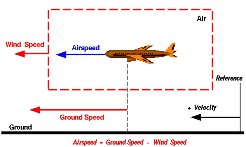
With reference to the above image, I'm going to differentiate the ground speed and the airspeed.
Ground speed is the aircraft speed relative to the ground that it explains how speed can aircraft travel in the ground. It is not dependent on the airspeed.
Here Airspeed is the relative motion between the object and the air. This is also an important parameter for aerodynamic lift generation. This air speed of the object cannot be measured directly from the ground, it depends upon the ground and the wind speed, in fact it is the "vector difference" between the ground and wind speed. (As shown in the above figure).
On a perfectly still day, the airspeed is equal to the ground speed. But if the wind is blowing in the same direction that the aircraft is moving, the airspeed will be less than the ground speed.
Q3. WHY IS IT NOT RECOMMENDED TO USE AIRCRAFT ENGINE POWER TO MOVE IT ON THE GROUND AT AIRPORT?
SOLUTION:-
Generally the aircafts can't move in the reverse direction because the aircraft engines are not designed to move in the reverse direction.We can move reverse by backward thrust but with the high risk. Aircrafts can taxi in the Airports by smaller thrust by checking with the ground controller's taxi map.
To move in the reverse direction push-back trucks are used.
Taxiing: is the movement of an aircraft on the ground, under its own power. An airplane uses taxiways to taxi from one place on an airport to another; for example, when moving from a hanger to the runway. The term "taxiing" is not used for the takeoff roll and landing rollout.
Towing or push-back: Pushback means the movement of an aircraft from a nose-in parking stand using the power of a specialised ground vehicle attached to or supporting the nose landing gear.
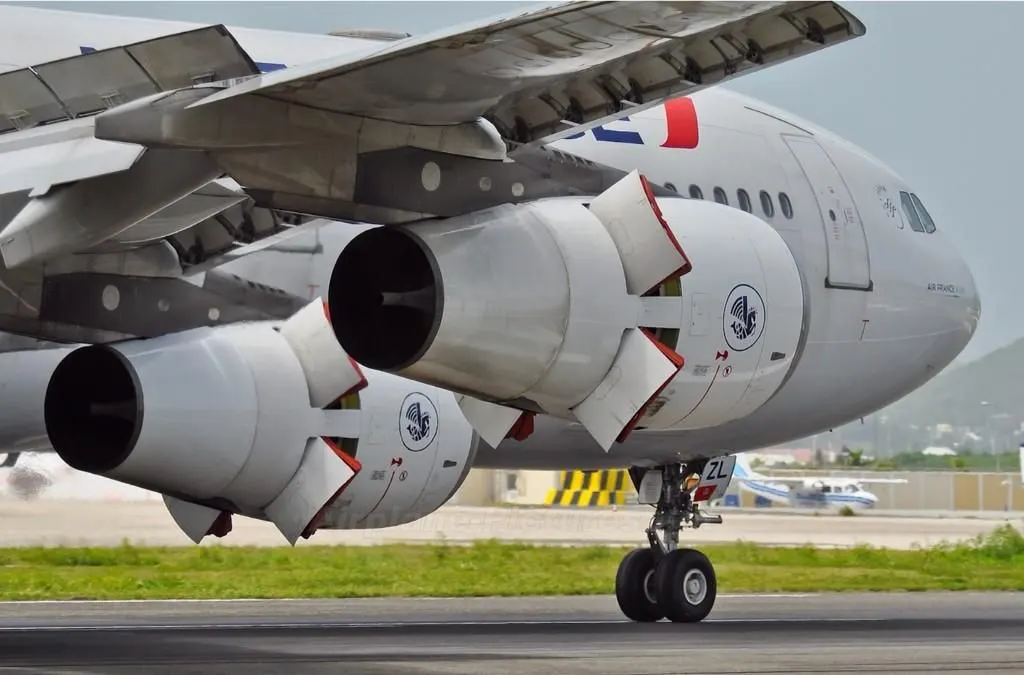
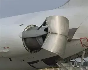
An aircraft towed by a tug Backward thrust of an Aircraft.
The ‘traditional’ method of allowing the ground vehicle to move an aircraft is to attach it to the aircraft nose landing gear by means of a towbar. These must be approved for use with a particular aircraft type and clearly marked as such since there is no universal towbar specification. An alternative method which is becoming more common for towing is the use of a specialised vehicle called a ‘towbarless tug’. This positions two low level ‘arms’ either side of the aircraft nose landing gear and these are used to engage with the aircraft gear leg and raise it slightly off the ground.
Resions for not recommended to use aircraft engine power to move it on the ground at Airport are:
- It is not easy to taxi an airplanes in a busy airports because of the longer wings. When you have another aircraft packed close to you it is quite difficult to judge the distance between your ings and packed aircrafts. Having a push-back trucks moves safer distance with a enough space for you without aircraft engines.
- The backwords trust would do damage the jetsway or throw up loose debris on the thermac which would end up getting sucked up in a running jet engine of another plain. That's why we see no reverse thrusters sign at the gates.
- Using an aircraft engine power causes a lot of noise. And having huge risk of jet blast and surroundings.
- Aircraft Pilots have very limited view of their surroungings and may fail to notice the ground vehicle or even another aircraft. The tug operator can see everything clearly
Q4. HOW AN AIRCRAFT IS PUSHED TO RUNWAY WHEN ITS TO TAKE OFF?
SOLUTION:-
The process of pushing an aircraft to the runway when its ready to take-off is called as Pushback.It is an airport procedure during which an aircraft is pushed backwards away from an airport gate towards the runway by external power. Pushbacks are carried out by special, low-profile vehicles called pushback tractors or tugs.
Although many aircraft are capable of moving themselves backwards on the ground using reverse thrust (a procedure referred to as a powerback), the resulting jet blast or prop wash might cause damage to the terminal building or equipment. Engines close to the ground may also blow sand and debris forward and then suck them into the engine, causing damage to the engine. A pushback is therefore the preferred method to move the aircraft away from the gate.
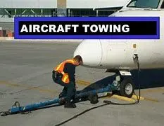
Pushbacks at busy aerodromes are usually subject to ground control clearance to facilitate ground movement on taxiways. Once clearance is obtained, the pilot will communicate with the tractor driver (or a ground handler walking alongside the aircraft in some cases) to start the pushback. To communicate, a headset may be connected near the nose gear.
Since the pilots cannot see what is behind the aircraft, steering is done by the pushback tractor driver and not by the pilots. Depending on the aircraft type and airline procedure, a bypass pin may be temporarily installed into the nose gear to disconnect it from the aircraft's normal steering mechanism.
Once the pushback is completed, the towbar is disconnected, and any bypass pin removed. The ground handler will show the bypass pin to the pilots to make it clear that it has been removed. The pushback is then complete, and the aircraft can taxi forward under its own power.
Q5. LEARN ABOUT TAKE OFF POWER, TYRE DESIGN, ROLLING RESISTANCE, TYRE PRESSURE, BRAKE FORCES WHEN LANDING.
SOLUTION:-
Takeoff
It is the phase of flight in which an aircraft goes through a transition from moving along the ground (taxiing) to flying in the air, usually starting on a runway. Take off power can be predicted using a simple measure of the acceleration of the aircraft along the runway based on force equilibrium.
The forces involved will be,
T → Thrust of propulsion system pushing aircraft along the runway.
D → Aerodynamic Drag of vehicle resisting the aircraft motion.
F → Rolling resistance friction due to the contact of wheels or skids on the ground.
During the take-off run, the imbalance in these forces will produce an acceleration along the runway.
m*(dv/dt)=T-D-F
where, dv/dt is the acceleration along the runway and m is the mass of the vehicle.
The procedure for take-off will be that the vehicle will accelerate until it reaches a safe initial flying speed. The pilot can then rotate the vehicle to an attitude to produce a climb lift and it will ascend from the ground. The determination of this safe flying speed or rotation speed, Vr is a critical factor in determining take-off performance. Take-off rules vary slightly depending on the aircraft category.
For Small commuter aircraft
Vr=1.1×VSTALL
or
Vr=1.05×VControl
whichever is great.
`VSTALL = sqrt (W/(0.5* CLmax ⋅ ρ ⋅ S)`,
where S →displacement
Takeoff Field Length
The required length of the runway will be the sum of the distance required to get to rotation speed and the extra length required to clear a 50ft obstacle or the extra length required to allow for rapid braking if the pilot decides to abort take-off at the decision speed V1.
This length will typically be considerably longer than the distance required to achieve rotation (flying) speed. A rough approximation is that the runway total length is around S1=2.
Therefore,
Takeoff power = force * displacement
= (m⋅dv/dt)⋅2⋅S1=(T-D-F)⋅S1
Rolling Resistance
The friction between aircraft and runway will be proportional to the normal force exerted by the aircraft on the runway.
F=μ(W−L)
The normal force will be the difference between the Weight of the aircraft and the Lift, the friction coefficient will be typical of a magnitude of 0.02 for a standard runway
Braking Forces in Landing
The landing run can be calculated similarly to the take-off distance. The aim is again to minimise the distance.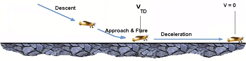
The touchdown velocity should be approximately the stall speed of the aircraft in the landing configuration. This will be achieved by a pitch manoeuvre during the flare portion of the approach which increases drag and decelerates the aircraft to minimum flying speed. The deceleration on the landing roll from VTD to V0 will be accomplished by braking and reverse thrust. This can be solved by the average acceleration approach that was used to estimate the take-off roll.
m⋅(dv/dt)= -T-D-F
The negative acceleration or deceleration value will be based on the friction coefficient for maximum braking and the value of reverse thrust.
Aircraft Tyre design
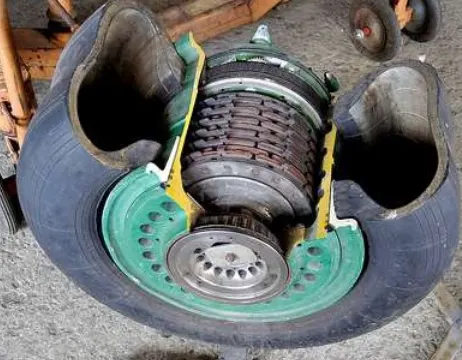
Aircraft wheels are an important component of a landing gear system. With tires mounted upon them, they support the entire weight of the aircraft during taxi, takeoff, and landing. The typical aircraft wheel is lightweight, strong, and made from aluminium alloy. Some magnesium alloy wheels also exist. Early aircraft wheels were of single-piece construction, much the same as the modern automobile wheel.
As aircraft tires were improved for the purpose they serve, they were made stiffer to better absorb the forces of landing without blowing out or separating from the rim. Stretching such a tire over a single piece wheel rim was not possible. A two-piece wheel was developed.
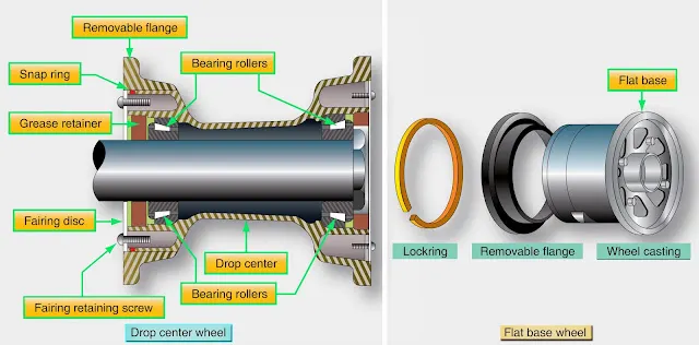
Early two-piece aircraft wheels were essentially one-piece wheels with a removable rim to allow mounting access for the tire. These are still found on older aircraft. Later, wheels with two nearly symmetrical halves were developed. Nearly all modern aircraft wheels are of this two-piece construction
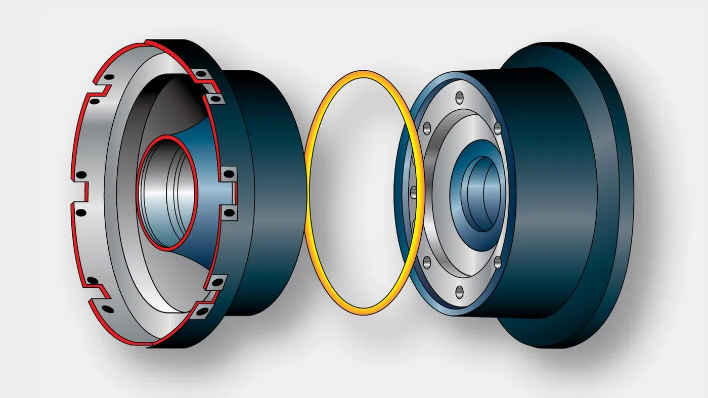
two-piece aircraft wheel found on a modern airliner
The typical modern two-piece aircraft wheel is cast or forged from aluminium or magnesium alloy. The halves are bolted together and contain a groove at the mating surface for an o-ring, which seals the rim since most modern aircraft utilize tubeless tires. The bead seat area of a wheel is where the tire actually contacts the wheel. It is the critical area that accepts the significant tensile loads from the tire during landing. To strengthen this area during manufacturing, the bead seat area is typically rolled to pre-stress it with a compressive stress load. Modern tyres are much more rigid, due to the load-bearing requirements, which results in the wheels having to be of two-piece construction.
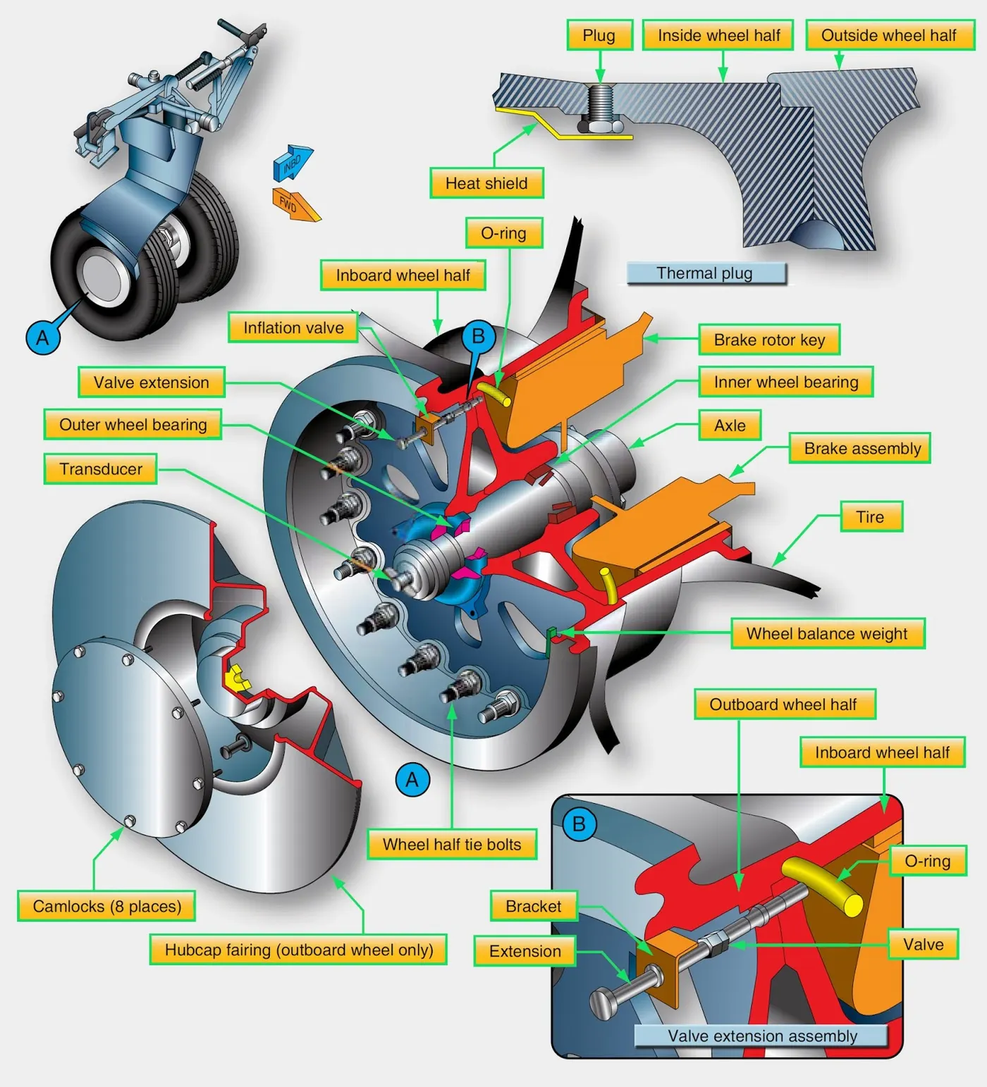
Aircraft Tyre Pressure
Aircraft tires generally operate at high pressures, up to 200 psi (14 bar or 1,400 kPa) for airliners, and even higher for business jets. The main landing gear was typically inflated to 232 psi (16.0 bar), whilst its tail bumper gear tires were as high as 294 psi (20.3 bar). The high pressure and weight load tyres were a significant factor.
Tests of airliner aircraft tires have shown that they can sustain pressures of a maximum of 800 psi (55 bar; 5,500 kPa) before bursting. During the tests, the tires have to be filled with water, to prevent the test room from being blown apart by the energy that would be released by gas when the tire bursts.
Aircraft tires are usually inflated with nitrogen to minimize expansion and contraction from extreme changes in ambient temperature and pressure experienced during flight. Dry nitrogen expands at the same rate as other dry atmospheric gases (normal air is about 80% nitrogen), but common compressed air sources may contain moisture, which increases the expansion rate with temperature.
The requirement that an inert gas, such as nitrogen, be used instead of air for inflation of tires on certain transport category aeroplanes was prompted by at least three cases in which the oxygen in air-filled tires had combined with volatile gases given off by a severely overheated tire and exploded upon reaching autoignition temperature. The use of inert gas for tire inflation eliminates the possibility of a tire explosion
PART-B
Q6. A. WITH NECESSARY ASSUMPTIONS, CALCULATE THE FORCE AND POWER REQUIRED TO PUSH/PULL AN AIRCRAFT BY A TOWING VEHICLE.
B. DEVELOP THE MODEL FOR THE CALCULATED FORCE AND POWER USING SIMULINK.
SOLUTION:-
Assumptions :
Weight of the Aircraft (Airbus A-380) = 575000kg
Rolling Resistance Coecient of an aircraft tire(μrr) = 0.004
Wight of the Towing Tractor = 50000kg
Rolling Resistance Coecient of Towing Vehicle(μrr) = 0.001
Then,
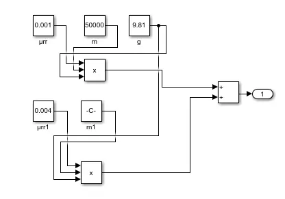
Rolling Resistance Force of Tow Tractor = μrr × m. g = 0.001 × 50000 × 9.81 = 0.49KN
Rolling Resistance Force of aircraft = μrr × m. g = 0.004 × 575000 × 9.81 = 22.56KN
Total Rolling Resistance Force = Rolling Resistance Force of aircraft + Towing Tractor = 0.49 + 22.56
Total Rolling Resistance Force = 23.05KN
Air Drag Force :The drag force is the force that occures due to the Air Strike effect on the vehicle when it moves. The vehicle moves through a air medium of particular dencsity value with certain speed this causes the air strike against the vehicle body and it causesDrag Force on the vehicle.
The Aerodynamic Drag is given by the following expression
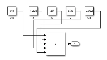
fad = 0.5* ρ *A *V^2 *Cd
Where,
ρ = Density of Air Medium
A = Frontal Area Of the Vehicle which strike the Air
V = Velocity with which the vehicle moves
Cd = Coecient of Dragwhich varies different shapes of the frontal area.
Calculation:
Let us assume,
The Velocity of the Aircraft while Towing = 30KMPH = 8.33m/s
Density of Air medium(ρ) = 1.225
The Frontal area of the Aircraft(A) = 20m^2
The Coecient of Drag of the Aircraft = 0.026
Air drag force = 0.5*rho*A*V^2*Cd = 0.022KN
The Air Drag Force of the Aircraft = 0.022KN
Therefore the total force that the motor needs to overcome = Rolling Resistance of the aircraft + Drag Force acting on the Aircraft,
Total forces acting = 23.05 + 0.022
The Total Force that the Motor needs to overcome in order to push/pull the Aircraft = 23.07KN
The Power required to push/pull the airplane :
The power required by the motor is given by the velocity with which the towing operation takes place.
The average speed of push/pull = 20 kmph = 5.5m/s
Power required by the motor = Total Force*Velocity = 23.07*5.5
Power Required by The Motor = 126.8kw
MODELING THE ABOVE IN MATLAB SIMULINK:
MODEL:-
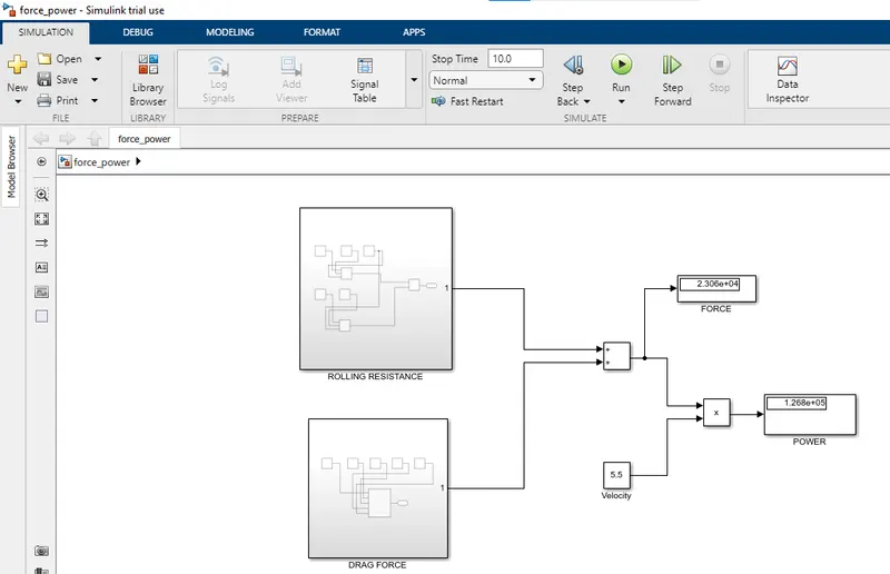
The above model comprises of two subsystems,
ROLLING RESISTANCE:-
DRAG FORCE:-
CONCLUSION:-
Hence, we can see the calculated value and simulated values are more or less equal to each other and thus our modeling is successfull.
Q7. A. DESIGN AN ELECTRIC POWERTRAIN WITH TYPE OF MOTOR, IT'S POWER RATING, AND ENERGY REQUIREMENT TO FULFILL AIRCRAFT TOWING APPLICATION IN SIMULINK. ESTIMATE THE DUTY CYCLE RANGE TO CONTROL THE AIRCRAFT SPEED FROM ZERO TO HIGHEST. MAKE ALL REQUIRED ASSUMPTIONS. PREPARE A TABLE OF ASSUMED PARAMETERS. DRAW A BLOCK DIAGRAM OF POWERTRAIN.
B. ALSO, DESIGN THE PARAMENTERS IN EXCEL SHEET.
SOLUTION:-
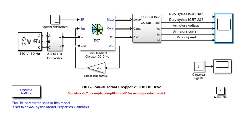
Here, we will be taking DC7 motor as an example :-
Description
The 200 HP DC motor is separately excited with a constant 150 V DC field voltage source. The armature voltage is provided by an IGBT converter controlled by two PI regulators. The converter is fed by a 515 V DC bus obtained by rectification of a 380 V AC 50 Hz voltage source. In order to limit the DC bus voltage during dynamic braking mode, a braking chopper has been added between the diode rectifier and the DC7 block.
The first regulator is a speed regulator, followed by a current regulator. The speed regulator outputs the armature current reference (in p.u.) used by the current controller in order to obtain the electromagnetic torque needed to reach the desired speed. The speed reference change rate follows acceleration and deceleration ramps in order to avoid sudden reference changes that could cause armature over-current and destabilize the system. The current regulator controls the armature current by computing the appropriate duty ratios of the 5 kHz pulses of the four IGBT devices (Pulse Width Modulation). For proper system behaviour, the instantaneous pulse values of IGBT devices 1 and 4 are opposite to those of IGBT devices 2 and 3. This generates the average armature voltage needed to obtain the desired armature current. In order to limit the amplitude of the current oscillations, a smoothing inductance is placed in series with the armature circuit.
OUTPUT:-
Simulation
Before starting the simulation, set the initial bus voltage to 515 V via the GUI block ('Initial States Setting' button and 'Cbus' variable).
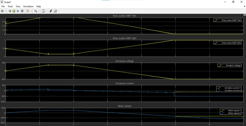
Start the simulation. You can observe the motor armature voltage and current, the four IGBT pulses and the motor speed on the scope. The current and speed references are also shown.
The motor is coupled to a linear load, which means that the mechanical torque of the load is proportional to the speed.
The speed reference is set at 500 rpm at t = 0 s. Observe that the motor speed follows the reference ramp accurately (+400 rpm/s) and reaches steady state around t = 1.3 s.
The armature current follows the current reference very well, with fast response time and small ripples. Notice that the current ripple frequency is 5 kHz.
At t = 2 s, speed reference drops to -1184 rpm. The current reference decreases to reduce the electromagnetic torque and causes the motor to decelerate with the help of the load torque.
At t = 2.2 s, the current reverses in order to produce a braking electromagnetic torque (dynamic braking mode). This causes the DC bus voltage to increase.
At t = 3.25 s, the motor reaches 0 rpm and the load torque reverses and becomes negative. The negative current now produces an accelerating electromagnetic torque to allow the motor to follow the negative speed ramp (-400 rpm/s). At t = 6.3 s, the speed reaches -1184 rpm and stabilizes around its reference.
CONCLUSION:-
The parameters assumed for designing this vehicle is taken from online references
S.No. Assumed Parameters Assumed Values
1. Weight of the Aircraft 575000 kg
2. Weight of the Towing Tractor 50000 kg
3. Rolling Resistance Coefficient of Aircraft 0.004
4. Rolling Resistance Coefficient of Towing Tractor 0.001
5. The velocity of the Aircraft while Towing 8.33 m/s
6. Density of Air medium(rho) 1.225 kg/m^3
7. The Frontal area of the Aircraft 20 m^2
8. The Coefficient of Drag of the Aircraft 0.026
9. Towing Tractor Gear ratio(G- for high torque output) 11
10. Towing Tractor tyre radius(r) 0.635 m
11. Operational time of the Towing for one cycle 0.33 Hour
12. The Battery Armature Voltage 350 V
13. The Battery Armature Current 350 A
14. The Motor Terminal Voltage for full power output 630 V @ motor terminals
15. Power converters used Bidirectional DC-DC Boost Converter
16. The maximum duty ratio for acieving full power 70%
Assuming the operational time of the Towing Truck is around 20 minuts for one cycle
20 minutes = 0.33 hour
Energy(kwh) = power(kw)*Time(h) = 162.8*0.33
Energy(kwh) = 53.7 kwh
Therefore the battery must be able to store the energy 41.8 kwh and should deliver the energy throughout the run time in order for the motor to produce the 1.32 KNm of torque instantaneously. Thus the storage of energy in batteries with high performance Ultracapacitors are selected to fulfill the required power deliver.
Motor Selection:
Here we have selected a BLDC Motor type that has a power rating of 126.8kw and with the gear ratio and the transmission it should be able to deliver 1.32KNm of torque instantaneously.
The Battery Armature Voltage (V) 350 V
The Battery Armature Current (A) 350 A
Power Converter:
A boost converter (step-up converter) is a DC-to-DC power converter that steps up voltage (while stepping down current) from its input (supply) to its output (load). It is a class of switched-mode power supply (SMPS) containing at least two semiconductors (a diode and a transistor) and at least one energy storage element: a capacitor, inductor, or the two in combination. To reduce voltage ripple, filters made of capacitors (sometimes in combination with inductors) are normally added to such a converter's output (load-side filter) and input (supply-side filter).
Speed Control of the Vehicle:
The Electric Vehicle uses power from the battery source to drive the motor and then further to drive the wheels in order to move the vehicle. The speed and torque generated from the motor is very important to drive the vehicle as per the driver's desire. If we connect the battery directly to the motor the motor will spin with a speed and torque characteristics which will be based on the full power of the battery voltage. We does not require full power in all the driving conditions so we need to adopt a power controller between the bettery and the motor so that the motor speed may be controlled by the driver to drive the vehicle as desired. For controlling the vehicle power we use the soft switching operation technique here. The amount of power can be controlled by changing the Duty Cycle value. Considering the losses we take 70% of the duty cycle to deliver the maximum power of the motor.
Motor Terminal Voltage = Armature Voltage * Duty Cycle = 900*0.7
With 70% Duty Cycle the voltage at motor terminals = 630V, Which gives the full power with all the gearings instantaneously. Thus by varying the Duty Cycle value the speed of the vehicle is controlled.
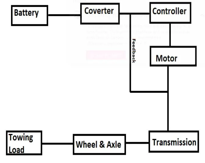
Block Diagram of Powertrain:
Conclusion:
The reference Aircraft taken here is the Heavy Aircraft build and so our designed towing tractor is a heavy duty operational vehicle.The power requirements are calculated for the particular load to be pushed/pulled and to achieve this power at the motor output, the motor type and its voltage at the terminals are discussed.
Then the power converters are used to upscale the battery armature voltage to thr desired high voltage value so that the motor may spin at full power and required torque can be achieved using a Bidirectional DC-DC Converter. Finally the speed control of the vehicle is done with switching techniques where the Duty Cycle adjustment can change the motor speed from the minimum to maximum.