Project-1: Powertrain for aircraft in runways
AIM:
Part A:
1. Search and list out the total weight of various types of aircrafts.
2. Is there any difference between ground speed and air speed?
3. Why is it not recommended to use aircraft engine power to move it on the ground at Airport?
4. How an aircraft is pushed to runway when its ready to take off?
5. Learn about take off power, tyre design, rolling resistance, tyre pressure, brake forces when landing.
Part B:
6. A. With necessary assumptions, calculate the force and power required to push / pull an aircraft by a towing vehicle.
B. Develop the model for the calculated force and power using Simulink.
7. A. Design an electric powertrain with type of motor, it’s power rating, and energy requirement to fulfill aircraft towing application in Simulink. Estimate the duty cycle range to control the aircraft speed from zero to highest. Make all required assumptions. Prepare a table of assumed parameters. Draw a block diagram of powertrain.
(Hint :DC7 Block)
B. Also, Design the parameters in excel sheet.
PART A)
1) the total weight of various types of aircrafts.
1)manufacturer empty weight (MEW)
Also called Manufacturer's Weight Empty (MWE) or Licensed Empty Weight
It is the weight of the aircraft "as built" and includes the weight of the structure, power plant, furnishings, installations, systems and other equipment that are considered an integral part of an aircraft.
This excludes any baggage, passengers, or usable fuel.
2)zero fuel weight (ZFW)
This is the total weight of the airplane and all its contents (including unusable fuel), but excluding the total weight of the usable fuel on board.
As a flight progresses and fuel is consumed, the total weight of the airplane reduces, but the ZFW remains constant.
Maximum zero fuel weight (MZFW) is the maximum weight allowed before usable fuel and other specified usable agents (engine injection fluid, and other consumable propulsion agents) are loaded.
3)operating empty weight(OEW) (Roughly equivalent to basic empty weight on light aircraft)
It is the basic weight of an aircraft including the crew, all fluids necessary for operation such as engine oil, engine coolant, water, unusable fuel and all operator items and equipment required for flight but excluding usable fuel and the payload.
4)payload
It is the carrying capacity of an aircraft. It includes cargo, people, extra fuel. In the case of a commercial airliner, it may refer only to revenue-generating cargo or paying passengers.
5)maximum take off weight (MTOW)
This is the maximum weight at which the pilot of the aircraft is allowed to attempt to take off.
6)regulated take off weight(RTOW)
Depending on different factors (e.g. flap setting, altitude, air temperature, length of runway), RTOW or maximum permissible takeoff weight varies for each takeoff. It can never be higher than MTOW.
7)maximum landing weight (MLW)
This maximum weight at which an aircraft is permitted to land.
The following image depicts takeoff weight components.
8)maximum ramp weight (MRW)
also called maximum taxi weight (MTW)
It is the maximum weight authorized for maneuvering (taxiing or towing) an aircraft on the ground.
9)aircraft gross weight
It is the total aircraft weight at any moment during the flight or ground operation. This decreases during flight due to fuel and oil consumption.
2)
AIR SPEED VERSES GROUND SPEED:
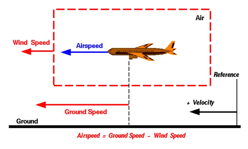
true airspeed is simply the speed at which an aircraft is moving relative to the air it is flying in. As such, it’s also the speed at which the air is flowing around the aircraft’s wings.
Ground speed is the aircraft’s speed relative to the ground. One thing that should be noted here is that it’s its horizontal rather than vertical speed – an aircraft climbing completely vertically would have a ground speed of zero.
In other words, while airspeed is what determines whether there is enough airflow around an aircraft to make it fly, ground speed is what determines how fast an aircraft will get to its destination.
WIND EFFECT ON GROUND SPEED:
The relationship between airspeed and ground speed is fairly simple. Ground speed is simply the sum of airspeed and wind speed.
If the aircraft is flying in the same direction as the wind is blowing, the aircraft experiences tailwind, and its ground speed is higher than its airspeed. On the other hand, if the wind is blowing against the direction the aircraft is traveling in, the aircraft experiences headwind, and its ground speed is lower than its airspeed.
Let us consider the actual example, imagine an aircraft that cruises at an airspeed of 500 miles per hour that has to cover a ground distance of 2,000 miles.
If there is no wind at all, then both the aircraft’s airspeed and ground speed would be the same 500 miles per hour, and the aircraft would reach its destination in four hours.
If there was a 100 miles per hour headwind – wind blowing against the aircraft’s direction of travel – the aircraft would still be traveling at an airspeed of 500 miles per hour. However, its ground speed would be just 400 miles per hour (100 miles per hour slower than its airspeed). And as such, it would take the aircraft five hours to reach its destinations.
Finally, if there was a 100 miles per hour tailwind – wind blowing in the same direction as the aircraft’s travel – the aircraft would still be traveling at an airspeed of 500 miles per hour, but its ground speed would be 100 miles faster. And, at 600 miles an hour, the aircraft would reach its destination in just three hours and twenty minutes.
The above is the reason why some flights go “out of their way” to avoid headwinds or catch tailwinds.
TYPES OF AIRSPEED:
Above we talked about true airspeed. However, pilots commonly use three different types of airspeed: indicated airspeed, calibrated airspeed, and true airspeed.
Indicated airspeed is an airspeed that is calculated directly off an aircraft’s pitot-static system. It’s the calculated off the aircraft’s dynamic pressure – the difference between its total pressure and static pressure.
The dynamic pressure depends not only on the aircraft’s speed, but also on the density of the air it is flying in. As such, the higher the aircraft flies – and the lower the air density as a result – the bigger the difference between indicated and true airspeed is.
Calibrated airspeed is indicated airspeed adjusted for a variety of errors.
Just as an example, one of the things it’s adjusted for is the flap position. The reason for that is that at different flap positions, air flows differently around the pitot-static system and affects the indicated airspeed readings.
True airspeed is the actual speed at which an aircraft is moving relative to the air it is traveling in. It’s calibrated airspeed adjusted for the the exact conditions (altitude, air temperature, etc.) that the aircraft is flying in.
DIAGRAMATIC REPRESENTATION OF AIRSPEED
Why is it not recommended to use aircraft engine power to move it on the ground at Airport.
Taxiing refers to the movement of an aircraft on the ground, under its own power. The aircraft moves on wheels. An airplane uses taxiways to taxi from one place on an airport to another; for example, when moving from a terminal to the runway.
The aircrafts always moves on the ground following the yellow lines, to avoid any collision with the surrounding buildings, vehicles or other aircrafts. The taxiing motion has a speed limit. Before making a turn, the pilot reduces the speed further to prevent tire skids. Just like cars, there is a certain list of priorities during taxiing. The aircrafts that are landing or taking off have higher priority. The other aircrafts have to wait for these aircrafts before they start or continue taxiing.
The thrust to propel the aircraft forward comes from its propellers or jet engines. Steering is achieved by turning a nose wheel or tail wheel/rudder; the pilot controlling the direction travelled with their feet. The use of engine thrust near terminals is restricted due to the possibility of jet blast damage. This is why the aircrafts are pushed back from the buildings by a vehicle before they can start their own engines for taxiing.
3)
the jet engine is not used for primary thrust for taxing because large amount of fuel is wasted. as the fuel cost is mojor consideration in aviation thus many aircraft companies are switching to taxing to save fuel and to reduce emission.
4)
STEPS TO BE FOLLOWED WHEN AN AIRCRAFT IS READY TO TAKE OFF:
- The pilot parks the aircraft in exactly the right place. Usually with the help of an automatic system, but occasionally guided by a marshaller waving two paddles or wands. Dozens of handling personnel are already standing by to perform a whole range of tasks simultaneously.
- As soon as the aircraft is stationary and the engines are switched off, the first priority is to disembark the passengers as quickly as possible. The apron handler places chocks in front of the wheels and connects the ground power. Meanwhile, the passenger bridge manoeuvres up to the door and a belt loader rolls up to the cargo hold. Luggage is unloaded and transferred to the terminal on baggage carts.
- Refuelling begins, usually from a hydrant at the stand. A hose is attached to this from a special vehicle called a dispenser, with the other side connected to the fuel tank in the wing.
- Now it is time to service the aircraft. The caterer loads new meals and takes away the food waste and used cutlery and crockery. Other activities include draining the lavatories, replacing the headrest covers, removing rubbish and distributing fresh blankets and in-flight magazine.
- A specialist team – or sometimes the crew themselves – cleans the cabin so that the new passengers board a pristine aircraft.
- Meanwhile, specialists from the airline conduct a technical check to make sure that the engines, wings, control surfaces, landing gear, instruments, doors and other equipment are in full working order.
- The aircraft is now ready for baggage to be loaded for the next flight. This is a quick process, on average taking only 10-15 minutes. A little later the passengers start boarding. As soon as they are all in their seats, the door is closed and the pilot informs air-traffic control that the flight is ready for departure.
- The apron handler removes the chocks. A so-called pushback truck reverses the aircraft into taxiing position, pushing it with a towbar attached to the nose-wheel strut. Or, in the most modern versions, by actually lifting the wheel. That speeds up coupling and decoupling.
- The aircraft taxis to the runway to depart at the agreed time.
- The pilot waits for permission to take off from air-traffic control. This is possible once the departure route is clear. As soon as the go-ahead is received, the plane takes to the air at full power.
5)
a)Take off power
Take off performance can be predicted using a simple measure of the acceleration of the aircraft along the runway based on force equilibrium.
The forces involved will be,
T – Thrust of propulsion system pushing aircraft along runway.
D – Aerodynamic Drag of vehicle resisting the aircraft motion.
F – Rolling resistance friction due to the contact of wheels or skids on the ground.
During take-off run the imbalance in these forces will produce an acceleration along the runway.
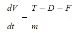
where dV/dt is the acceleration along the runway and m is the mass of the vehicle.
b) tyre design
TYRE DESIGN:
When it comes to safety, tyres are one of the most important components of aircraft. They help to absorb the shock of landing and provide cushioning. It also provides the necessary traction for braking and stopping of an aircraft.
An aircraft tyre is designed to withstand extremely heavy loads while landing, take off, taxing, and parking. The number of wheels required for aircraft increases with the weight of the aircraft, as the weight of the aeroplane needs to be distributed more evenly.
An aircraft tyre is constructed for the purpose it serves.
- They support the weight of an aircraft while it is on the ground.
- It also provides the necessary traction for braking and stopping of an aeroplane.
- Tyre also helps to absorb the shock of landing and provide cushioning the roughness of takeoff, roll-out, and taxi operations.
Unlike an automobile or truck tyre, it does not have to carry a load for a long period of continuous operation. However, an aircraft tyre absorbs the high impact loads of landing, and also it’s operating at high speeds for a short time when required.
Retreading – Retreading is methods of restoring a worn tyre by renewing the tread area or by renewing the tread area plus one or both sidewalls. Repairs are included in the tyre retreading process.
Load Rating – Load rating is the maximum permissible load at a specified inflation pressure.
Ply Rating – Ply Rating is used to identify the maximum recommended load rating and inflation pressure for a specified tyre. It is an index of tyre strength.
Speed Rating – The speed rating is the maximum takeoff speed to which the tyre has been tested.
Skid Depth – Skid depth is the distance between the tread surface and the deepest groove as measured in the mould.
Aircraft tyres must have an approved speed and load rating and have sufficient clearance when retracted through landing gear to allow for tyre growth. Tyre growth is the increase in the size of the tyre due to centrifugal forces at high speed.
Aircraft tyres may be Tube-type or Tubeless
Tubeless tyres are more advantageous over tube-type. There is no longer the use of tube-type tyre in recent aviation. Nowadays all airliners are using tubeless tyres. Tubeless that are meant to be used without a tube has the word TUBELESS on the sidewall of the tyre.
Aircraft tyres may be Radial or Bias
Almost all airliners are using Radial tyre. Bias is an older design, and it’s mainly used for road vehicles. Radial tyres have the word RADIAL on the sidewall. Radial tires are more expensive than bias-ply tyres. Radial tires are in demand because of their lower life cycle cost and long term value.
AIRCRAFT TYRE STANDARD:
Each tyre manufacturer produces their own designs of the tyre with different tread patterns, wear patterns, wear limits etc, and in some cases, different names for the same part of the tyre. But all tyres must meet the approved standards before being accepted by the FAA or CAA.
All commercial aircraft tyres approved under FAA Requirement Technical Standard Order (TSO) C62. A TSO is a minimum performance standard for specified materials, parts, and appliances used on civil aircraft.
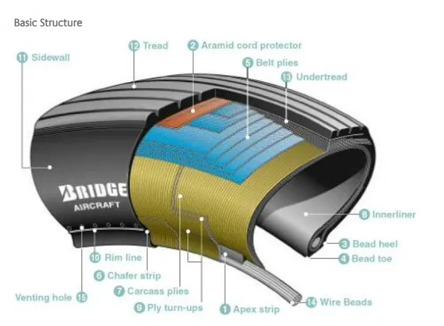
1. Apex strip:
A triangular piece of stiff rubber which is fitted onto the bead core to taper the rigid bead into the flexible body plies in the sidewall.
2. Aramid cord protector:
The tire is constructed with an aramid ply insert between the tread and the top belt to prevent damage to the tire belts.
3. Bead heel:
Outer edge of the bead.
4. Bead toe:
Inner edge of the bead.
5. Belt plies:
Angled belt plies which serve to add strength to the tire especially in the tread area.
6. Chafer strip:
Protective layer of rubber and fabric which prevents chafing between cord body plies and the wheel.
7. Carcass plies:
Layers of rubber-coated fabric plies which have the cords running radially from bead to bead. These provide the tire with strength in the sidewall area.
8. Innerliner:
A sheet of low permeable rubber laminated to the inside of the first casing ply of a tubeless tire to insure retention of air when tire is inflated.
9. Ply turn-ups:
The turned-up ends of plies around the bead. Other plies lock the ends into place.
10. Rim line:
A line provided near the beads to allow inspection of how the tire fits with the rim.
11. Sidewall:
The side area of the tire located between the shoulder and the beads. Composed of rubber, it protects the carcass from damage.
12. Tread:
The functions of the radial tread are the same as those defined for the bias tire.
13. Undertread:
A rubber layer provided for use in retreading the tire and which provides adhesion of tread to the tire carcass. Bridgestone makes this rubber layer thick enough to ensure a high number of retreads.
14. Wire beads:
Two wire bundles (one for each bead) which help to maintain the shape of the tire and anchor it securely to the rim.
15. Venting hole:
The hole through which gas is vented from inside the carcass plies.
* Balance marker
A balance marker, consisting of a red dot, is affixed on the sidewall of the tire immediately above the bead to indicate the lightweight point of the tire.
c) rolling resistance
The friction between aircraft and runway will be proportional to the normal force exerted by the aircraft on the runway.
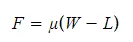
The normal force will be the difference between Weight of aircraft and Lift, the friction coefficient will be typically of a magnitude of 0.02 for a standard tarmac runway.
The rate of change of velocity can be predicted at any point on the take-off roll by substituting results for T, D and F into the initial equation for dV/dt. The subsequent velocity at any point can be found by integrating this resulting equation and the distance traveled found by then integrating the velocity.
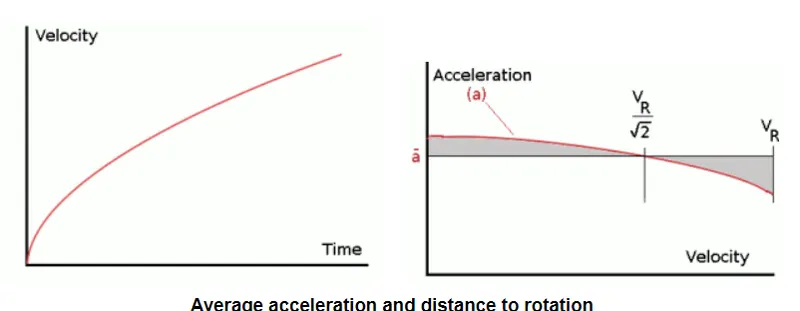
Typically acceleration will be dominated by the drag component as thrust, weight and friction are relatively constant during this period. This leads to the result shown where acceleration is inversely proportional to velocity squared.
Due to the quadratic nature of acceleration change, an average value,
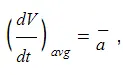
can be used for the take-off run. This average acceleration can be found at the point where,
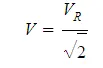
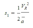
This average acceleration can be used to simplify calculations and the take-off run can be calculated as an equivalent constant acceleration over the complete period of time (tR) taken to get from 0 to VR. For a constant acceleration take-off calculation,
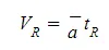
and distance travelled
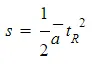
Rearranging leads to a relatively simple calculation to predict distance to rotation point.
d) TYRE PRESSURE:
Aircraft tires generally operate at high pressures, up to 200 psi (14 bar; 1,400 kPa) for airliners, and even higher for business jets
aircraft braking system includes
1)Aircraft disc brakes in the landing gear, used to brake the wheels while touching the ground. These brakes are operated hydraulically or pneumatically. In most modern aircraft they are activated by the top section of the rudder pedals ("toe brakes"). In some older aircraft the bottom section is used instead ("heel brakes"). Levers are used in a few aircraft. Most aircraft are capable of differential braking.
2)Thrust reversers, that allow thrust from the engines to be used to slow the aircraft.
3)Air brakes, dedicated flight control surfaces that work by increasing drag.
4)Large drogue parachutes, used by several former and current military and civilian aircraft
e)brake forces when landing
1)electric brakes
In an electric braking system, electronic control units and electrical wiring replace hydraulic lines and equipment, and electromechanical actuators replace hydraulic pistons. When the pilot steps on the brake pedal, a computer sends information to a control box, which converts these electrical signals into an electromechanical command: the actuators on the brake ring, replacing the hydraulic pistons, press the carbon disks against each other as in a conventional hydraulic system.
2)Spoilers
Spoilers are small, hinged plates on the top portion of wings. Spoilers can be used to slow an aircraft, or to make an aircraft descend, if they are deployed on both wings. Spoilers can also be used to generate a rolling motion for an aircraft, if they are deployed on only one wing.
PARTB)
6A)
1)ROLLING RESISTANCE FORCE:
rolling reistance force is the force which is responsible for resisting the motion of the body like ball, wheel ,tire when the body starts to roll on the surface.

u-rolling resistance coeffcient
m-mass of vehicle and payload in kg
g-acceleration due to gravity.
2)AERODYNAMIC DRAG FORCE:
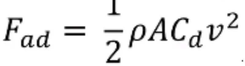
Drag depends on the density of the air, the square of the velocity, the air's viscocity and compressibilty, the size and shape of the body, and the body's inclination to the flow. In general, the dependence on body shape, inclination, air viscosity, and compressibility is very complex.
For drag, this variable is called the drag coefficient, designated "Cd." This allows us to collect all the effects, simple and complex, into a single equation. The drag equation states that drag D is equal to the drag coefficient Cd times the density p times half of the velocity V squared times the reference area A.
the values of drag coefficent cd for various objects are
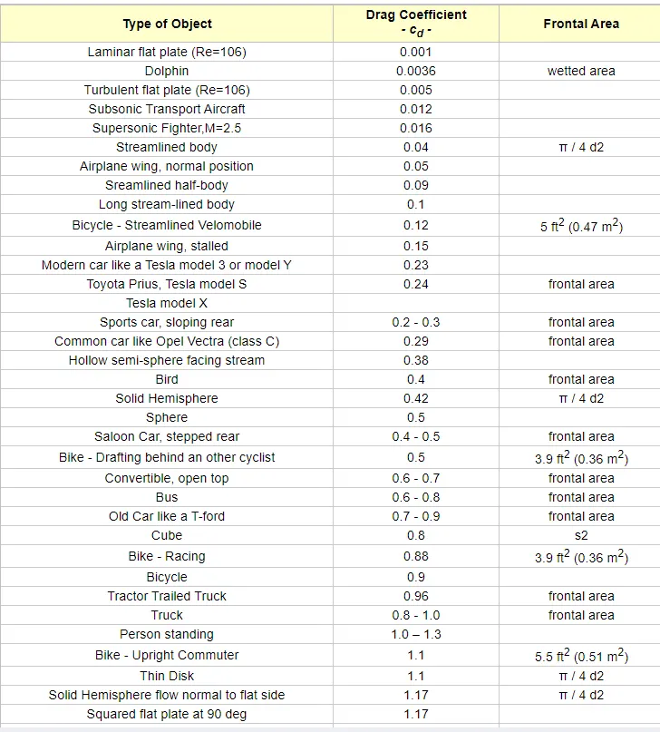
thus for aircraft, let us consider Cda=0.15
CALCULATIONS:
assuming
1)mass of towing vehicle=35000 kg
mass of aircraft which will act as payload for towing vehicle=145000
thus total mass m=35000+145000=180000kg
2)let frontal area of vehicle(A)=18m^2
3)speed of vehicle=25kmph
thus in m/sec- speed of vehicle=25*(5/18)=6.94 m/sec
4)now the rolling resistance coefficient u=0.015
5)air density p=1.225 kg/m^3
let drag coefficient of vehicle Cdv=0.615
and let drag coefficient of air carft Cda=0.15
6) frontal area of vehicle A=18m^2
thus the rolling resistance force

Frr=0.015*180000*9.8=26460 N
thus the aerodyanamic drag force
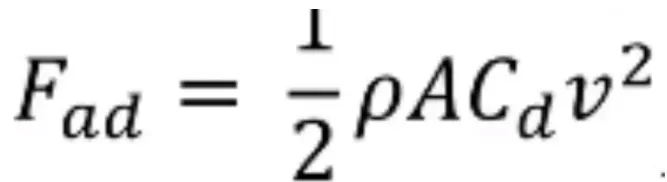
Fad=0.5*1.225*18*(0.615+0.15)*6.94*6.94=406.21 N
the force required to push / pull an aircraft by a towing vehicle =Frr+Fad=26460+406.21=26866.21 N
Thus power required to push / pull an aircraft by a towing vehicle = force* speed =26866.21*6.94=186451 watts
thus power required to push / pull an aircraft by a towing vehicle=186.451 kwatt.
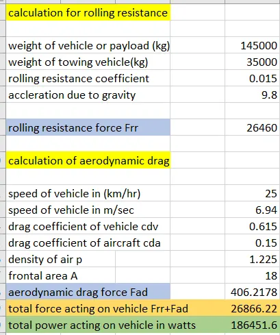
the excel sheet calculator for calculation of force and power required to push / pull an aircraft by a towing vehicle is shown below
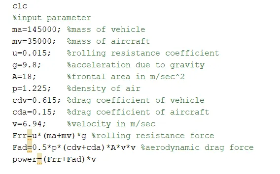
matlab code for finding out force and power required o pull/push the vehicle is
the results displayed on command window are
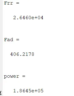
thus the results obtained is same as which are obtained in excel calculator.
6B)
the model for the calculated force and power using Simulink is shown below
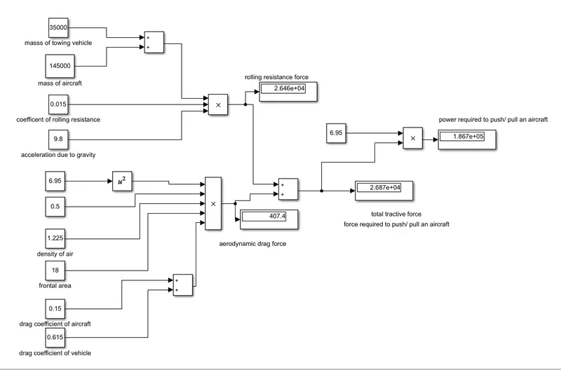
thus got the aerodyamic drag force=407 N
rolling resistance force a=26460N
force required to push / pull an aircraft by a towing vehicle=26870 N
power required to push / pull an aircraft by a towing vehicle=186700 WATTS which is near about same value as got in excel calculator.
now the total power =186.7 kwatts
and let ,motor have efficiency =90 percent
thus near about 250kwatt motor is required
for such high usage, induction motor is used over BLDC motor because of high operating range and cost consideration.
thus Pin=250 kwatt
Pout=186.7 kwatt
now the total mass M=35000+145000=180000 kg
let average taxing time of vehicle is 15 min=900seconds
thu energy=186.7*900=168.03 mega joules
now to calculate duty cycle range
the 250 kwatt motor have a full load current of 420A and full voltage of 400volts
now Pin=Iin*Vin
thus Vin=Pin/Iin
Vin=250/420
now Pout=Vout*Iout
the current at the input and output is same thus we can use
Pout/Pin=Vout/Vin
186.7/250=0.746
thus duty cycle range is from 0% to 74.6%
7)
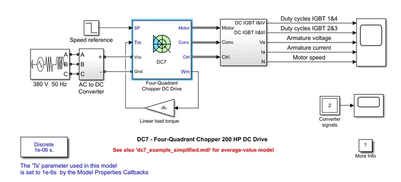
The 200 HP DC motor is separately excited with a constant 150 V DC field voltage source. The armature voltage is provided by an IGBT converter controlled by two PI regulators. The converter is fed by a 515 V DC bus obtained by rectification of a 380 V AC 50 Hz voltage source. In order to limit the DC bus voltage during dynamic braking mode, a braking chopper has been added between the diode rectifier and the DC7block.
The first regulator is a speed regulator, followed by a current regulator. The speed regulator outputs the armature current reference (in p.u.) used by the current controller in order to obtain the electromagnetic torque needed to reach the desired speed. The speed reference change rate follows acceleration and deceleration ramps in order to avoid sudden reference changes that could cause armature over-current and destabilize the system. The current regulator controls the armature current by computing the appropriate duty ratios of the 5 kHz pulses of the four IGBT devices (Pulse Width Modulation). For proper system behaviour, the instantaneous pulse values of IGBT devices 1 and 4 are opposite to those of IGBT devices 2 and 3. This generates the average armature voltage needed to obtain the desired armature current. In order to limit the amplitude of the current oscillations, a smoothing inductance is placed in series with the armature circuit.
CONCLUSIONS:
thus all the objectives are achieved.
REFERENCES:
http://www.aerodynamics4students.com/aircraft-performance/take-off-and-landing.php
https://www.bridgestone.com/products/speciality_tires/aircraft/products/basicstructure/radial.html