Project-1: Powertrain for aircraft in runways
Project: POWERTRAIN FOR AIRCRAFT IN RUNWAYS
Aim Of The Project:
1) Detailed overview of an aircraft and it's parts.
2) Analyzing the behaviour of an aircraft during its motion on the ground and during take-off
3) Modeling and Estimation of the necessary parameters required to control the motion of the aircraft in runways.
Objective:
- To find and list out the total weight of various types of aircrafts.
- To point out the difference in speed of the aircraft w.r.to ground and air.
- To identify the important reason for not to use the aircraft engine power during the motion of the aircraft in the ground of the Airport.
- To find the ways required to move an aircraft in the runway when it is ready to take-off.
- To get a brief idea of the various governing parameters of an aircraft like take off power, tyre design, etc.
- To estimate the various forces required to push/pull an aircraft by a towing vehicle.
- To design the Motor required to fulfill the aircraft towing application in MATLAB Simulink along with the estimation of its power rating and energy requirements. It is also required to estimate the Duty Cycle to control the aircraft speed from zero to highest by making all necessary assumptions.
Solution:
OBJECTIVE I:
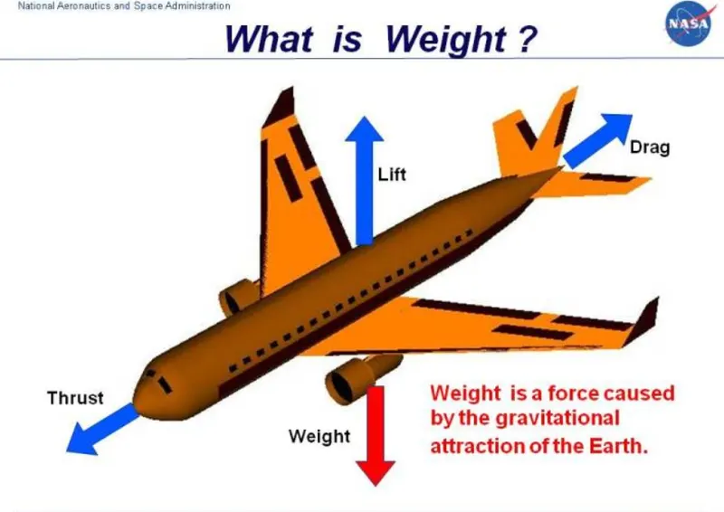
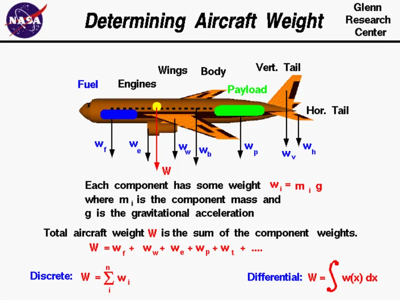
First of all, weight is the force generated by the gravitational attraction of the earth on the airplane. Each part of the aircraft bears a unique weight and mass, and it is very important to know the distribution of these weights over the total aircraft. But for total aircraft maneuvering, we only need to be concerned with the total weight and the location of the centre of gravity. An aircraft is the combination of many parts; the wings, the engines, the fuselage and the tail including the payload and the fuel. Each of the parts mentioned above has a weight associated with it which the engineer can estimate using the formula of Newton's weight equation given by:
`w=m*g`
where, w is the weight, m is the mass and g is the gravitational constants whose value is 32.2 ft/square sec in English units and 9.8 meter/square sec in metric units. The mass of an individual components can be calculated if we know the size of the components and its chemical composition such as material like iron, plastic, aluminium, gasoline, etc. which consists of a unique density. Density(`rho`) is defined as mass(m) divided by the volume(v) given as:
`rho=m/v`
From the above equation we can calculate the mass of the aircraft parts as we can easily find out the density and the volume of the given parts. Therefore, the Total Weight(W) of the aircraft is the sum of the weight of the individual components given as:
W=w(fuselage)+w(payload)+w(engines)+w(wings)+.............
It can be picturised as follows:
After learning the basic definition of the aircraft weight, the Aircraft Flight Manuals(AFM) chalked out the Aircraft authorised Gross Weight Limits(also referred to as Certified Weight Limits) which define the aircraft gross weight as the total aircraft weight at any moment during the flight or ground operation. This authorised weight limits may be equal to or lower than the Structural Design Weight Limits which is defined as weight restrictions or maximum threshold in order to avoid overloading its structure or to avoid unacceptable performance or handling qualities while in operation. The authorised weight limits that can legally be used by an operator or airline are those listed in the AFM and the weight and balance manual. The authorised weight limits are choosen by the airline and they are referred to as 'purchased weights'.
An operator may purchase a certified weight below the maximum design weights because many of the airport operating fees are based on the aircraft AFM maximum allowable weight values. Maximum weights established for each aircraft by design and certification must not be exceeded during aircraft operation(ramp or taxying, takeoff, en-route flight, approach and landing) and during aircraft loading(zero fuel conditions, centre of gravity position and weight distribution).Weights can be restricted in some type of aircrafts depending on the aircraft handling requirements such as for example, aerobatic aircraft, where certain aerobatic manoeuvres can only be executed with a limited gross weight. The classification of the different types of weights under gross weight can be made in the following categories:
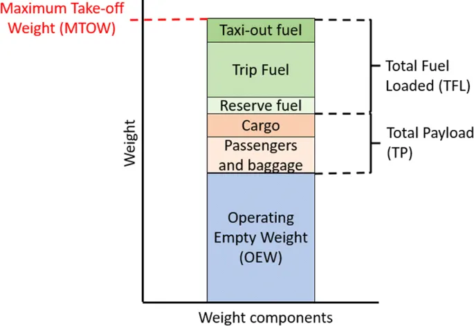
- Maxumum Ramp Weight(MRW): Also known as Maximum Taxi Weight(MTW) is the maximum weight authorised for taxiing or towing an aircraft on the ground as limited by aircraft strength or airworthiness requirements. The difference between the maximum taxi/ramp weight and the maximum take-off weight depends on the size of the aircraft, the number of engines, APU operation, and engines/APU fule consumption, which is typically assumed for 10-15 mins allowance of taxi and run-up operations.
- Maximum Take-Off Weight(MTOW): The maximum takeoff weight is the maximum certificated design weight for takeoff run as limited by aircraft strength and airworthiness requirements. The maximum takeoff weight is always less than the maximum taxi/ramp weight to allow for fuel burned during taxi by the engines and the APU.
- Maximum Landing Weight(MLW): The Maximum Landing Weight is the maximum design certified weight for normal landing of the aircraft. It generally depends on the landing gear strength or the landing impact loads on certain parts of the wing structure given by the relation as:

- Maximum Zero Fuel Weight(MZFW): The maximum zero fuel weight is the maximum certified weight of the aircraft less all usable fuel and other specified usable agents as limited by aircraft strength and airwothiness requirements. It is the maximum weight permitted before usable fuel and other specified usable fluids are loaded in the specified section of the aircraft. The weight difference between the MTOW and the MZFW may be utilised only for the addition of the fuel.

where OEW stands for Operational Empty Weight.
- Minumum Flight Weight(MFW): Minimum Certified weight for flights as limited by aircraft strength and airworthiness requirements.
- Operational Empty Weight(OEW): The Manufacturer's Empty Weight(MEW) and the operator's item are summed up to the Operational Empty Weight(OEW). The OEW is fixed for a specific aircraft and only gets changed during maintenance and operational changes. OEW is the empty weight that is used in the flight simulator or the usual planning software.

- Actual Zero Fuel Weight(AZFW): If we add the Payload to the Empty Plane Weight then we get the Actual Zero Fuel Weight. Basically the Payload includes the passenger weight, the passenger luggage weight and the cargo weight given by the following relationship:

Therefore the Summary of the Operational Weight is picturised as follows:
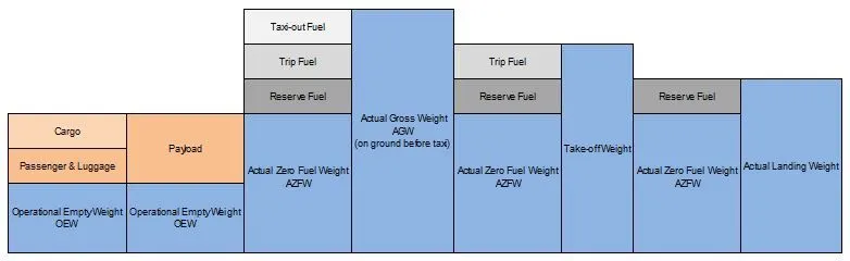
For example let us take an aircraft of an AIRBUS A319, where the division of the weight is shown as follows:
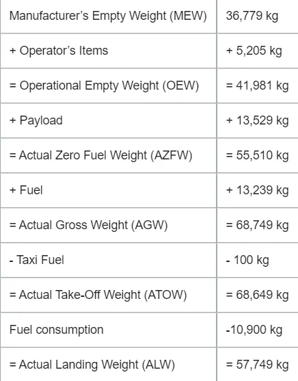
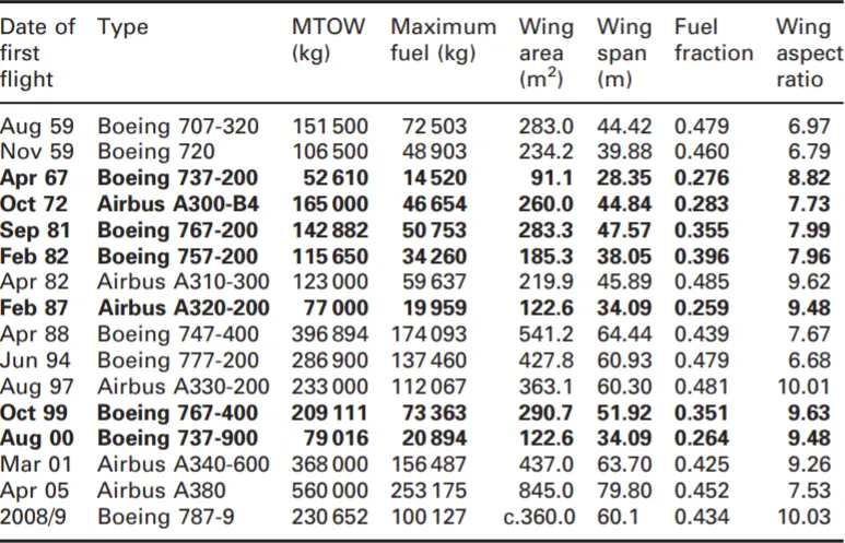
After getting a brief idea about the classification of the operational weight of an aircraft. The weight of the various aircrafts w.r.to the Maximum Take Off Weight is given as a chart in the following diagram:
OBJECTIVE II:
To understand the ground speed or the air speed it is necessary to define the relative velocity so as to pick a pick a fixed reference point and measure the velocities relative to the fixed point. Let us discuss the two speed as mentioned above in order to understand the relationship between them:
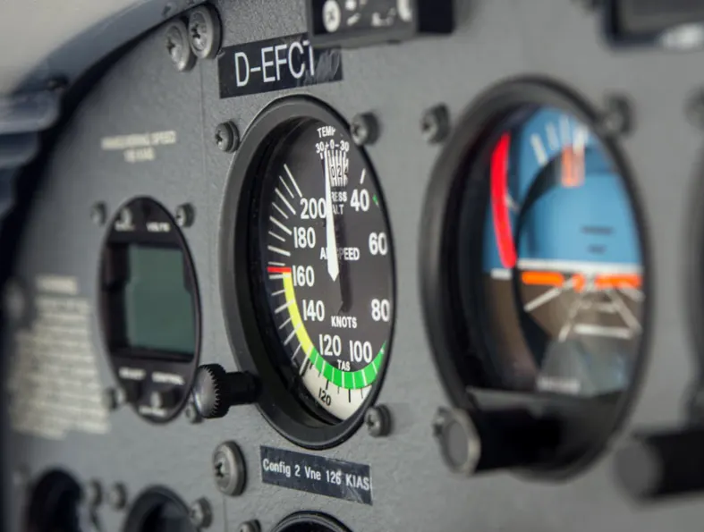
- Indicated AirSpeed(IAS): This is the airspeed based upon the ratio of stagnation and the static ambient air pressure where the plane is flying.The Speed limits of the sky, like not exceeding 250 knots below 10,000 feet MSL are all written as the indicated air speed values as shown below:
- Calibrated AirSpeed(CAS): This Airspeed indication is corrected for installation and equipment error. It reflects a more precise airspeed at STP based on the installation. At certain air speed with certain flap settings, the installation and the instrument errors may total several knots which can be more at low airspeeds with nose high pitch attitudes. Calibrated air speed is same as the True Airspeed and if there is no wind then it is also same as the ground speed.
- True Airspeed(TAS): It is the indicated airspeed corrected for nonstandard pressure and the temperature. It reflects the actual speed of the relative airflow over the aircraft. In still air the TAS is equal to the ground speed. Pressure decreases with higher altitudes, so for any given true air speed, as you climb, fewer and fewer air molecules will enter the pilot tube and because of that indiacted air speed will always be less than the true air speed.
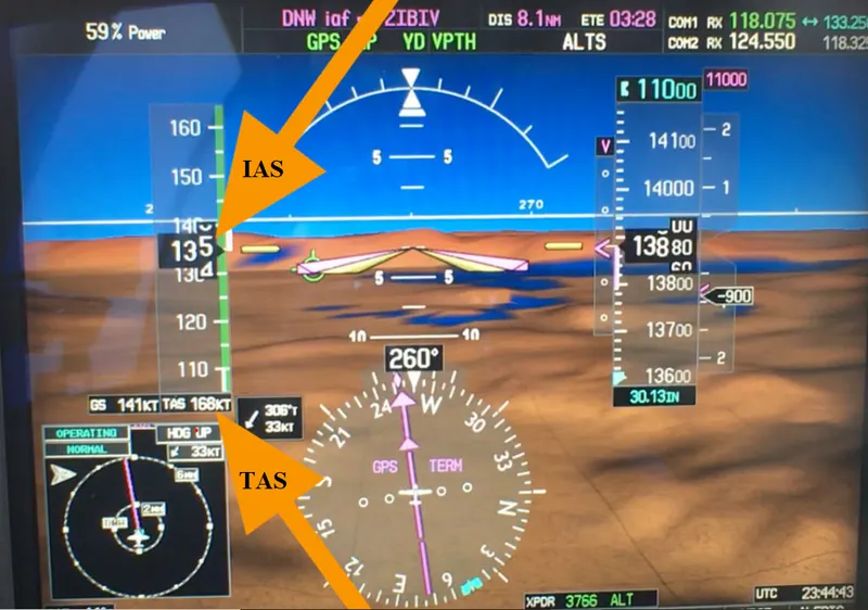
- Ground Speed(GS): It is the speed the aircraft is crossing over the ground at. It will be equal to the sum of the true air speed of the aircraft and the headwind component of the wind aloft at the altitude the airplane is flying at.
The air speed and the ground speed together can be visualise as follows:
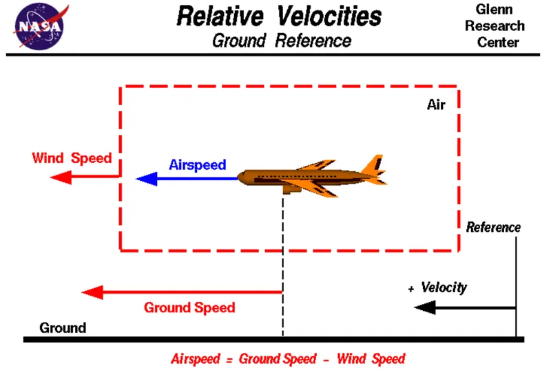
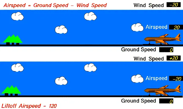
It becomes important to differentiate and understand the terms very well as they will play an integral role in your distance and fuel calculations in order to know whether you can safely complete a flight. On one hand, Airspeed is critical for the pilots because it what the plane 'feels' when its flying. Too little airspeed and the wings won't generate enough lift to fly and too much can able to damage the plane and on the other hand, Ground Speed is how quickly you are getting when you are going which is also important because the engine consumes a certain amount of fuel per hour. So if an airpalne has a ground speed of 100 knots then it will fly 100nm per hour relative to the ground. This speed is influenced by the head and the tailwind ; the ground speed will be higher than the air speed if the aircraft experienced tailwind and vice versa.
The animated visualisation of the two speeds during take-off is shown in the figure below:
OBJECTIVE III:
The problem that most aircraft face is during the parking condition where in order to get to the runway, we need to move backward off the stand first. Unfortunately, aircraft can't able to just move backward as they don't have a reverse gear technology. Sometimes, in order to do the above function we use the assistance of the pushback tug where the weight of the tug is utilised to ensure that the wheels doesn't just spin on the tarmac. However with bigger aircraft tug designers run into a problem, as they will unable to provide the enough thrust to keep them running. So sometimes when the tug get disconnected the engines are allowed to run for a while but the risks which may arise from engine ground running relate to the potential for loss of control of the aircraft by those persons occupying the pilot seats in the flight deck. Unwanted consequences from such static running are mainly related to those arising from the unintended movement of the aircraft during engine running effectively a loss of control- especially during high power engine running. Damage can occur to the aircraft itself, other aircraft nearby or to airside structures. In addition, there is a risk of injury to the ground support personnel who may be in relatively close proximity to the aircraft.
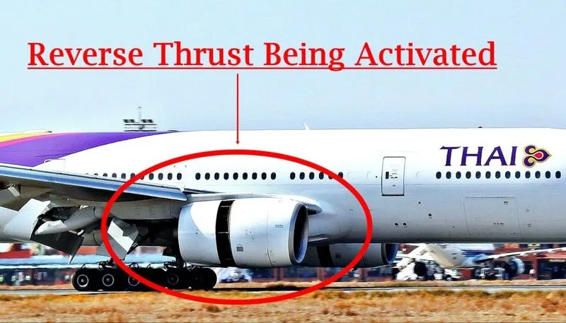
Another type of danger poses by running the engine on the airport is given as follows:
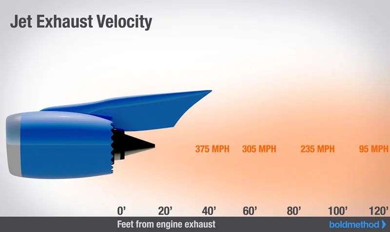
- During taxiing or towing, if engines are applied it will operate at rated thrust levels by which the exhaust wake can exceed 375mi/hr(325knots or 603kmph) immediately aft of the engine exhaust nozzle, this phenomenon is also known as Jet Blast. This exhaust flow fields extends aft in a rapidly expanding cone, however an airflow of 300mi/hr(260knots or 483kmph) can still be present at the empennage which can leads to significant hazard to the people or the environment that can persist for hundreds of feet beyond this area.
OBJECTIVE IV:
The first phase of flight, after all doors have been secured, involves the movement of the aircraft away from the terminal jetway and along taxiways to the runway. A motorized vehicle called a tug sometimes is used to push the aircraft back from its gate. At some airports, certain aircrafts are permitted to power back. This means that following engine starts at the gate, the thrust reversers are used to literally back the aircraft away from the gate. The aircraft then moves under its own powers along the taxiways. Since aircrafts are designed primarily for flights and are not ground vehicles they are taxied at a very low speeds. When ready for take-off, and cleared by Air-Traffic Controller(ATC) to proceed, the pilot or the first officer of an aircraft releases the brakes and advances the throttle to increase the engine power so as to accelerate down the runway. All the flight phases can be categorised as the picture given below:
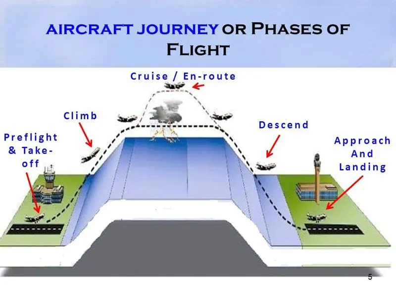
There are certain factors that is needed to be kept in mind before the aircraft is ready to take-off, it must go through various praparatory pre-takeoff procedures. Among the things that happen to a plane before its boarded and ready to take-off includes:
- Restocking the plane with food and necessary items for its next flight.
- Cleaning the plane for make it ready for the next flight; this can be quick cleaning job if the plane is doing several flights back to back, or a more thorough one once its itinerary is completed.
- Check of onboard systems to see if there is anything that needs to be repaired or monitor.
- Refueling
- Pushback and getting the plane in position for its next flight.
- Pre-flight checks, boarding and asking for clearence for take-off.
OBJECTIVE V:
Take-Off Power:
For Light aircraft usually full power is used during tale-off. Large transport aircraft like airliner may use a reduced power for takeoff, where less than full power is applied in order to prolong the engine life, reduce maintenance cost and ruce noise emissions. In some emergency cases, the power used can then be increased to increase the aircraft's performance. Before takeoff, the engines, particularly piston engines are routinely run up at high power to check for engine related problems. The aircraft is permitted to accelerate to rotation speed(often referred to as Vr). The nose is raised to a nominal 5-15 deg nose up pitch attitude to increase lift from the wings and effect lift off. For most aircraft, attempting a takeoff without a pitch-up would require cruise speeds while still on the runway.
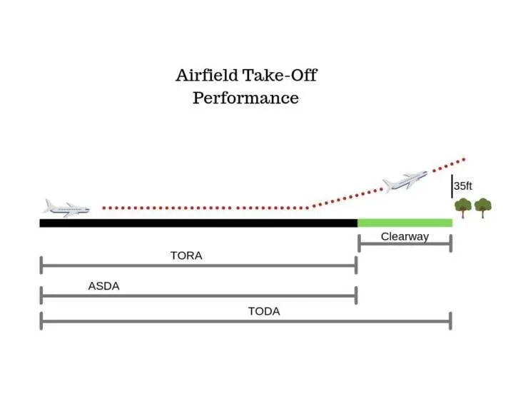
The take-off power is controlled in such a fashion that it can cover the 35 feet screen height plays in the takeoff. We need to look at the various distances that affect the take-off performance of an aircraft, which are as follows:
- TAKEOFF RUN AVAILABLE(TORA): It is the distance from the point at which the aircraft can start its takeoff run to the point at which the surfrace can no longer bear its weight.
- THE CLEARWAY: This is the area at the end of the TORA that is free from any obstructions exceeding 0.9 meters in height like buildings or trees. The aircraft can use this area to acheive the 35 feet screen height.
- TAKEOFF DISTANCE AVAILABLE(TODA): The TODA is the total distance that the aircraft has to start its takeoff run and climb to the 35 feet screen height. On a runway without a clearway, The TODA will be equal to the TORA.
- ACCELERATE-STOP DISTANCE AVAILABLE(ASDA): The final distance that must be considered for takeoff performance is the ASDA. This is the distance of weight bearing surface available to the aircraft to accelerate and then come to a safe stop in the case of a rejected takeoff.
The complete visualisation is shown in the figure below:
Tire Design:
Carcass piles are used to form the tire. They are sometimes called casing piles. An aircraft tyre is constructed for the purpose its serves:
- They support the weight of an aircraft while it is on the ground.
- It also provide the necessary traction for braking and stopping of an aeroplane.
- Tyre also helps to absorb the shock of landing and provide cushioning the roughness of takeoff, roll-out and taxi operations.
Unlike an automobile or truck tyres, it does not have to carry a load for a long period of continuous operations. However, an aircraft tyre absorbs the high impact loads of landing and also its operated at high speed for a short period of time when required.
TIRE CONSTRUCTION:
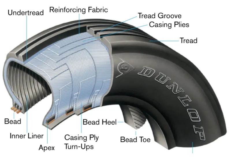
The aircraft tire construction consists of the following components:
1. Tread: The tread is a special rubber compound which is resistant to abrasive wear, cutting, chunking, and heat. Around its circumference the tread has moulded grooves which help to remove water between the tread and the runway during wet conditions and increase the traction and the grip.
2.Inter-Tread Fabric:
- An aircraft tyre can include Inter-Tread fabric(ITF) also known as tread reinforcement layers. This is one or more layers of nylon fabric between the casing piles and the base of the tread. The ITF keeps the tread stable and free from distortion during high speeds when there is increased centrifugal force. The ITF also gives protection to the casing piles if debric cuts the tread.
- For special high speed applications, the ITF can be moulded into the rubber of tread. As the tyre wears, the ITF is seen in the tread pattern.
3.Casing:
- The primary strength of the tyres is in the casing piles. A casing pile is a layer of high modulus cord which is coated with rubber compound to make a fabric. This fabric is assembeld in layers.
- For bias(cross-ply) aircraft tyres, the casing piles are installed around the bead coils to amke the sidewalls of the tyres. This gives the bias tyre its strength. Adjacent layers of casing ply are put at opposite bias angles. The dstrength and load capacity of the tyre is related to the number of piles and bias angles.
- In a tyre for a millitary applications, the casing cord could be a red colour for easy visibility and indication of wear.
4.Breakers: A breaker is an added layer of fabric that gives more strength. The breaker layers are laid directly on the top ply across the width of the tread. They are a part of the tyre casing, and are not removed when the tyre is retreaded.
5.Beads:
- The tyre beads hold the tyre on its wheel. The beads are made up of high tensile wire strands. Each wire strand is coated with rubber compound and is wound into a coil of specified diameter for the tyre. A rubber component known as the apex is applied to the top of the bead coil to make bead assembly.
- The bead filler is a fabric component which helps to hold the bead coil assembly together. The bead filler also gives more strength to the bead assembly and more stiffness to the area of the tyre that is compressed with a high load against the wheel rim.
6.Chafers:
- A chafer components prevents chafing damage when the tyre is against the rim. It also decreases the conduction of brake heat to the tyre from the rim.
- The chafer component is a strong nylon material which is coated with rubber. The chafer assembly is attached to the first ply and pulled around the bead face to the clinch area.
7.Sidewall: The sidewall is a layer of special rubber formulated with anti-oxidants. This rubber layer provides protection against weathering to the casing piles and is resistant to contamination, cuts and flexing.
8.Inner Liner: The inner liner is a layer of special rubber compound around the inner face of the tubeless tyre. The inner liner is attached to the first casing ply and is a seal to prevent leakage inflation gas and moisture into the tyre casing.
9.Chined Tyres: Some types of nose wheel tyres include one(or two) chines moulded into the rubber at one of the shoulder buttresses. A chine is a rubber extension, (arounf the tyre circumference), that deflects water from rear fuselage mounted engines during aircraft movement on a wet runway.
10.Breaker Package(Belt Piles): The belt piles is a number of piles made up of nylon or aramid attached below the tread of a radial-ply tyre. The breaker package give stiffness to the tread area and helps to keep the circumference constant as the tyres expand when it is inflated.
The aircraft tyre(bias type which is most common) cross-section is shwon on the picture below:
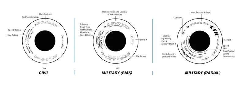
The Classification of the tyres w.r.to sidewall markings are shown in the figure below:
Rolling Resistance:
Tire rolling resistance is the energy that your vehicle needs to send to your tyres to maintain movement at a constant speed over the surface. In other words, it is the effort required to keep a tyre rolling. It is mainly caused by non-elastic effects; i.e not all the energy needed for deformation (or movement) of the wheel, roadbed, etc. is recovered when the pressure is removed. The main contributor to the Rolling Resistance is the process known as Hysteresis. Hysteresis is essentially the energy loss that occurs as a tire rolls through its footprint. The energy loss must be overcome by the vehicle's engine which results in wasted fuel.
The Rolling Resistance can be expressed by the generic equation:
Fr=`cunderset(rr)`*`m*g`
where; `cunderset(rr)`is the rolling resistance coeficient(dimensionless)
m is the mass of the body(kg or lb)
g is the acceleration of gravity(9.8m/sec2 or 32.174ft/sec2)
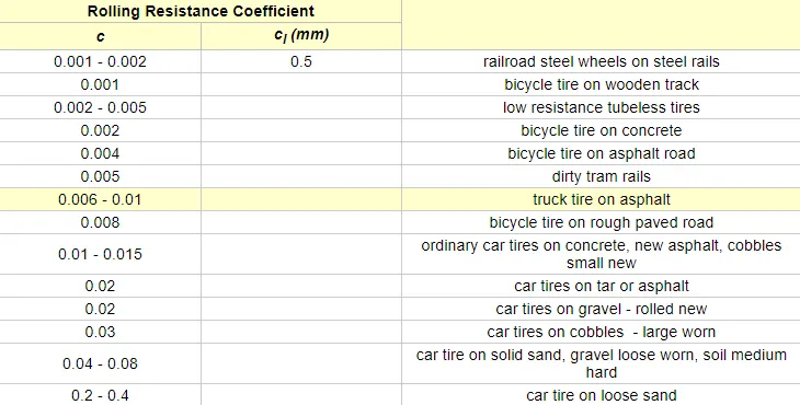
The Rolling Resistance Coefficient is greatly get influenced by the factors like wheel design, rolling surface, wheel dimensions, etc.
Some typical values of rolling resistance coefficient(`cunderset(rr)`)for different vehicles is shown in the figure given below:
Tyre Pressure:
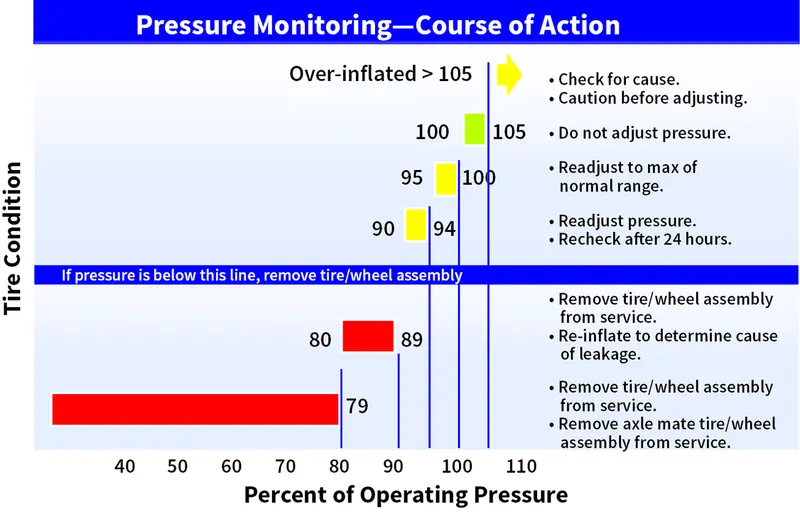
The aircraft tires are properly inflated which is a crucial criteria for pre-flight and routine service checks which can go a long way to maximizing tire utilization and minimizing risks to safe operations. There is a significant difference between the passenger car/truck tires and the aircaft tires w.r.to rated inflation pressure, load and the speed. The passenger car and truck tires can able to operate continuously because they reach thermal equlibrium while aircraft tires do not. An aircraft tire which taxis continuously at rated load and 40mph will continue to heat up until the tire fails. The failure to reach thermal equilibrium is a consequence of the high deflections(the difference between the unloaded and loaded tire section height) at which aircraft tires operate. High inflation pressure and high deflection rates -2.5 times greater than a car tire allow relatively small tires to supprot the high load of an aircraft.
The operating conditions of the tire w.r.to the tire pressure is shown in the figure below:
Brake Forces when Landing:
The brakes used in the aircraft while landing are as follows:
- Aircraft Disc Brakes: It is used to brake the wheels while touching the ground. These brakes are operated hydraulically or pneumatically. In most modern aircraft they are activated by the top section of the rudder pedals(toe brakes). In some older aircraft the bottom section is used instaed(heel brakes). Levers are used in a few aircraft. Most aircraft are capable of differential braking.
- Thrust Reversers: It is used on a jet aircraft to provide a significant way of increasing the rate of deacceleration during the initial stages of both a landing roll or a rejected takeoff from a high speed. Use of reverse thrust on low wing aircraft with mounted engines should be limited to the time when the aircraft is on an active runway.
- Air Brakes: Air brakes or speed brakes are used to cause the aircraft to slow more rapidly when they were deployed. They produce a drag which required a high power setting, these settings are much more responsive and rapid thus making power and glide slope corrections on approach more rapidly with speed brakes deployed.
- Large Drogue Parachutes: It is a parachute designed for deployment from a rapidly moving object. It is used for various purposes such as to decrease the speed, to provide control and stability, or as a pilot parachute to deploy a larger parachute.
OBJECTIVE VI:
The forces required to push/pull an aircraft by a towing vehicle are given as follows:
- Rolling Resistance Force: As discussed earlier, it is the force which is responsible for resisting the motion of the body such as ball, tire or wheel, when its starts to roll on the surface. The governing equation of this force is given by:
`Funderset(rr)`= `Cunderset(rr)`*m*g.
where, `Cunderset(rr)`- Rolling Resistance Co-efficient(dimensionless)
m - mass of the body under consideration
g - acceleration due to gravity.
- Aerodynamic Drag Force: Drag is the aerodynamic force which opposes the motion of the body. It is actually the resistance offered by the air to the movement of the body. So when a car is moving it is actually displaces the air which in turn affects the car's speed and its performance. Manufacturers always try to keep the Aerodynamic Drag to the minimum possible value. It is due to the fact that this force has a negative impact on the vehicle's performance and the efficiency. The upright stance of some vehicles gives it a drag co-efficient of 1.30 while a randrop design has the least amount of drag. The governing equation of these force is given as follows:
`Fundersetd`= `Cundersetd`*`(rho*v^2*A)/2`
where, A - It is the reference area(frontal area of the car)
v - It is the velocity/flow velocity relative to the object(speed of the car)
`rho` - Air Density
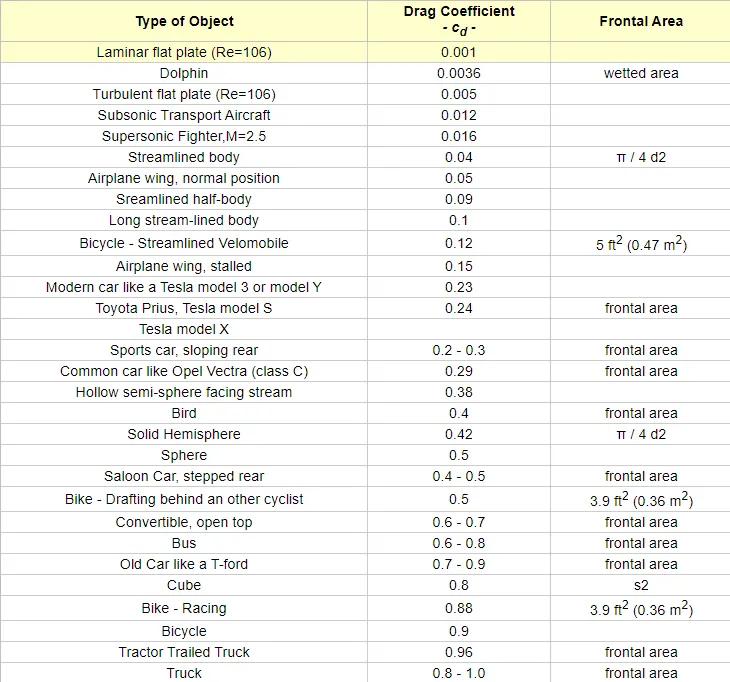
`Cundersetd`- It is the Drag Coefficient which is dimensionless related to the object's geometry and take into account both skin friction and form drag.
The Drag Co-efficient for various objects is shown below:
Calculation:
Assumption:
Towing Vehicle Mass(kg)-40000
Mass of the aircraft which act as a payload to the Towing Vehicle(kg)- 150000
Therefore, Total Mass of the towing vehicle(m)=150000+40000=190000kg.
Frontal Area of the vehicle(A)=18`m^2`
Speed of the vehicle(v)= 20kmph.
In m/sec;
Speed of the vehicle(v) = 20*5/18=5.556m/sec
Rolling Resistance Co-efficient(`Cunderset(rr)`)=0.01
Now, Rolling Resistance Force(`Funderset(rr)`)=`Cunderset(rr)*m*g`
=0.01*190000*9.8
= 18,620N.
Similarly,for Aerodynamic Drag:
Coefficient of Drag for the towing vehicle(`Cunderset(d)`_v)=0.608
Coefficient of Drag for the aircraft(`Cundersetd`_a)=0.15
Air Density(`rho`)=1.225kg/m3
Now, Aerodynamic Drag(`Funderset(ad)`) = 0.5*(`Cundersetd`_v + `Cundersetd`_a)*`v^2`*`rho`*A
= 0.5*(0.608+0.15)*`5.556^2`*1.225*18
= 257.97N
Therefore, Total Force Required to Push/Pull the aircraft by the Towing Vehicle is:
= `Funderset(rr)`+ `Funderset(ad)`
= 18,620+257.97
= 18,859.97N
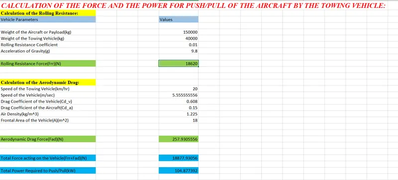
The Excel Sheet Calculation of both the Force and the Power is shown below:
OBJECTIVE VII:
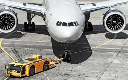 Figure shows the Towing Vehicle Application
a) Assumption for the Design of the Electric Powertrain for aircraft towing application is given below:
Mass of the Aircraft(kg) - 150000
Mass of the Towing Vehicle(kg) - 40000
Rolling Resistance Co-efficient(`Cunderset(rr)`) - 0.01
Air Density(`rho`)(kg/m^3) - 1.225
Drag Co-efficient of the vehicle(`Cundersetd`_v) - 0.608
Drag Co-efficient of the Aircraft(`Cundersetd`_a) - 0.15
Frontal Area(A)(m^2) - 18
Tyre Pressure - 196PSI/13.51Bar
Speed of the Towing Vehicle(v) - 20kmph/5.556mpsec
Towing Time - 2min
Radius of the Wheel of the Vehicle(R) - 0.4m
Now from the excel calculation we get the Total Force acting on the Vehicle as:
Total Traction Force(F) - 18877.93056N
and the Corresponding Power Required (P) - 104.877392kW
Now, The Torque required by the vehicle to move is given by:
Torque(T) - Force(F)*Radius of the Wheel(R)
Therefore, T = 18877.93056*0.4
= 7551.1722Nm
The Energy required by the vehicle for Towing application is given by:
Energy(E) = Power(P)*Towing Time
= 104.877392*2/60
= 3.496kWh
For this application an electric motor which can be either a BLDC motor or an Induction Motor is choosen for the above power specs is given below:
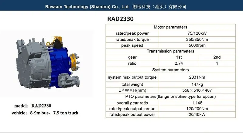
Here in the above figure, the Peak Motor Output Power given in the Motor Parameters in the input to the Towing Vehicle:
So therefore, Input Power to the Towing Vehicle(kW) - 120
Output Power of the Towing Vehicle(kw) - 104.877392
`:.`, Duty Cycle = `(Output Power)/(Input Power)`;
= 104.877392/120
= 0.87
In percentage; it will be 87%
So we can say that to control the Aircraft Speed from Zero to Highest the Duty Cycle Range will be from 0 to 0.87 respectively.
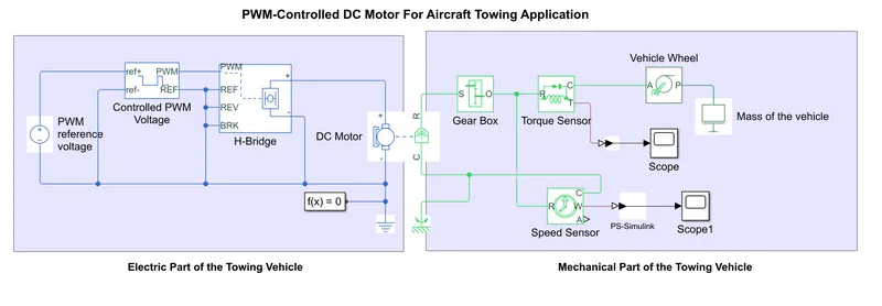
b) The following Towing Application for the Aircraft is represented in the MATLAB Simulink using DC Motor for simplification is shown below:
The Corresponding Torque Results is shown below:
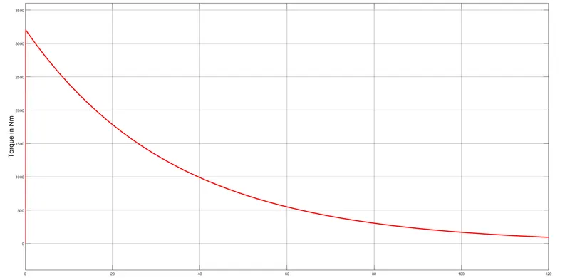
The Corresponding Speed Results:
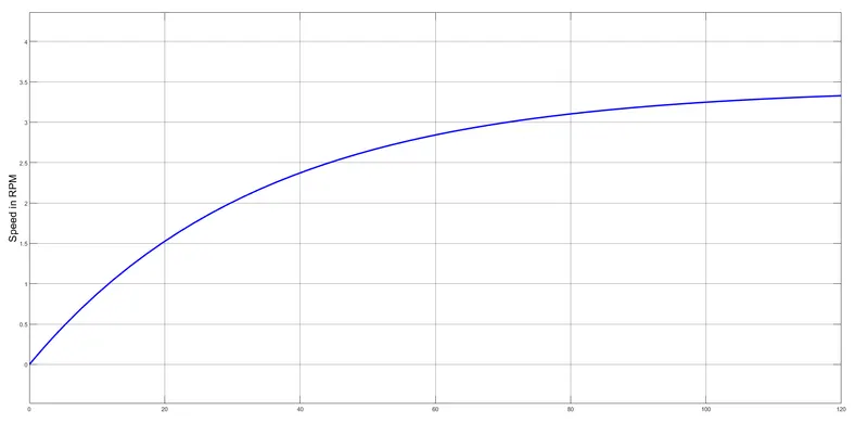
From the above two results it is clearly visible that as the Speed of the Towing Vehicle is increasing then correspondingly the Torque is decreasing from its maximum value.
c) The Power Train Block Diagram for the entire Towing application starting from the Aircraft to the Towing Vehicle is given below:
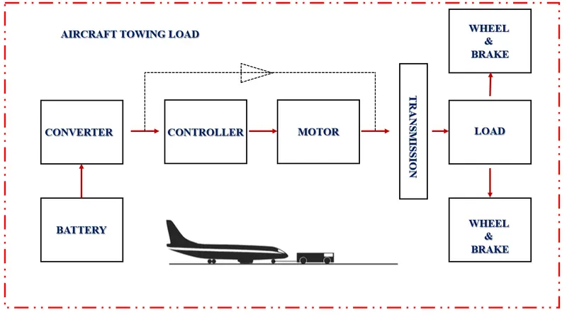
From the diagram we can see that the Battery is supplying the power to the Motorand that is controlled by the Controller unit which is nothing but the Inverter Circuitry. As automotive batteries generally operates on DC while the grid operates on AC, so a converter is needed to transfer power to the battery. Because of these capability of EV vehicle, the efficiency of them are much more(80-60%) than the conventional IC engine type of vehicle(25-30%). This motor is then responsible for controlling the wheels and the brakes through the Transmission and the Gear System.
References:
- https://en.wikipedia.org/wiki/Aircraft_gross_weight
- https://www.grc.nasa.gov/www/k-12/airplane/weight1.html
- https://www.grc.nasa.gov/www/k-12/airplane/weight2.html
- https://mediawiki.ivao.aero/index.php?title=Standard_aircraft_weight
- https://www.boldmethod.com/blog/lists/2019/11/the-four-types-of-airspeed-and-how-each-works/
- https://aviation.stackexchange.com/questions/37089/why-do-we-need-to-know-both-groundspeed-and-airspeed
- https://www.skybrary.aero/index.php/Aircraft_Ground_Running
- https://thepointsguy.com/guide/how-pilots-move-a-plane-around-on-the-ground/
- https://www.dunlopaircrafttyres.co.uk/media/1219/dunlop_dm1172_rev8_nov_2019.pdf
- https://www.aviationpros.com/engines-components/aircraft-airframe-accessories/article/12029645/how-does-tire-pressure-maintenance-impact-aircraft-safety
- https://www.engineeringtoolbox.com/drag-coefficient-d_627.html
- https://www.bridgestonetire.com/tread-and-trend/tire-talk/tire-rolling-resistance
- https://en.wikipedia.org/wiki/List_of_aircraft_braking_systems
- https://aip.scitation.org/doi/pdf/10.1063/1.5091917
- https://engineering.purdue.edu/~propulsi/propulsion/jets/basics/reverse.html
- https://asrs.arc.nasa.gov/publications/directline/dl6_blast.htm