Project-1: Modelling an electric Car with Li-ion battery
Q. Create a MATLAB model of electric car which uses lithium ion battery and suitable motor. Choose suitable blocks from Simscape or Powertrain block set. Implement the vehicle speed control using PI controller and generate brake and accelerator commands. Avoid using readymade driver block for speed control.
Prepare a report about your model including following:
Objectives, System level configurations, Model parameters, Results, Conclusion.
(Note- The simulink model file should be compulsorily attached)
Objective :
To create a MATLAB model of electric car which uses lithium ion battery and suitable motor.
- Choose suitable blocks from Simscape or Powertrain block set.
- Implement the vehicle speed control using PI controller and generate brake and accelerator commands.
- Avoid using readymade driver block for speed control.
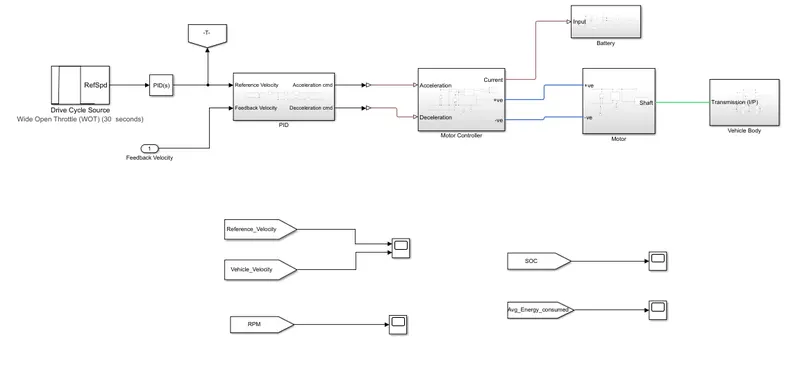
Simulink Model :
PID :
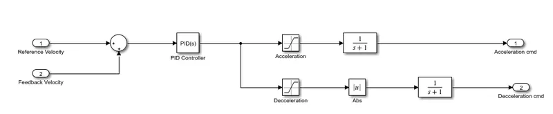
Subsystem :
Blocks Used :
Acceleration :

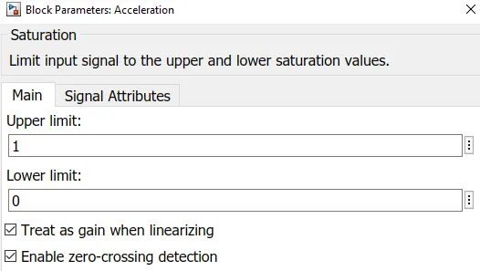
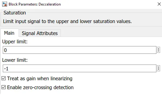
Decceleration :

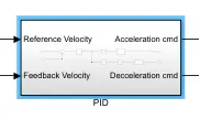
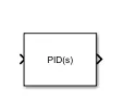
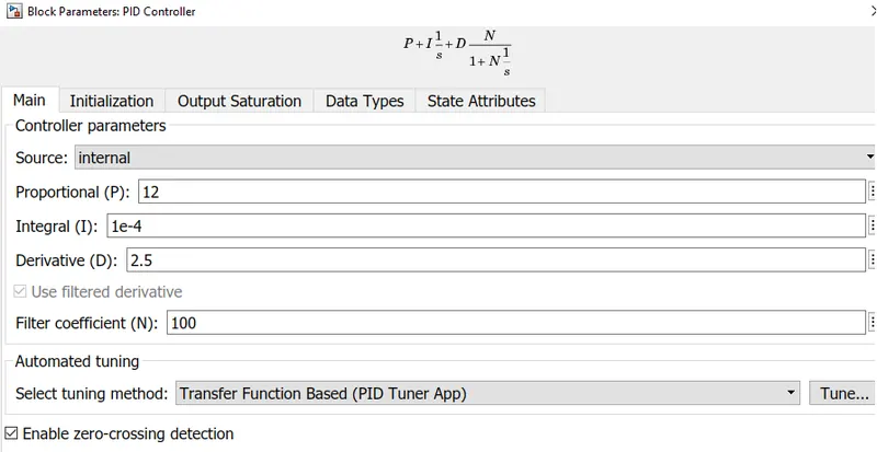
PID Block :
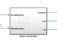
Motor Controller :
Subsystem :
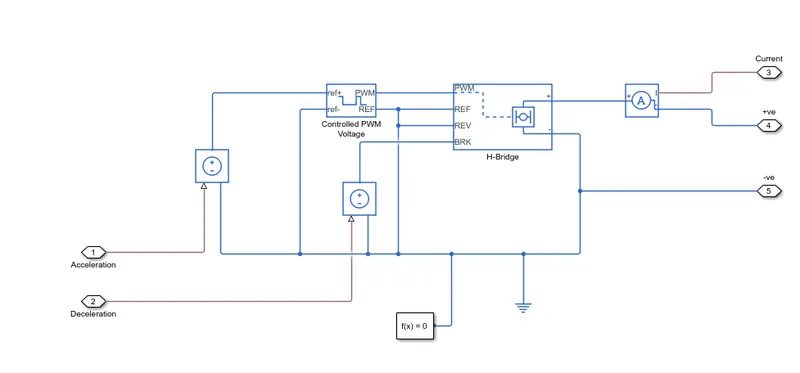
Blocks Used :
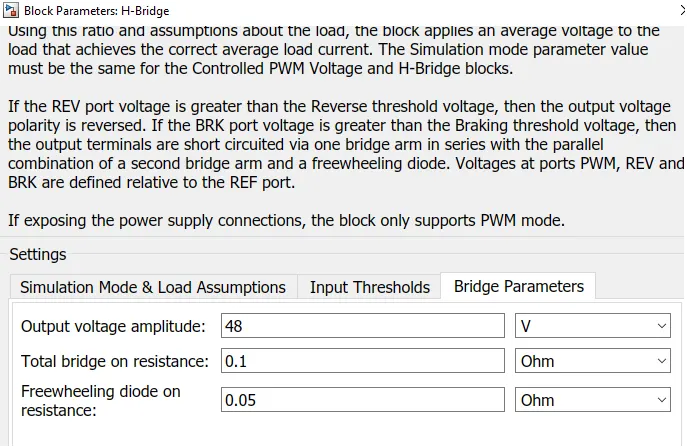
H-Bridge :
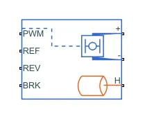
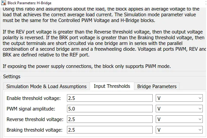
- This block represents an H-bridge motor drive. The block can be driven by the Controlled PWM Voltage block in PWM or Averaged mode. In PWM mode, the motor is powered if the PWM port voltage is above the Enable threshold voltage.
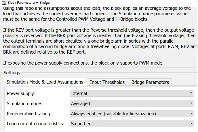
- In Averaged mode, the PWM port voltage divided by the PWM signal amplitude parameter defines the ratio of the on-time to the PWM period. Using this ratio and assumptions about the load, the block applies an average voltage to the load that achieves the correct average load current.
- The Simulation mode parameter value must be the same for the Controlled PWM Voltage and HBridge blocks.
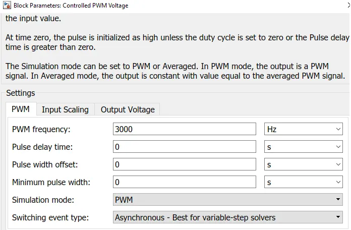
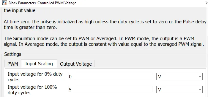
Controlled PWM Voltage :
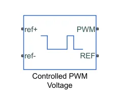
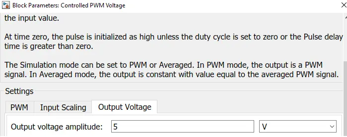
- This block creates a Pulse-Width Modulated (PWM) voltage across the PWM and REF ports. The output voltage is zero when the pulse is low, and is equal to the Output voltage amplitude parameter when high.
- Duty cycle is set by the input value. Right-click the block and select Simscape->Block choices to switch between electrical +ref/-ref ports and PS input u to specify the input value.
Solver Configuration :

Defines solver settings to use for simulation.
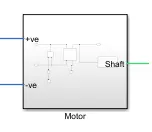
Motor :
Subsystem :
Blocks Used :
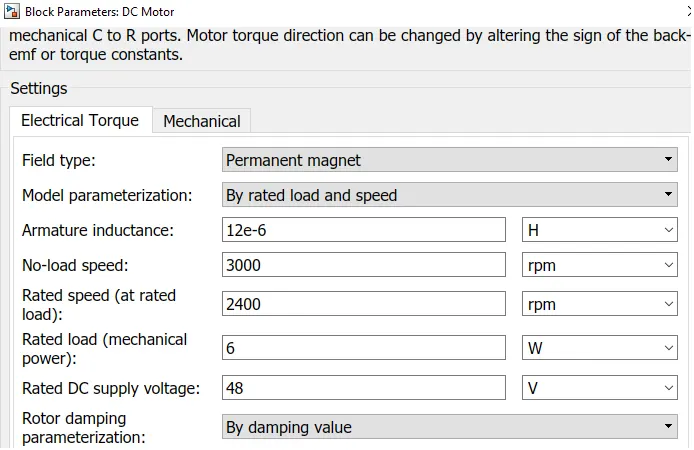
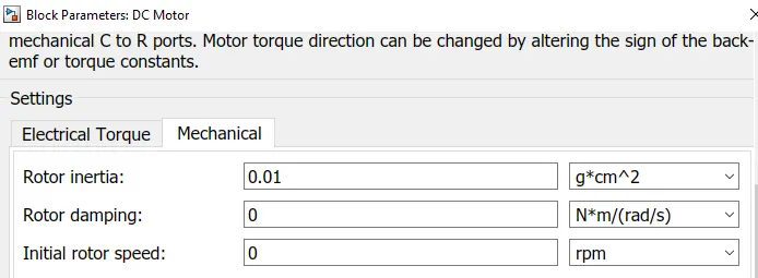
DC Motor :
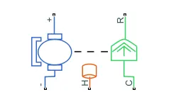
- This block represents the electrical and torque characteristics of a DC motor includes Thermal port to sence the temperature of Motor.
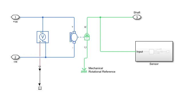
- The block assumes that no electromagnetic energy is lost, and hence the back-emf and torque constants have the same numerical value when in SI units. Motor parameters can either be specified directly, or derived from no-load speed and stall torque. If no information is available on armature inductance, this parameter can be set to some small non-zero value.
- When a positive current flow from the electrical + to - ports, a positive torque acts from the mechanical C to R ports. Motor torque direction can be changed by altering the sign of the back-emf or torque constants.
Sensor :
Subsystem :
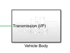
Vehicle Body :
Subsystem :
Blocks Used :
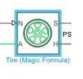
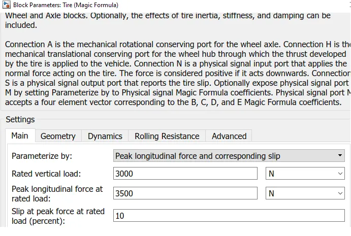
Tire :
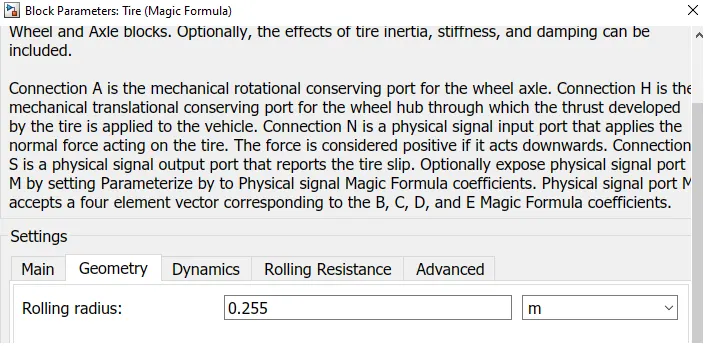
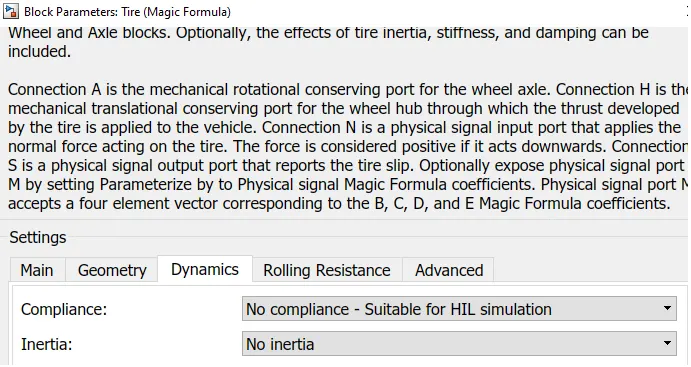
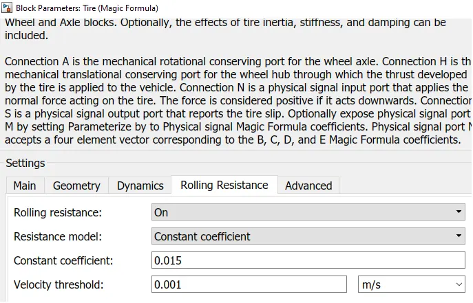
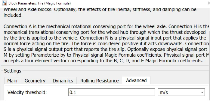
Vehicle Body :
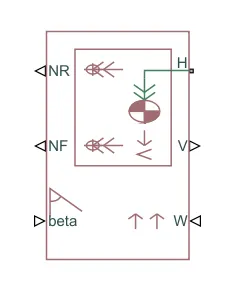
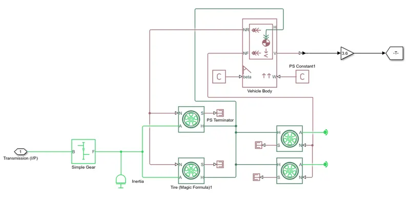
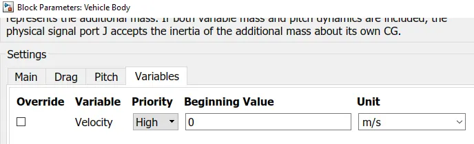
- This block basically represents a two-axle vehicle body in longitudinal motion. The block accounts for - body mass, aerodynamic drag, road incline, weight distribution between axles due to acceleration road profile.
- Here, the connection H is the mechanical translational conserving port hub. NF & NR correspond to the output ports for nomral reaction forces on front axle and rear axle wheels respectively.
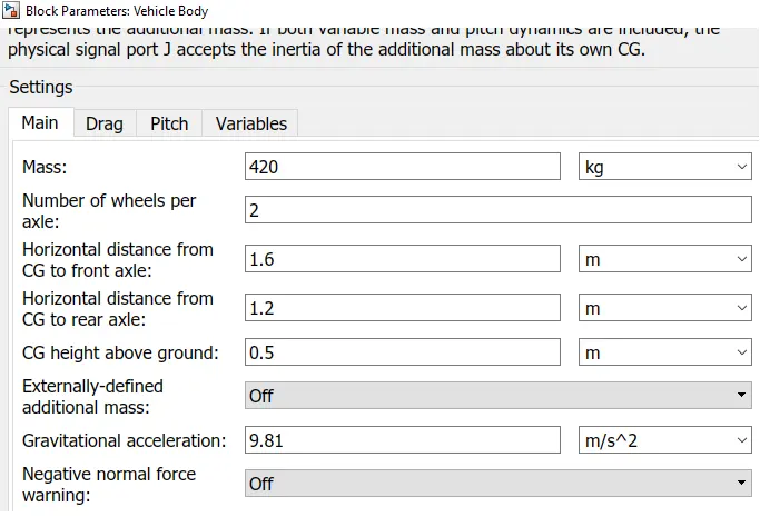
- Connection V represents the actual output translational velocity of the vehicle. beta is the road inclination angle & W corresponds to the headwind speed (headwind - direction opposite to that of vehicle). The gross weight is given to be 600 kg.
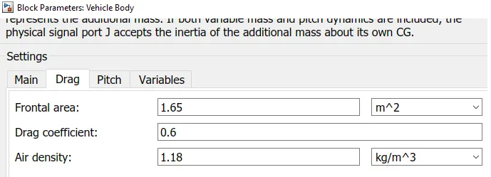
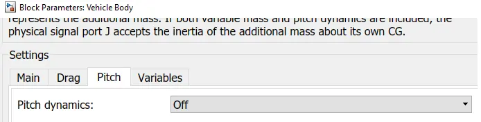
- The geometric parameters of the vehicle are given as -
Gear :
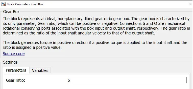
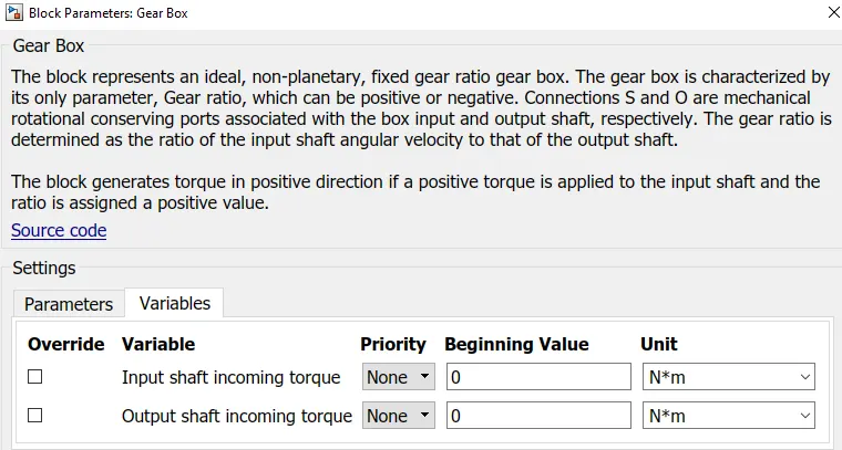
- Represents a fixed-ratio gear or gear box. No inertia or compliance is modeled in this block. You can optionally include gear
meshing and viscous bearing losses.
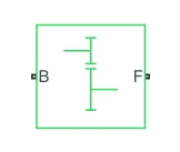
- Connections B (base) and F (follower) are mechanical rotational conserving ports. Specify the relation between base and follower rotation directions with the Output shaft rotates parameter.
- Optionally include thermal effects and expose thermal conserving port H by right-clicking on the block and selecting Simscape block choices to switch between variants. Output shaft rotates in in same direction of input shaft.
- Base is connected to the Motor shaft and the follower is connected to the Rear wheel derive.
Battery :
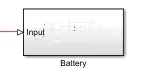
Subsystem :
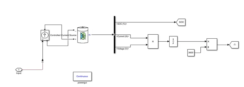
Blocks Used :
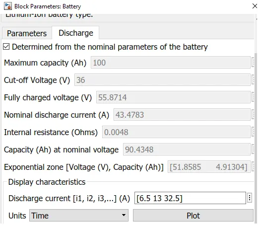
Battery :
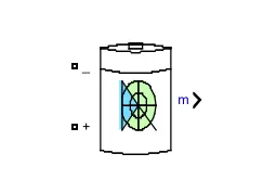
- The battery is required to power the controller and motor. The controller uses the battery power according to produce the input given by the motor to obtain maximum speed. The battery is also used to power every electrical component in the vehicle.
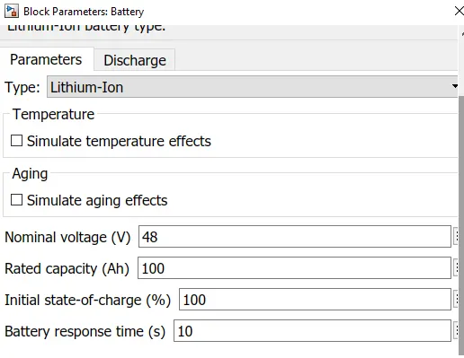
- The Battery block implements a generic dynamic model that represents most popular types of rechargeable batteries.
BUS Selector :
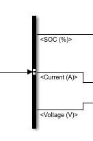
The Bus Selector block outputs the signals you select from the input bus. The block can output the selected elements separately or in a new virtual bus.
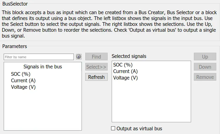
- Here just we have mange the output and connect with different Scope Block.
Controlled Current Source :

The Controlled Current Source block converts the Simulink input signal into an equivalent current source. The generated current is driven by the input signal of the block. The positive current direction is as shown by the arrow in the block icon.
We can initialize the Controlled Current Source block with a specific AC or DC current. If we want to start the simulation in steady state, the block input must be connected to a signal starting as a sinusoidal or DC waveform corresponding to the initial values.
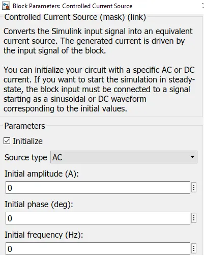
- Double click controlled current source and from drop down menu of measurement select current.
- Signal output will connect with scope by adding current signal to it.
- (+) terminal will connect with battery (-) terminal.
PowerGUI :
The powergui block allows us to choose one of these methods to solve your circuit :
- Continuous, which uses a variable-step solver from Simulink
- Discretization of the electrical system for a solution at fixed time steps
- Continuous or discrete phasor solution
The powergui block also opens tools for steady-state and simulation results analysis and for advanced parameter design.
Output Graphs :
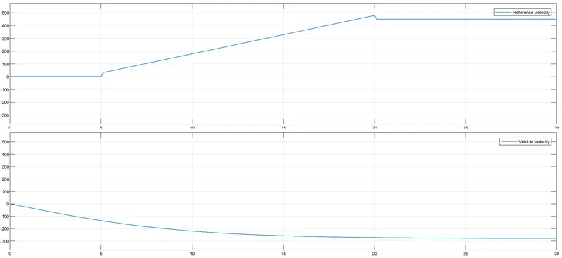
Reference Velocity and Vehicle Velocity :
Motor RPM :
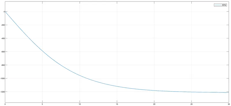
RPM is decreasing with the increase in load.
Battery SOC :
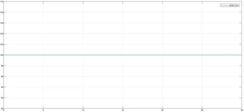
Battery SOC is 100% .
Avg. Energy Consumed :
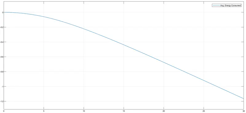
Avg. Energy Consumed is decreasing.