Project-1: Modelling an electric Car with Li-ion battery
AIM :
Create a MATLAB model of electric car which uses lithium ion battery and suitable motor. Choose suitable blocks from Simscape or Powertrain block set. Implement the vehicle speed control using PI controller and generate brake and accelerator commands. Avoid using readymade driver block for speed control.
INTRODUCTION :
An electric vehicle is a vehicle which uses battery as a power source. It uses electric motors for propulsion of the vehicle. The electricity stored in the battery and it is used to power the electric motors and the battery can be recharged. They are categorised into three different types Battery electric vehicles (BEV), Plugin hybrids electric vehicle (PHEV) and hybrid electric vehicle (HEV).
BATTERY ELECTRIC VEHICLES (BEV) :
Battery electric vehicles (BEV) are full electric vehicles with rechargable batteries and an electric motor with no combustion engines. It stores power in battery and this power is used to run the vehicle and other electronics present in the vehicle. These vehicles can be charged by electricity from external power source. These vehicles range for moderate km per charge. They don't emit any hazardous emissions. Some of the best examples of these cars are tesla, toyota prius, tata nexon EV, Volkswagon kona electric etc.
PLUG IN HYBRID ELECTRIC VEHICLE (PHEV) :
These types of vehicle have both electric motor and an internal combustion engine. They have batteries that can be charged with regenerative braking or with a external power supply. These vehicles can go from 10 - 30 on an average with electric motor before the assistance of an combustion engine. Some of the best examples of these cars are Toyota camry hybrid, Honda civic hybrid, Volvo XC90, maruti suzuki ciaz mild hybrid etc.
HYBRID ELECTRIC VEHICLE (HEV) :
These types of vehicle get powered by both electric motor and internal combustion engine. Battery can be recharged with regenerative braking only. Electric motor supplies power for starting and the internal combustion engine takes place when there is heavy load and on high speeds. Controller is used to ensure the best economy. Some of the best examples are honda accord hybrid, hyundai sonata hybrid, toyota camry hybrid etc.
BENEFITS OF ELECTRIC VEHICLE :
- An electric vehicle has fewer moving parts than a conventional petrol/diesel car. Servicing is relatively easy, less frequent and overall cheaper to maintain a electric car when compared to a petrol/diesel vehicle.
- All EV batteries degrade it becomes less efficient. Most car manufacturers give an warrant for the batteries that it will npt degrade below a certain level for around 10 years. It is also necessary to replace a battery in a EV in time after years.
- The cost of electricity required to charge an EV is around 40% - 60% less than the cost of the petrol for a similar sized vehicle driving for a same distance. The cost will get very lower when charging the vehicle at free charging stations too.
- They produce no air pollution and it will decrease global warmings.
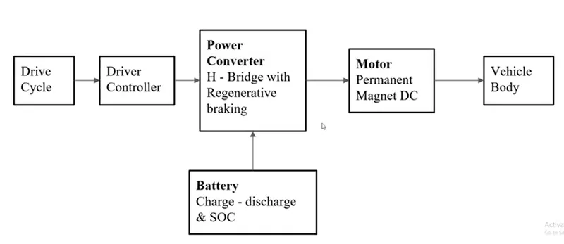
The Block diagram of the electric car is shown below.
- The EV range test is done at a steady of 60-70 mph because highway driving is were range is necessary. When a person is looking to cover a range of 700 - 1000kms in a day means that a person should travel at higher speeds to cut the time. EVs consumption of power is drastically increased when the speed rises, as the aerodynamic drag inflates with the square of speed.
MODEL OF AN ELECTRIC CAR IN MATLAB-SIMULINK :
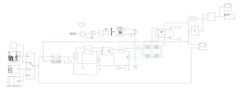
The simulink model of an electric car with lithium ion battery is given below...
COMPONENTS USED IN A ELECTRIC VEHICLE :
Drive cycle source :
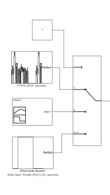
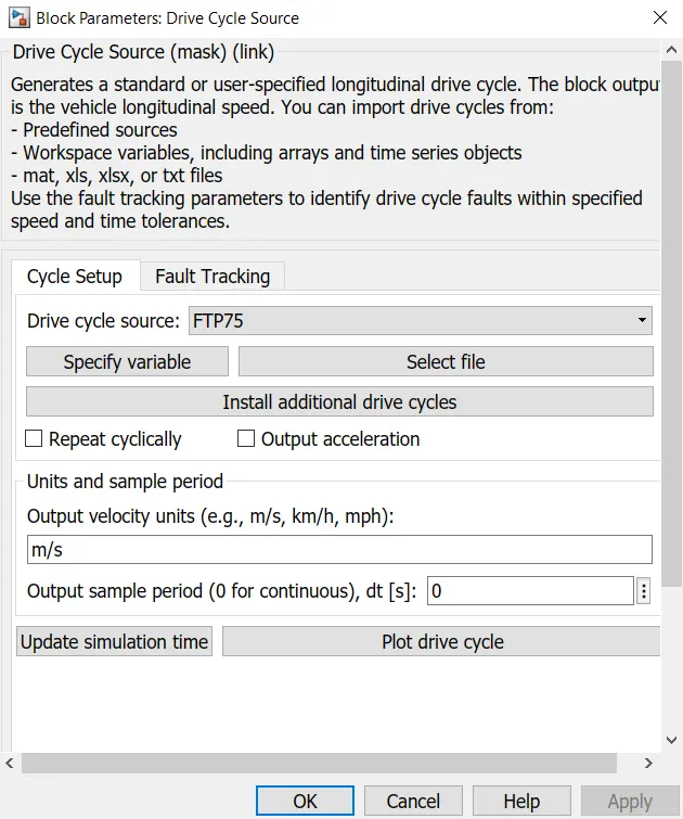
There are three types of velocity reference given to the system, I have used default driving source block, from the drive cycle source were the one is FTP75 and wide open throttle (WOT) and the third is given as constant value.
DRIVE SOURCE BLOCK :
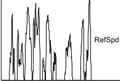
- This block generates a standard or user specified longitudinal drive cycle. Drive cycles from predefined sources which will give default block of FTP75. .mat, .xlsx, or .txt blocks can be used through this from spreadsheet block.
The drive cycle are having the the modes as shown below.
MULTIPORT SWITCH BLOCK :
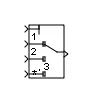
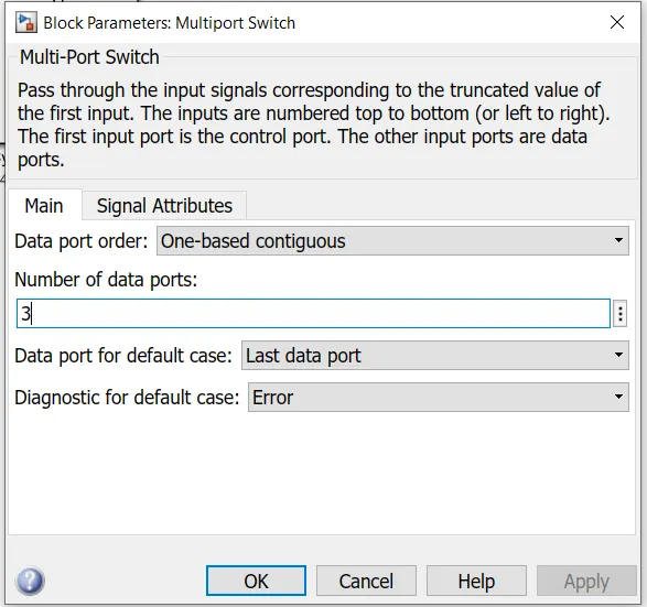
- This block is used to slect how many number of input that passes through this block. This first input in the block is used to choose which input value should be taken. The first input is the control input and the remaining inputs are the data inputs. The value of the control input decides which input has to be passes to the output.
PID CONTROLLER :
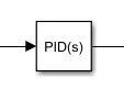
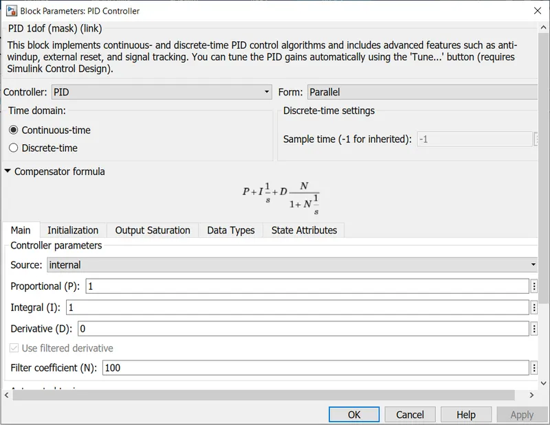
- Proportional intergral derivative (PID) controllers can be attributed partly to the wide range of operating conditions and partly to the functional simplicity.
- PROPORTIONAL RESPONSE : The proportional component depends only on the difference between the set point and the process variable. The proportional gain K_c determines the ratio of the output response to the error signal.
- INTEGRAL RESPONSE : The integral component sums the error term over time. The result is that even a small error term will cause the integral component to increase slowly. The integral response will continously increase over time unless the error is zero, so the effect is to drive the steady state error to zero.
- DERIVATIVE RESPONSE : The derivative component causes the output to decrease if the process variable is increasing rapidly. The derivative response is proportional to the rate of change of the process variable.
MOTOR AND ITS CONTROLLER :
CONTROLLED PWM VOLTAGE :

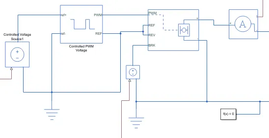
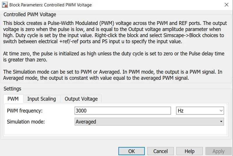
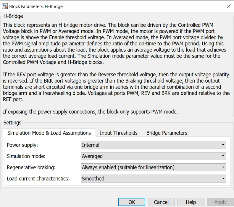
This Block will create Pulse width modulation (PWM) signal across the PWM and REF ports. The output voltage is zero when the pulse is low and equal to the output voltage amplitude parameter when high. At time zero the pulse is initialized as high unless the duty cycle is set to zero or the pulse delay time is greater than zero. The simulation mode is choosen as averaged where the output signal will be constant with value equal to the averaged PWM signal.
H-BRIDGE :
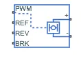
H-bridge is a electronic circuit which enables to apply voltage to load in either direction. It is commonly used to control DC motors. By using H-bridge the DC motor can be used to run in clockwise and in anti clockwise directions. This block is also used to produce alternating waveforms. For averaged simulation mode the load current characteristics is set to smoothed rather than discontinous.
DC MOTOR :
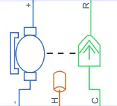
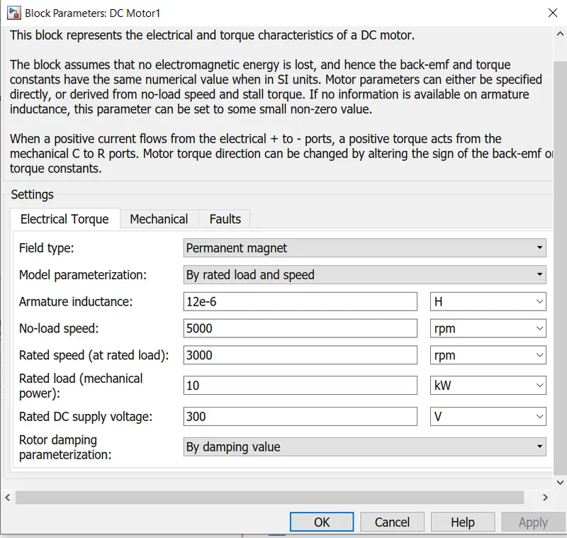
This block constitute both the electrical and torque characteristics of DC motor. There will no electromagnetic energy is lost, and hence the back-emf and torque constants have the same numerical value in SI units. The type of motor choosen is the permanent magnet type so it resemblance the BLDC type of motor which is commonly used in electric vehicles.
CONTROLLED VOLTAGE SOURCE :

This block represents an ideal voltage source that is powerful to maintain the specified voltage at the output of the current passing through it. Two control voltage sourse block is used, one for the drive controlled PWM voltage source and the other block is used in braking command of the h-bridge. The respective voltage of the block is controlled as per the acceleration command and the deceleration command of the longitudinal driver.
CURRENT SENSOR :

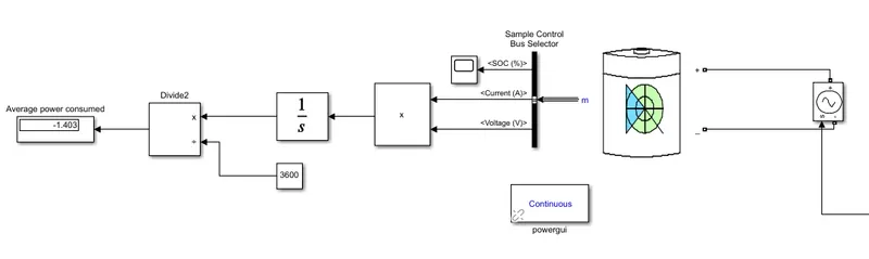
This block represents ideal current sensor, which converts current measured in any electrical branch into physical signal proportional to the current. Both positive and negative are conserving electrical ports through which the sensor is inserted into the circuit. The positive and the negative port of this block is connected between H-bridge and the DC motor whereas the physical port 'I' is connected to the controlled current source of the battery management system.
VEHICLE DYNAMICS :
VEHICLE BODY :
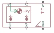
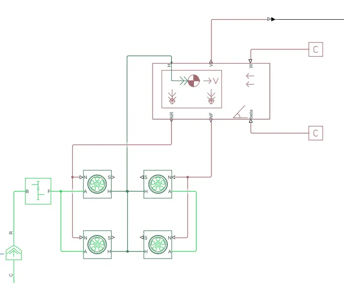
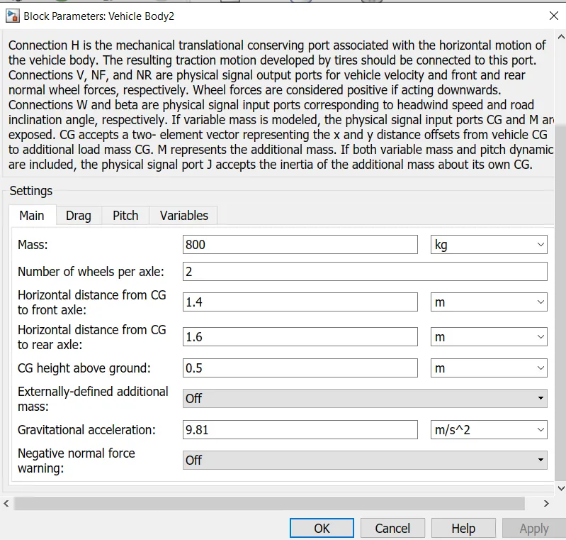
This block represents a two axle vehicle body in longitudinal motion. The block accounts for body mass, aerodynamic drag, road incline and weight distribution between axles due to acceleration and road profile. This blocks gives the option of having the same or a different number of wheels on each axle with optional inclusion of pitch and suspension dynamics or additional variable mass and inertia. This block consists of an total of 6 connection port, out of which H is the mechanical translational conserving port associated with the horizontal motion of the vehicle body and its connected to the H port of the wheel hub of the tire through which the resulting traction motion of the tires will get generated. V is the physical output port which is used to examine and monitor the vehicle velocity curve, NF and NR are also physical output ports but they represent front and rear normal wheel forces and due to this reason they are connected to the N of the tires through the forces will get act on the wheel for rotation. W and beta are physical signal input ports corresponding to headwind speed and road inclination angle.
TIRE (MAGIC FORMULA) :

The tire magic formula block can model tire dynamics under constant or variable pavement conditions. The longitudinal direction of the tire is the same as its direction of motion as it rolls on pavement and to increase the fidelity of the tire model, the properties can be specified such as tire compliance, inertia and rolling resistance.
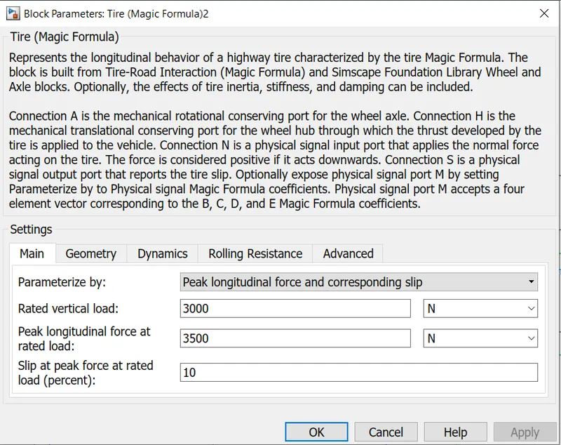
This also consists of 4 connection port out of which A is the mechanical rotational conserving port for the wheel axle and it is connected to the gear arrangement of the vehicle. H is the mechanical translational conserving port for the wheel hub through which trust is developed by the tires of the vehicle and it is connected to the H port of the vehicle body for initiation of the horizontal motion. N is the physical signal input port that applies the normal force acting on the tire and it is connected to the NR and NF of the vehicle body.
SIMPLE GEAR :

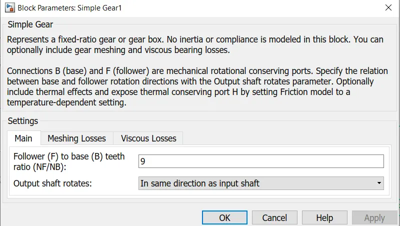
This block represents a fixed ratio gear or gear box. No inertia od compliance is modeled in this block. Connections B(base) and F(follower) are mechanical rotational conserving ports which are connected to the shaft input of the DC motor and A port of the wheel and axle.
INERTIA :

This block represents an ideal mechanical rotational inertia. This block positive direction is from its port to the reference point which means that the inertia torque is positive if the inertia is accelerated in the positive direction.
BATTERY MANAGEMENT SYSTEM :
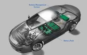
- The BMS will also control the recharging of the battery by redirecting the recovered energy (from regenrative braking) back into the battery pack. Battery thermal management system can be either passive or active and the cooling medium can either be air, liquid or some change of phase change.
- Air cooling is advantageous in its simplicity such systems can be passive, relying only on the convection of the surrounding air or active, utilizing fans for airflow. The major disadvantage of air cooling is its inefficiency. Large amounts of power must be used to operate the cooling mechanism far more than active liquid cooling.
- The additional components of the cooling mechanism also add weight to the BMS, reducing the efficiency of batteries used for transportation. Liqiud cooling has a higher ntural cooling potential than air cooling as liquid coolants tend to have higher thermal conductivities thaan air.
- The batteries can either be directly submerged in the coolant or coolant can flow through the BMS without directly contacting the battery. Indirect cooling has the potential to create large thermal gradients across the BMS due to increased length of the cooling.
BATTERY :
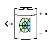
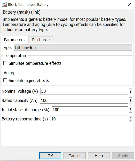
The internal resistance is assumedto be constant during the charge and discharge cycles and does not vary with the ampitude of the current. The discharging and charging characteristics are assumed to be the same. The capacity of the battery does not change with the ampitude of the current. When the battery gets charged then there is a exponential voltage drop and the width of the drop is depends upon the battery type. The positive terminal of the battery is connected to the controlled current source block where the current is controlled as per the voltage of the DC motor.
CONTROLLED CURRENT SOURCE :

THis block is responsible converting the simulink input signal into an equivalent current source. The generated current is driven by the input signal of the block. The positive and negative terminals of the block is connected across the battery and the physical port S is connected to the physical output I of the current sensor of the DC motor subsystem.
INTEGRATOR :

This block produces the output of the intergral of its input signal with respect to time. The selected solver computes the output of the integrator block at the current time step, using the current input value and the value of the state at the previous time step.
RESULTS :
CASE 1: THE DRIVE CYCLE SOURCE IS FTP75 :
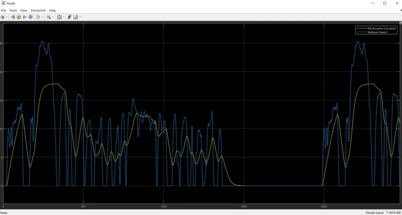
The blue line of the graph drive cycle source and ywllow line shows the corresponding velocity graph. The drive cycle input and output velocity graph is exactly overlapping on each other. Thus from the above figure it is clear that the error in the velocity output is get reduced to a great extent.
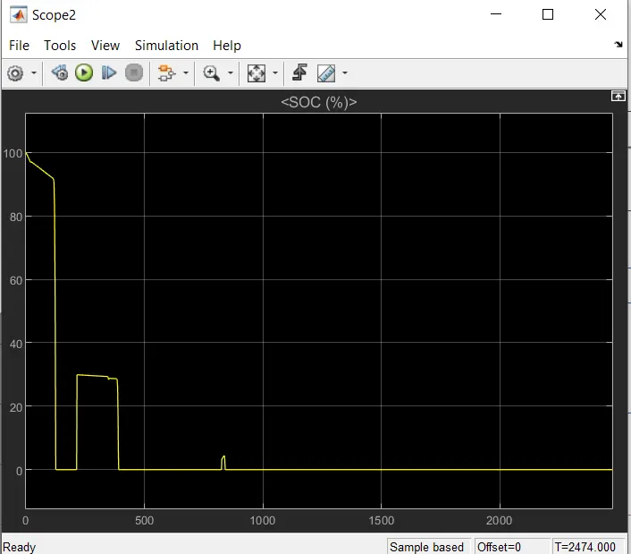
The variation of the SOC is shown below.
CASE 2: THE SIGNAL BUILDER :
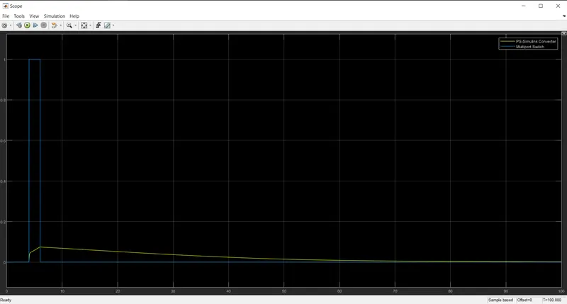
The yellow line shows the distance covered by an electric vehicle.
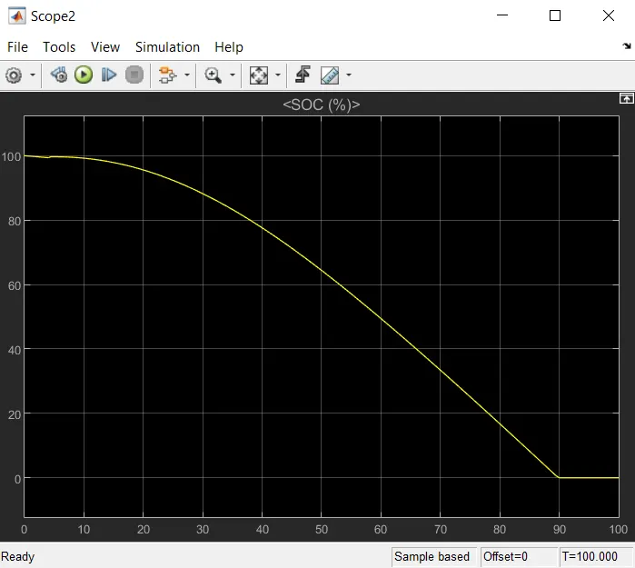
The variation in SOC is shown below.
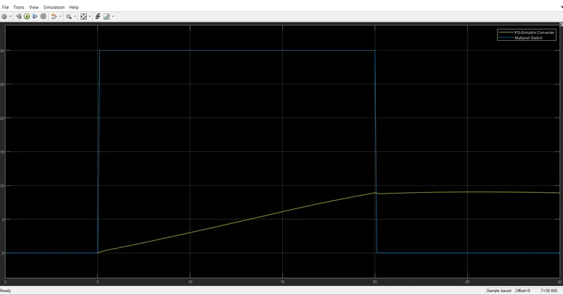
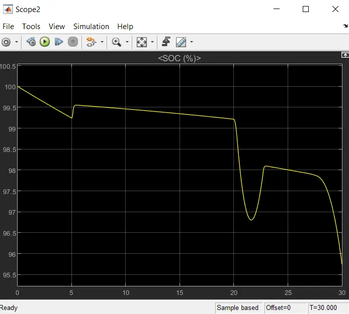
CASE 3: WIDE OPEN THROTTLE :
The variation in SOC is shown below.
CONCLUSION :
So the performance characteristics of the MATLAB electric car with lithium ion model is sucessfully implemented by taking various drive cycle source and the results are detailed analysis and discussed.
LINK : https://drive.google.com/file/d/1ck2Qq2492IrtE8Tq4WBVmw2l9Nmdmhic/view?usp=sharing