Project-1: Modelling an electric Car with Li-ion battery
Create a MATLAB model of electric car which uses lithium ion battery and suitable motor. Choose suitable blocks from Simscape or Powertrain block set. Implement the vehicle speed control using PI controller and generate brake and accelerator commands.
Objective: To prepare a report on EV simulink model using lithium ion battery.
- System level configurations
- Model parameters
- Results
- Conclusion.
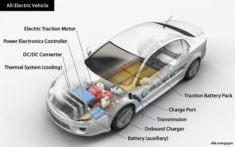
All-electric vehicles (EVs) have an electric motor instead of an internal combustion engine. The vehicle uses a large traction battery pack to power the electric motor and must be plugged into a charging station or wall outlet to charge. Because it runs on electricity, the vehicle emits no exhaust from a tailpipe and does not contain the typical liquid fuel components, such as a fuel pump, fuel line, or fuel tank.
All-electric vehicles (EVs) use a battery pack to store the electrical energy that powers the motor. EVs are sometimes referred to as battery electric vehicles (BEVs). EV batteries are charged by plugging the vehicle into an electric power source. Although electricity production may contribute to air pollution, the U.S. Environmental Protection Agency categorizes all-electric vehicles as zero-emission vehicles because they produce no direct exhaust or emissions.
Both heavy-duty and light-duty EVs are commercially available. EVs are typically more expensive than similar conventional and hybrid vehicles, although some cost can be recovered through fuel savings, a federal tax credit, or state incentives.
Components of EV
Battery (all-electric auxiliary):
In an electric drive vehicle, the auxiliary battery provides electricity to power vehicle accessories.
Charge port:
The charge port allows the vehicle to connect to an external power supply in order to charge the traction battery pack.
DC/DC converter:
This device converts higher-voltage DC power from the traction battery pack to the lower-voltage DC power needed to run vehicle accessories and recharge the auxiliary battery.
Electric traction motor:
Using power from the traction battery pack, this motor drives the vehicle’s wheels. Some vehicles use motor generators that perform both the drive and regeneration functions.
Onboard charger:
Takes the incoming AC electricity supplied via the charge port and converts it to DC power for charging the traction battery. It monitors battery characteristics such as voltage, current, temperature, and state of charge while charging the pack.
Power electronics controller:
This unit manages the flow of electrical energy delivered by the traction battery, controlling the speed of the electric traction motor and the torque it produces.
Thermal system (cooling):
This system maintains a proper operating temperature range of the engine, electric motor, power electronics, and other components.
Traction battery pack:
Stores electricity for use by the electric traction motor.
Transmission (electric):
The transmission transfers mechanical power from the electric traction motor to drive the wheels.
Driving Range
Today’s EVs generally have a shorter range (per charge) than comparable conventional vehicles have (per tank of gas). The efficiency and driving range of EVs vary substantially based on driving conditions. Extreme outside temperatures tend to reduce range because more energy must be used to heat or cool the cabin. High driving speeds reduce range because of the energy required to overcome increased drag. Compared with gradual acceleration, rapid acceleration reduces range. Hauling heavy loads or driving up significant inclines also reduces range.
Simulation model and its block details:
First we need to build the vehicle body because, we have to know the power ratings of the motor while the vehicle running onthe roads.
create the subsystem of vehicle body.
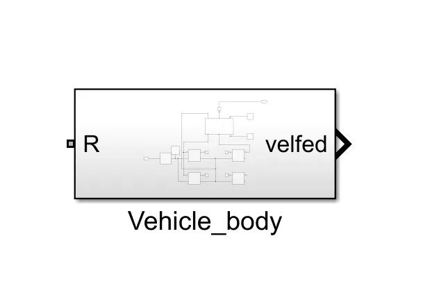
inside this...
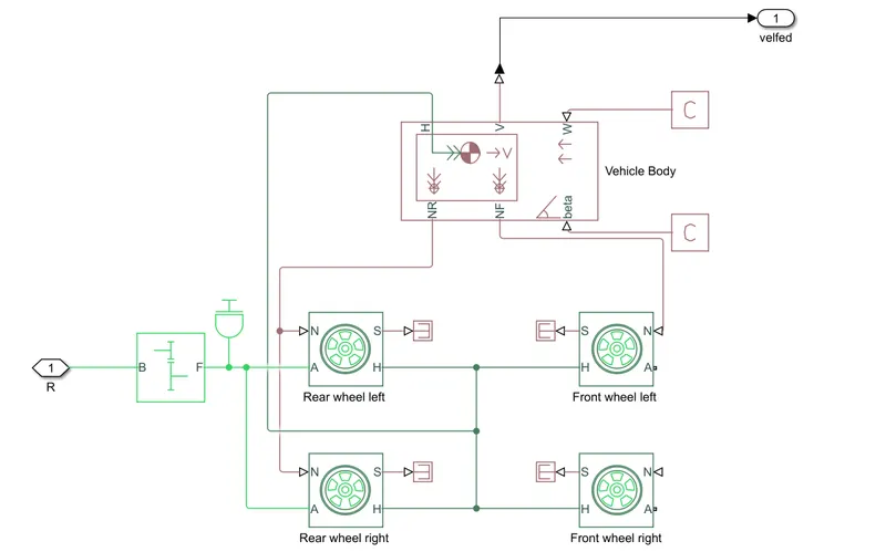
this is the total subsystem of the vehicle body.
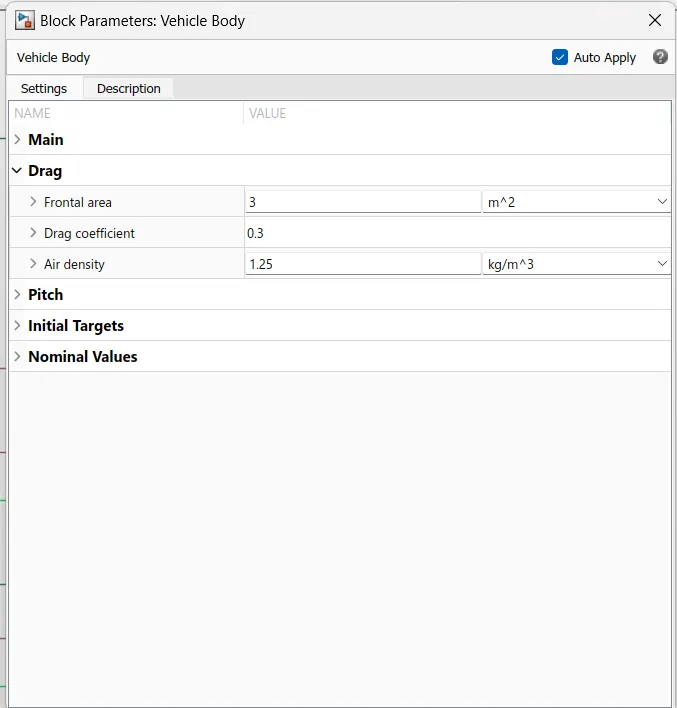
vehicle body system block parameters have been discussed below
Vehicle body:
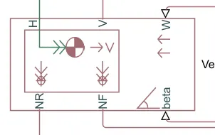
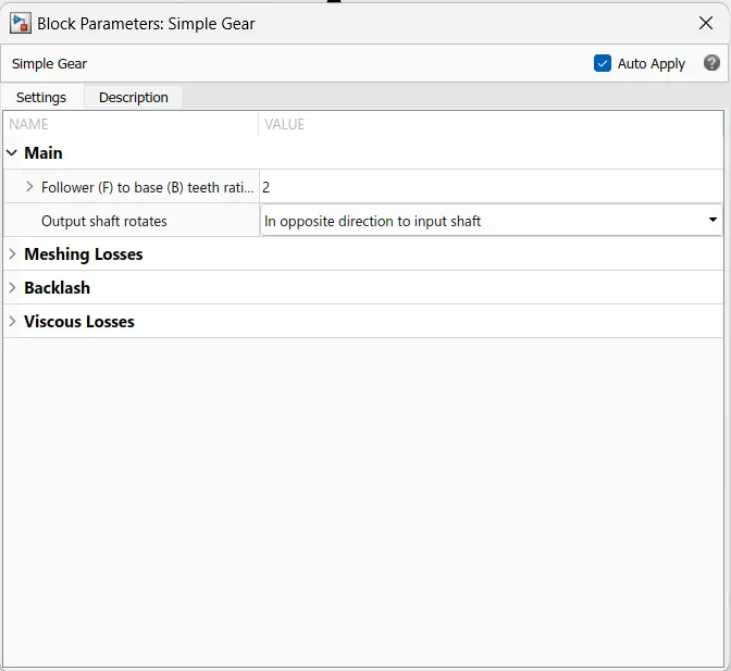
Simple Gear
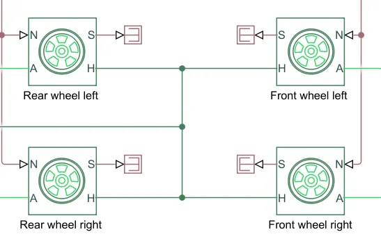
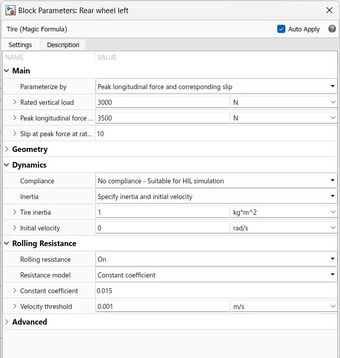
Tire:
DC motor:
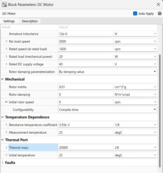
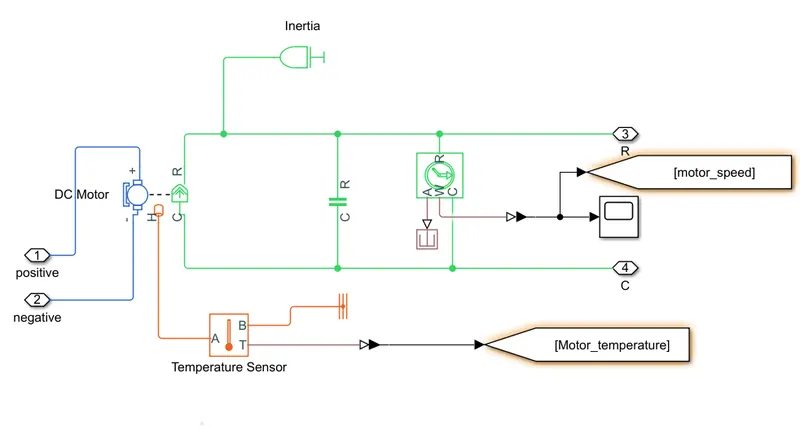
DC motor sub system:
Motor Controller
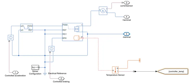
H-Bridge circuit:
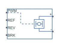
The H-Bridge block represents an H-bridge motor driver. The block has the following two Simulation mode options:
-
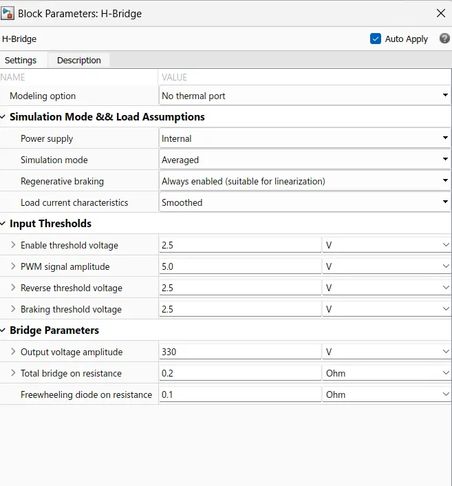
PWM— The H-Bridge block output is a controlled voltage that depends on the input signal at the PWM port. If the input signal has a value greater than the Enable threshold voltage parameter value, the H-Bridge block output is on and has a value equal to the value of the Output voltage amplitude parameter. If it has a value less than the Enable threshold voltage parameter value, the block maintains the load circuit using one of the following three Freewheeling mode options:-
Via one semiconductor switch and one freewheeling diode -
Via two freewheeling diodes -
Via two semiconductor switches and one freewheeling diode
The first and third options are sometimes referred to as synchronous operation.
The signal at the REV port determines the polarity of the output. If the value of the signal at the REV port is less than the value of the Reverse threshold voltage parameter, the output has positive polarity; otherwise, it has negative polarity.
-
The block can be driven by the controlled PWM Voltage block in PWM or Averaged mode.
- In PWM mode, the motor is powered if the PWM port voltage is above the enabled threshold voltage.
- In Averaged mode, the PWM port voltage divided by the PWM signal amplitudes parameter defines that the ratio of on time yo the PWM period.
- Connection REF is for the Reference input. This combined with the Pwm connected will form the pulse input for the H Bridge.It is Electrical Reference
- Connection REV corresponds to the reverse motion of the motor which essentially means, the backward motion of the vehicle. Here the backward motion of the vehicle is not accounted for and so the port is connected to the electrical reference.
- Connection BRK is for the braking the Vehicle
- The PWM mode results in a huge amount of simulation time. Averaged mode is selected for this simulation.
- Load current characteristics are considered to be smoothed here.
- The regenerative braking is enabled for the simulation. This means when the vehicle starts decelerating corresponding amount of charge will be fed back to the battery.
- BRK input is connected to a controlled Voltage Source. This will generate emf corresponding to the intensity of brakes applied and fed the power back to the battery.
block paremeters of H-bridge:
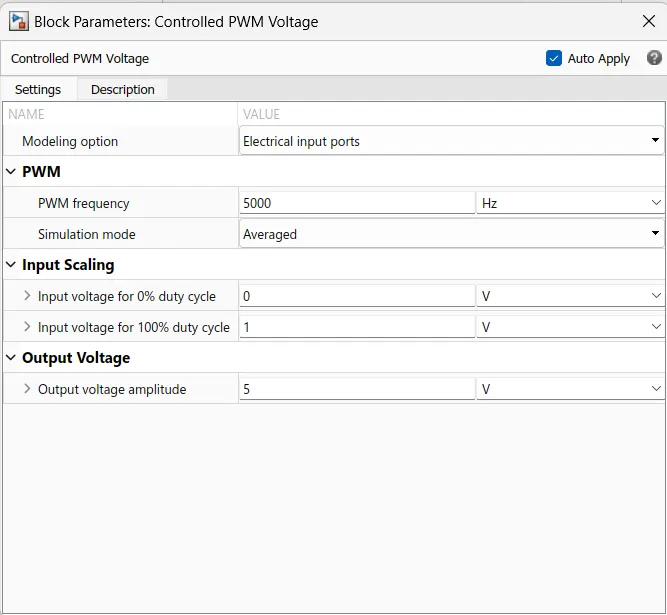
Controlled PWM Voltage block
Simulink provides an inbuilt Controlled PWM Voltage block. This block is used for providing the proper pulse input to the block
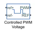
The Controlled PWM Voltage block represents a pulse-width modulated (PWM) voltage source.
-
Electrical input ports — The block calculates the duty cycle based on the reference voltage across its ref+ and ref- ports. This modeling variant is the default.
-
PS input — Specify the duty cycle value directly by using an input physical signal port.
The PWM and REF connection are for the corresponding ports on the H-Bridge Circuit.The two reference inputs corresponds to the throttle inputs given by the driver.The block generates corresponding pulse width as per the acceleration and brakes applied by the driver himself.Here the PWM frquency is 4000Hz. Also the simulation mode is Averaged as that in the H-Bridge circuit.
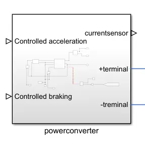
Total subsystem of power converter
Battery:
A lithium-ion (Li-ion) battery is an advanced battery technology that uses lithium ions as a key component of its electrochemistry. During a discharge cycle, lithium atoms in the anode are ionized and separated from their electrons. The lithium ions move from the anode and pass through the electrolyte until they reach the cathode, where they recombine with their electrons and electrically neutralize. The lithium ions are small enough to be able to move through a micro-permeable separator between the anode and cathode. In part because of lithium’s small size (third only to hydrogen and helium), Li-ion batteries are capable of having a very high voltage and charge storage per unit mass and unit volume.
here, we are using datasheet battery system because it implements the lithium ion, lithium-polymer, or lead-acid battery that you can parameterize using manufacturer data.
PID Controller Subsystem:
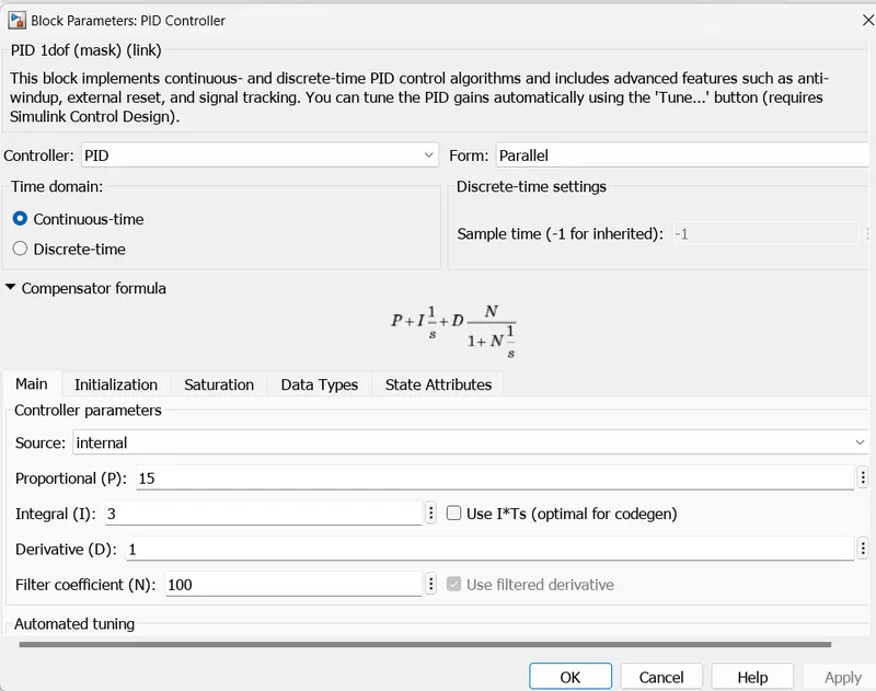
The Discrete PID Controller block implements a PID controller (PID, PI, PD, P only, or I only). The block is identical to PID Controller block with the Time domain parameter set to Discrete-time.
The block output is a weighted sum of the input signal, the integral of the input signal, and the derivative of the input signal. The weights are the proportional, integral, and derivative gain parameters. A first-order pole filters the derivative action.
The block supports several controller types and structures. Configurable options in the block include:
-
Controller type (PID, PI, PD, P only, or I only)
-
Controller form (Parallel or Ideal)
-
Time domain (continuous or discrete)
-
Initial conditions and reset trigger
-
Output saturation limits and built-in anti-windup mechanism
-
Signal tracking for bumpless control transfer and multiloop control
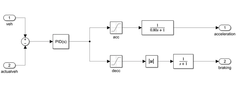
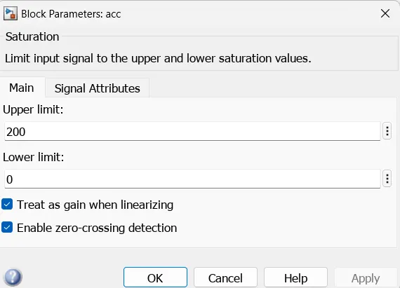
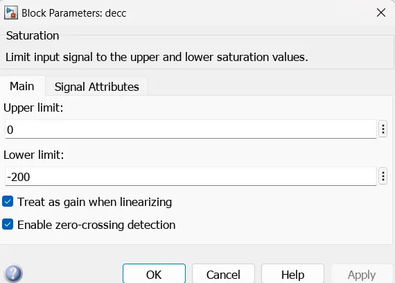
The saturation block is used for upper limit and lower limits for bounded input and output signals
Block parameter for acceleration:
Block parameter for deceleration:
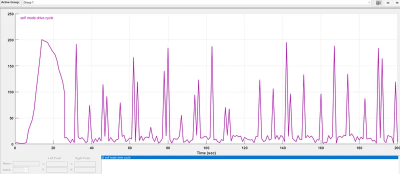
Drive cycle source:
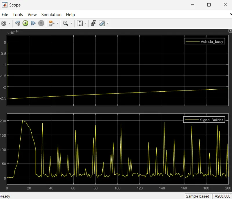
here i used signal builder block to make drive cycle
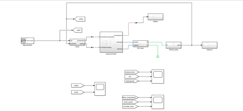
Complete model:
Results:
Drive cycle input:
Gain of the battery system:

Voltage

current

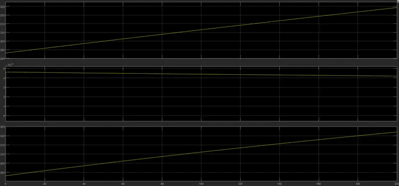
in the above results first one is the motor temperature, second is the motor speed, last one is the controller temperature.