Project-1: Modelling an electric Car with Li-ion battery
AIM : To build a electric vehicle with the li-ion battery and suitable motor by using simulink model parameters
objective
Create a MATLAB model of electric car which uses lithium ion battery and suitable motor. Choose suitable blocks from Simscape or Powertrain block set. Implement the vehicle speed control using PI controller and generate brake and accelerator commands. Avoid using readymade driver block for speed control.
Prepare a report about your model including following:
Objectives, System level configurations, Model parameters, Results, Conclusion.
Electric car
An electric vehicle (EV) is a vehicle that uses one or more electric motors for propulsion . It can be powered by a collector system with electricity from extravehicular sources, or it can be powered autonomously by a battery(sometimes charged by solar panels or by converting fuel to electricity using fuel cell or a generator.
EVs include, but are not limited to, road and rail vehicles surface and underwater vessels, electric craft and electric space craft .
For road vehicles, together with other emerging automotive technologies such as autonomous driving, connected vehicles and shared mobility, EVs form a future mobility vision called Connected, Autonomous, Shared and Electric (CASE) Mobility.
Motor
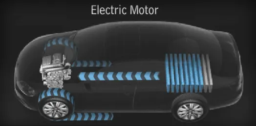
All-electric vehicles (EVs) have an electric motor instead of an internal combustion engine. The vehicle uses a large traction battery pack to power the electric motor and must be plugged into a charging station or wall outlet to charge. Because it runs on electricity, the vehicle emits no exhaust from a tailpipe and does not contain the typical liquid fuel components, such as a fuel pump, fuel line, or fuel tank.
Efficiency of charging varies considerably depending on the type of charger, and energy is lost during the process of converting the electrical energy to mechanical energy.
Usually, direct current (DC) electricity is fed into a DC/AC inverter where it is converted to alternating current (AC) electricity and this AC electricity is connected to a 3-phase AC motor.
For electric trains, forklift trucks, and some electric cars, DC motors are often used.
In some cases, universal motors are used, and then AC or DC may be employed.
In recent production vehicles, various motor types have been implemented; for instance, induction motors within Tesla Motor vehicles and permanent magnet machines in the Nissan Leaf and Chevrolet Bolt.
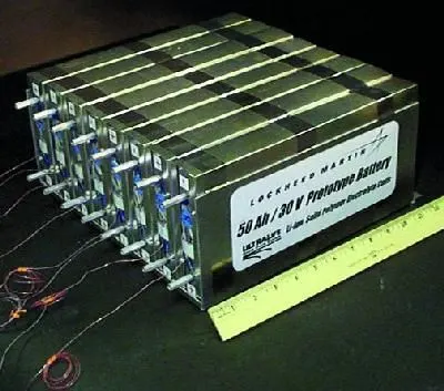
Lithium ion:Most electric vehicles use lithium-ion batteries (Li-Ions or LIBs). Lithium ion batteries have higher energy density, longer life pan and higher power density than most other practical batteries. Complicating factors include safety, durability, thermal breakdown, its environmental impact and cost. Li-ion batteries should be used within safe temperature and voltage ranges in order to operate safely and efficiently.Increasing the battery's lifespan decreases effective costs. One technique is to operate a subset of the battery cells at a time and switching these subsets.In the past, nickel–metal hydride batteries were used in some electric cars, such as those made by General Motors. These battery types are considered outdated due to their tendencies to self-discharge in the heat. Furthermore, a patent for this type of battery was held by Chevron, which created a problem for their widespread development. These factors, coupled with their high cost, has led to lithium-ion batteries leading as the predominant battery for EVs.The prices of lithium-ion batteries are constantly decreasing, contributing to a reduction in price for electric vehicles.
Components:
| Blocks | Quantity |
| vehicle body | 1 |
| Tire (Magic Formula) | 4 |
| simple gear | 1 |
| inerta | 1 |
| ps constant | 2 |
| ps terminator | 4 |
| H bridge | 1 |
| controlled pwm voltage | 1 |
| DC motor | 1 |
| current sensor | 1 |
| controlled voltage source | 2 |
| Battery | 1 |
| controlled current source | 1 |
| powergui | 1 |
| solver configartion | 1 |
All blocks aare used from Simulink, Powertrain, and Simscape libraries
Model Parameters:
| Block | configaration |
| vehicle configaration | m= 800kg,remaining default |
| Tire | default |
| simple gear | default |
| controlled pwm voltage | pwm frequency=2000Hz, output voltage = 200v remaining default |
| DC motor |
field type = permanant magnet No-load speed = 3000rpm rated speed = 2000rpm rated load = 20kW rated DC supply voltage = 200v remaining default |
| solver configuration | default |
| Battery |
Type = Lithium ion nominal voltage = 200v rated capacity = 100Ah remaining default |
| PID Controller |
Type = PI Time domain continuous proportional (P) = 12 Integral (I) = 0.0001 |
| acceleration saturation |
upper limit = 1 lower limit = 0 |
| Decelleration saturation |
upper limit = 0 lower limit = -1 |
| accel Transfer function |
1/(s+1) |
| Deccel Transfer function |
1/(s+2) |
| Drive cycle source |
FTP75 2474 seconds |
Procedure:
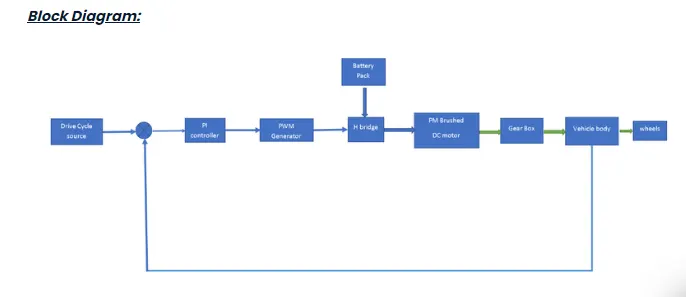
The Motor controller will get input from the longitudinal driver. Its tasks are to control the speed of the motor and drive according to the input of the driver.
- Majorly motor controlled we designed had two main parts named PWM voltage generator and H-Bridge Input 1 is getting from the acceleration of a longitudinal driver and it is given to a controlled voltage source block where it is input to the controlled PWM voltage will generate a PWM signal in such a way that H-bridge will generate the required voltage to operate the DC motor for the given driver input
- PWM voltage block negative reference and REF are grounded and REF of H bridge respectively. H-bridge is a motor controller that has IGBT components aligned in the shape of H and will operate only two at a time respectively to the input of the signal from the PWM block.
- When deceleration occurs this H-bridge will give an output from the positive and negative terminals of it. These negative & positive terminals are later connected to the DC motor and battery. All these components are the simscape electrical components so they need a connection to the solver configuration block which helps to solve the simulation.
This is the DC Motor that would give rotational power to the wheels and become the sole power generation source.
The DC Motors terminals are connected as mentioned below.
+ =Electrical signal to the motor Positive Terminal
- =Electrical signal to the motor Negative Terminal
R=Casing of the Motor connected with the Mechanical Rotational Reference Block
C=Rotor Case connected to the Mechanical Rotational reference
The PI controller is tuned as per the drive cycle source
System level configaration:
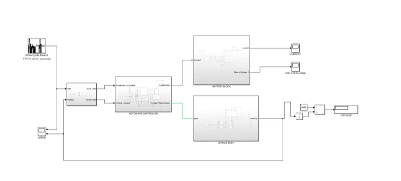
Let us see the subsystems
subsystem of vehicle body
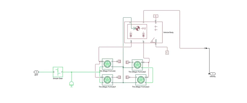
vehicle body is connected with the four wheels as shown in the figure
a simple gear with gear ratio 2 is connected between motor and differential
the pwm generator is connected to the h bridge so that it can generate the firing angle and the hbridge is connected to the permanant magnet brushed DC motor and it is fed to the simple gear
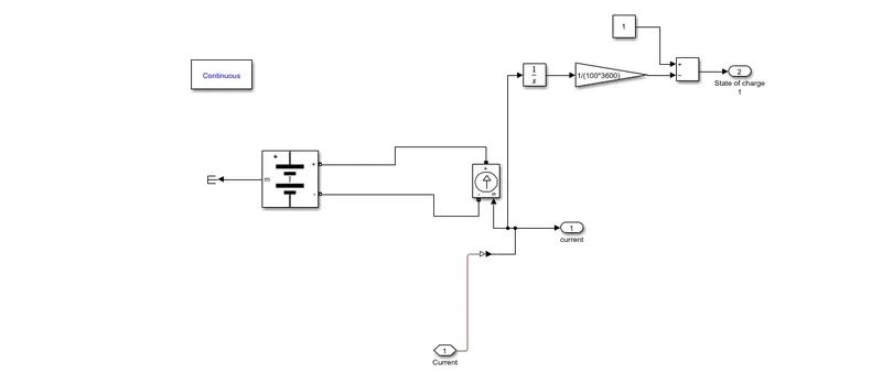
subsystem of battery
H-Bridge circuit:
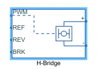
The H-Bridge block represents an H-bridge motor driver. The block has the following two Simulation mode options:
-
PWM— The H-Bridge block output is a controlled voltage that depends on the input signal at the PWM port. If the input signal has a value greater than the Enable threshold voltage parameter value, the H-Bridge block output is on and has a value equal to the value of the Output voltage amplitude parameter. If it has a value less than the Enable threshold voltage parameter value, the block maintains the load circuit using one of the following three Freewheeling mode options:-
Via one semiconductor switch and one freewheeling diode -
Via two freewheeling diodes -
Via two semiconductor switches and one freewheeling diode
The first and third options are sometimes referred to as synchronous operation.
The signal at the REV port determines the polarity of the output. If the value of the signal at the REV port is less than the value of the Reverse threshold voltage parameter, the output has positive polarity; otherwise, it has negative polarity.
-
-
Averaged— This mode has two Load current characteristics options:-
Smoothed -
Unsmoothed or discontinuous
-
The block can be driven by the controlled PWM Voltage block in PWM or Averaged mode.
- In PWM mode, the motor is powered if the PWM port voltage is above the enabled threshold voltage.
- In Averaged mode, the PWM port voltage divided by the PWM signal amplitudes parameter defines that the ratio of on time yo the PWM period.
- Connection REF is for the Reference input. This combined with the Pwm connected will form the pulse input for the H Bridge.It is Electrical Reference
- Connection REV corresponds to the reverse motion of the motor which essentially means, the backward motion of the vehicle. Here the backward motion of the vehicle is not accounted for and so the port is connected to the electrical reference.
- Connection BRK is for the braking the Vehicle
- The PWM mode results in a huge amount of simulation time. Averaged mode is selected for this simulation.
- Load current characteristics are considered to be smoothed here.
- The regenerative braking is enabled for the simulation. This means when the vehicle starts decelerating corresponding amount of charge will be fed back to the battery.
- BRK input is connected to a controlled Voltage Source. This will generate emf corresponding to the intensity of brakes applied and fed the power back to the battery.
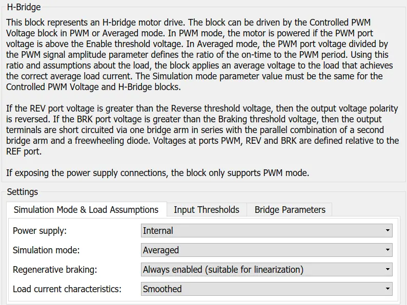
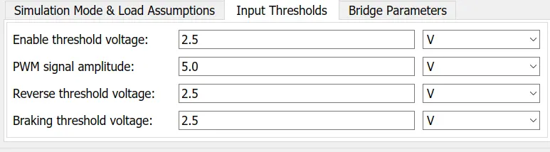
The Input Threshold Parameters are left with their default values.
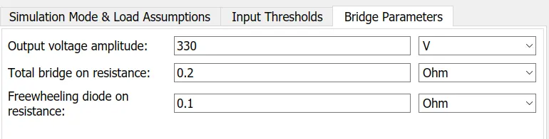
Output Voltage Amplitude of the H-Bridge circuit is given the same value as the rated DC supply Voltage of the DC motor.
Controlled PWM Voltage block
Simulink provides an inbuilt Controlled PWM Voltage block. This block is used for providing the proper pulse input to the block
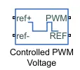
The Controlled PWM Voltage block represents a pulse-width modulated (PWM) voltage source.
-
Electrical input ports — The block calculates the duty cycle based on the reference voltage across its ref+ and ref- ports. This modeling variant is the default.
-
PS input — Specify the duty cycle value directly by using an input physical signal port.
The PWM and REF connection are for the corresponding ports on the H-Bridge Circuit.The two reference inputs corresponds to the throttle inputs given by the driver.The block generates corresponding pulse width as per the acceleration and brakes applied by the driver himself.Here the PWM frquency is 4000Hz. Also the simulation mode is Averaged as that in the H-Bridge circuit.
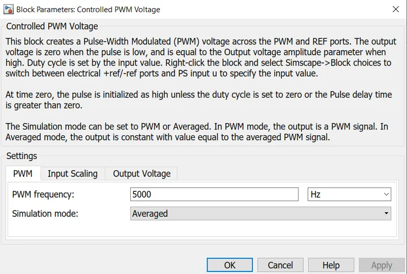
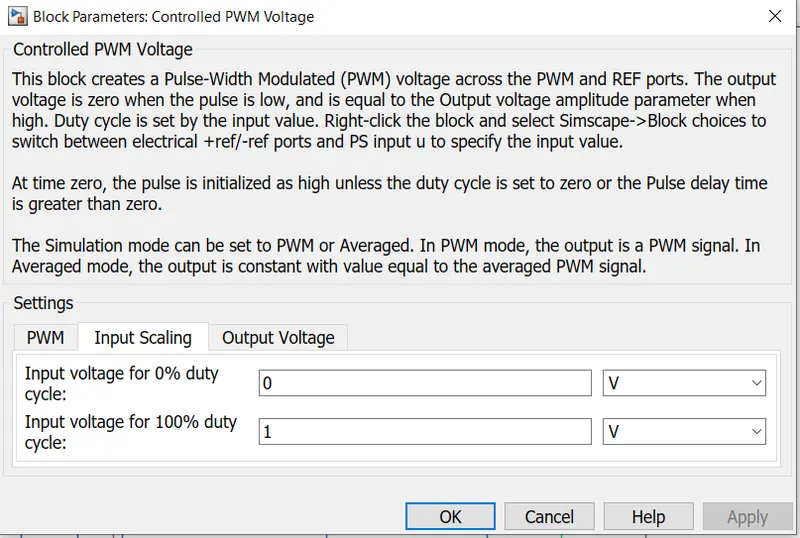
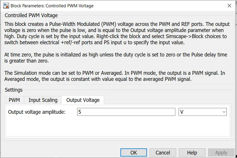
The input Scaling Parameters given are
- 0V for 0% duty cycle and 5V for 100% duty cycle. So the output voltage amplitudes becomes 5V.
The H-Bridge circuit along with the PWM input, together form the motor controller circuit.
Motor and controller
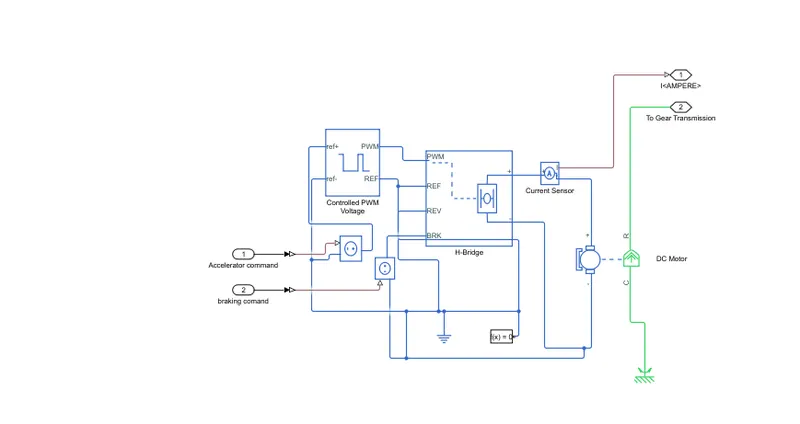
Lithium ion battery with an controlled current source conected to it in which it is fed by the current that is being measured by the current sensor at H-bridge to DC motor connection
subsystem of controller
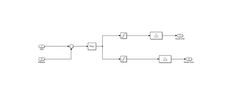
the PI controller is fed from the Drive cycle source as velocity reference and vehicle speed as the feedback both where summed to produce error signal and that is fed to the PI controller two saturation blocks with 1,0 for acceleration command and 0,-1 for brake command as well as the transfer functions for an idealistic plants for non linear compensation so this can produce the accelearation command aand brake command which directly fed to the pwm generator and brake port of the H-bridge
Results:
let us see the simulated results for simulink run time 2474s
Velocity reference and the vehicle vleocity
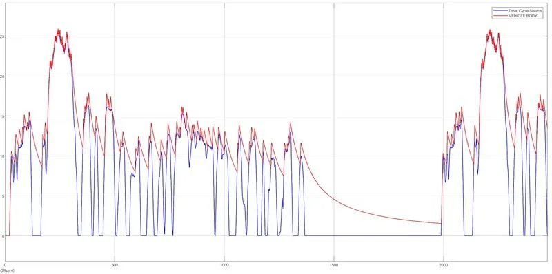
we can see the blu one as velocity reference from drive cycle source and the red one is vehicle velocity in which it almost synced to it but when deceleration or brake command is applied, it is applying only to the motor which is called electrical braking if mechanical braking is also added to the vehicle body which synchronised with the brake command the velocity reference from the drive cycle source and vehicle velocity got synced 100%.
let us see the battery current and soc%
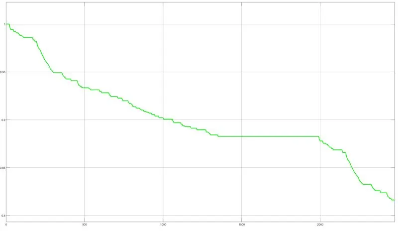
we are seeing the soc % in which it dropped from 100% to neaarly 81% which is meant that battery consumed 19% for the distance of 7.495miles
let us see the battery current
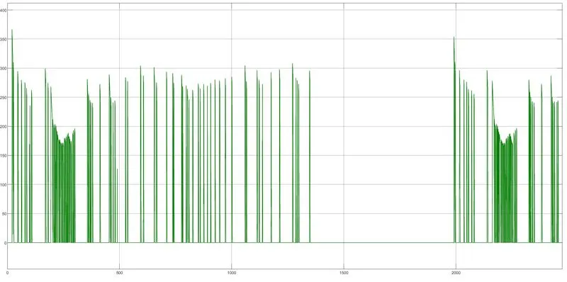
we are seeing so many spikes during the acceleration and a compleate drop during the deceleration
Conclusion:
An electric car with suitable motor and lithium battery with an PI controller is designed in SIMULINK, and also simulated with standard drive cycle as a velocity reference for PI controller in which we acheived the electrical braking and the vehicle velocity synced almost 70% to the velocity reference because of the capacity of the motor it immediently accelerating as the dc motor has the high torque so if we apply mechanical brakes synchronisig with the PI controller we can achieve 100% sync with the velocity reference.