Project-1: Modelling an electric Car with Li-ion battery
Question:
Create a MATLAB model of electric car which uses lithium ion battery and suitable motor. Choose suitable blocks from Simscape or Powertrain block set. Implement the vehicle speed control using PI controller and generate brake and accelerator commands. Avoid using readymade driver block for speed control.
Prepare a report about your model including following:
Objectives, System level configurations, Model parameters, Results, Conclusion.
(Note- The simulink model file should be compulsorily attached)
About Lithium-ion batteries:
This are one of the most widely used types of rechargeable battery, and their dominance continues to grow year-over-year. Here a brief overview of a technology that has transcended generations in technology.
In the 1970s a team of research scientists began working on what would become the lithium-ion (Li-ion) battery, a type of rechargeable battery that would one day power pretty much everything. From portable electronics to electric vehicles, it's a technology that has well and truly shaped the electronics industry and our world.
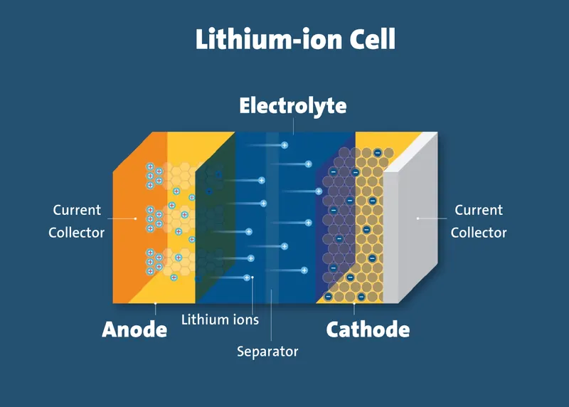
we can seefrom the below figure the four components of a typical Li-ion battery. On the right is the anode and on the right is the cathode (the positive terminal). These are kept apart by a porous separator and an electrolyt
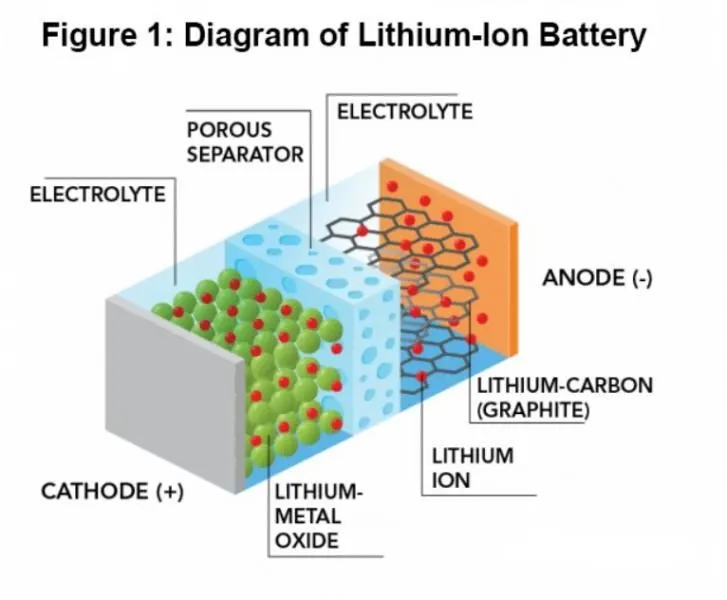
In the normal operation of a Li-ion battery, positively charged lithium ions (Li+ ions) flow from the anode to the cathode through the porous separator. A corresponding electron current flows through the electrical load from the anode to the cathode. Lithium is used because it's the cheapest, lightest, and most abundant electropositive chemical element.
It is simple a technology has proven to be totally transformational. Without it it's likely that the digital revolution that we've seen over the last few decades with portable devices leading the way would not have occurred. In addition, the major progress we're seeing with electric vehicles would have struggled to take off.
Given that the fundamental structure of the Li-ion battery is the same as that of Alessandro Volta who described and invented the first battery -composed of copper and zinc stacks separated by saltwater-in 1800 the levels of innovation and progress that we've seen and continue to see is staggering.
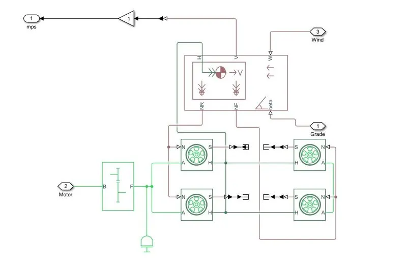
Tire:
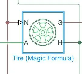
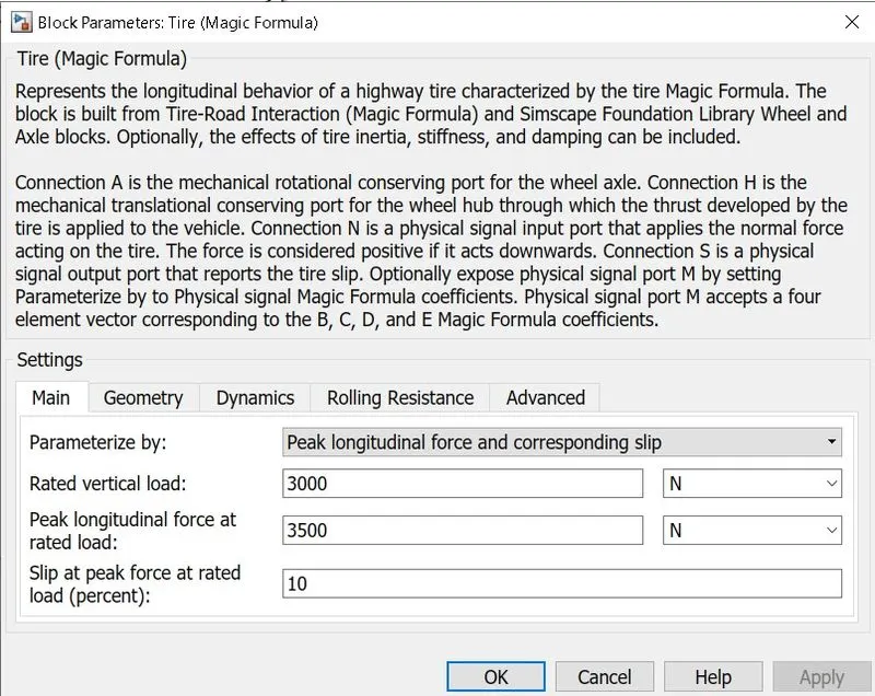
A-axles: This port is a mechincal rotational port which is associated with the axle that the tire sits on it
S-slip: This port is physical siginal outport which is associated with the
relative slip between the tire and road
H-hub: This port is a mechincal translational port which is associated with the wheel hub which transmits the torque generated by the tire to the remaning of the vehicle
N - Normal reaction: This port is a physical input port which is
associated with the normal force acting on the tire
The normal froce is positive when it acts downward on the tire pressing it against the pavement this tires are connected to the vehicle body
Vehicle body:
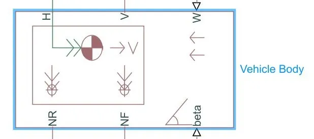
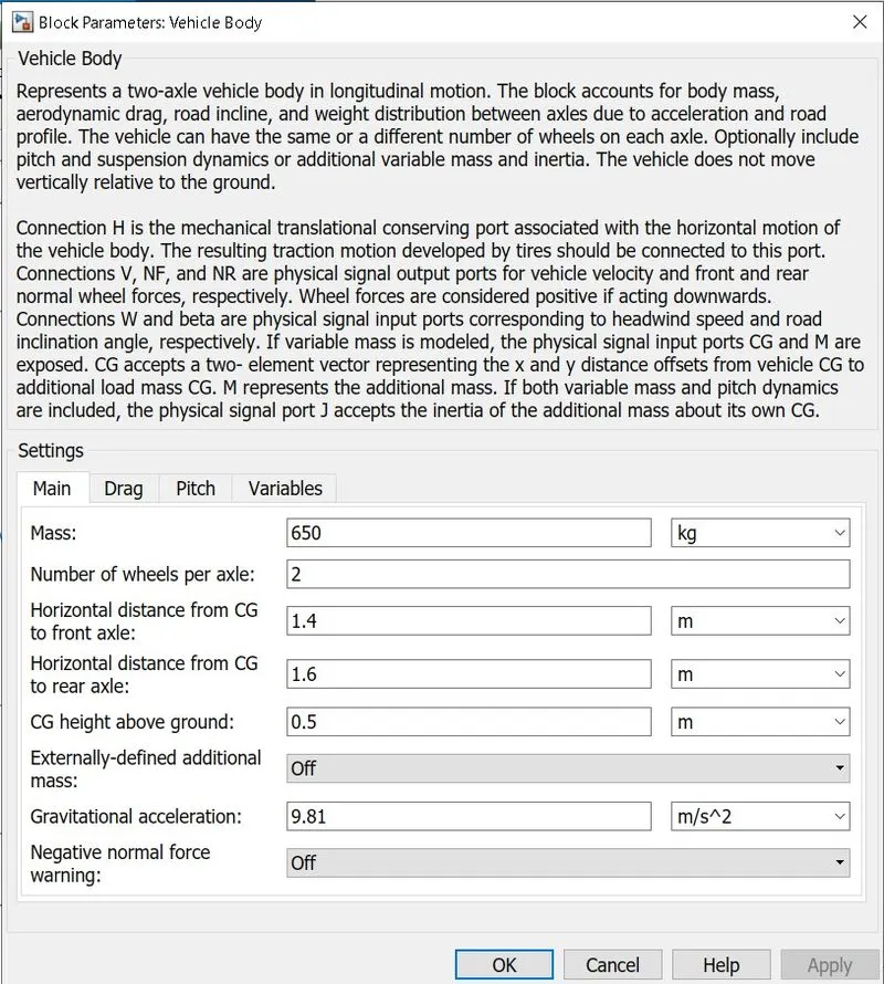
- Here NR-normal reaction. This port is physical siginal output port for the normal force on the rear axle wheel force are considering postive if it acting as downwards
- NF- normal force front, This port is physical siginal output port for th
normal reactions force on the front axle when wheels force are
considered postive if acting downwards
- H-horizontal motion, This port is conserving port which is associated
with the horizontal motion of the vehicle body which connects tire
traction motion to this port
- V-longitudinal velocity.This port is speed of the vehicle body
- Beta Road incline angle This port is used for the grade of the vehicle
Simple gear:
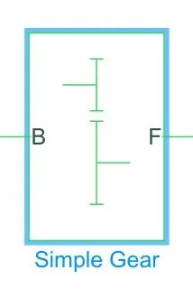
Simple Gear is a Final drive ratio which is a gearbox that constrains the connected driveline axes of the base gear and the follower gear.
B: The output B, base gear is connected with the input of DC motor R. It is a Rotational mechanical conserving port.
F: The output of F, follower gear is connected with the rear axle. It is also a Rotational mechanical conserving port.
In Simple Gear Block we can also do some changes according to our need.
Main setting
Follower (F) to base (B) teeth ratio (NF/NB): 2, The value should be in Positive and it is a fixed ratio gFB of the follower gear to the base gear.
Output shaft rotates: In the same direction as the input shaft, it is depending upon the direction of follower and base gear.
Meshing Losses
Friction model: From drop-down, we can select Constant efficiency which calculates the Reduce torque transfer by a constant efficiency factor.
Efficiency: 0.86, here we can change the efficiency depending upon our need, basically it is a Torque transfer efficiency between base gear shaft to the follower gear shaft.
Follower power threshold: 0.001 W, it is an absolute value of the follower shaft power above which the full efficiency factor is in effect.
Inertia:
The block represents an ideal mechanical rotational inertia.
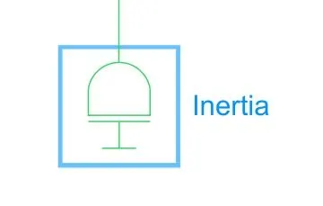
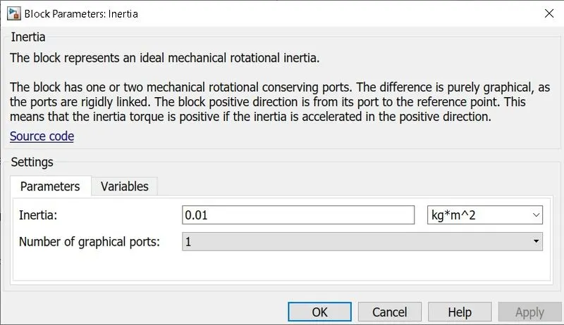
The block has one or two mechanical rotational conserving ports. The difference is purely graphical, as the ports are rigidly linked. The block positive direction is from its port to the reference point. This means that the inertia torque is positive if the inertia is accelerated in the positive direction.
Battery:
SOC battery
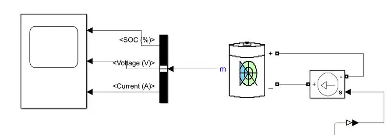
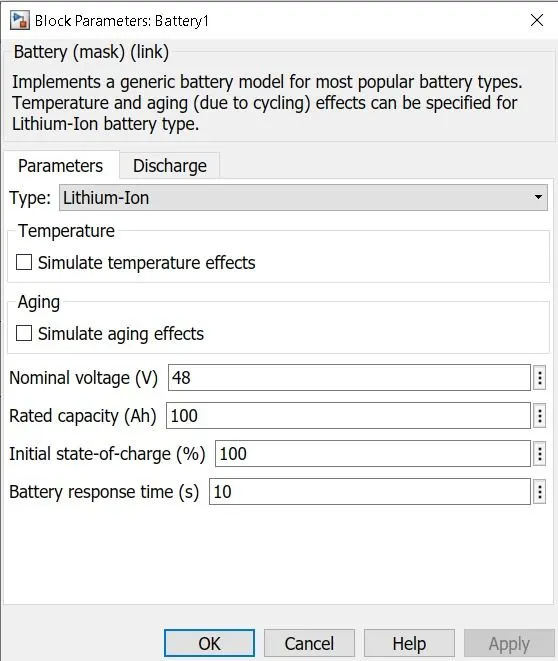
- Here if we select the infinite of the battery charge capacity paramter the block changes as the battery as a series resistor and constant voltage source
- I when we select the finite for the battery charge capacity then the
- block changes to battery as a series resistor and a charge dependent voltage source
- The connection of the battery is the negative terminal is connected to the ground and then it controls the current source physical port to
- the postive port direction which aslo indicates the flow of the current
- The postive terminal is then connected to the controlled current source of the electrical conserving ports
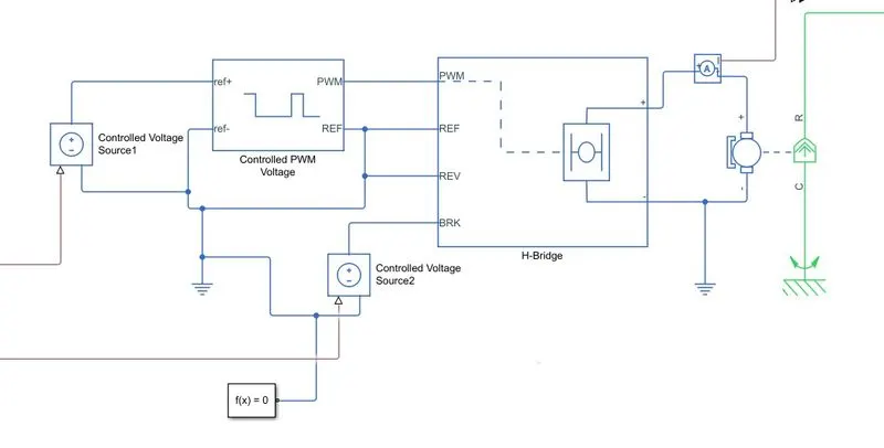
Motor controlled control system:
DC motor:
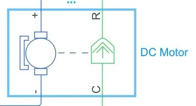
- The DC Motor block represents the electrical and torque characteristics of a DC motor using the following equivalent circuit model:
- Here in this system, the positive terminal is connected with the current sensor negative terminal and negative terminal is connected with the negative terminal of H-Bridge.
- R is DC motor rotor which connected with mechanical rotational port i.e. simple gear whereas C is DC motor case and it is connected with mechanical rotational reference.
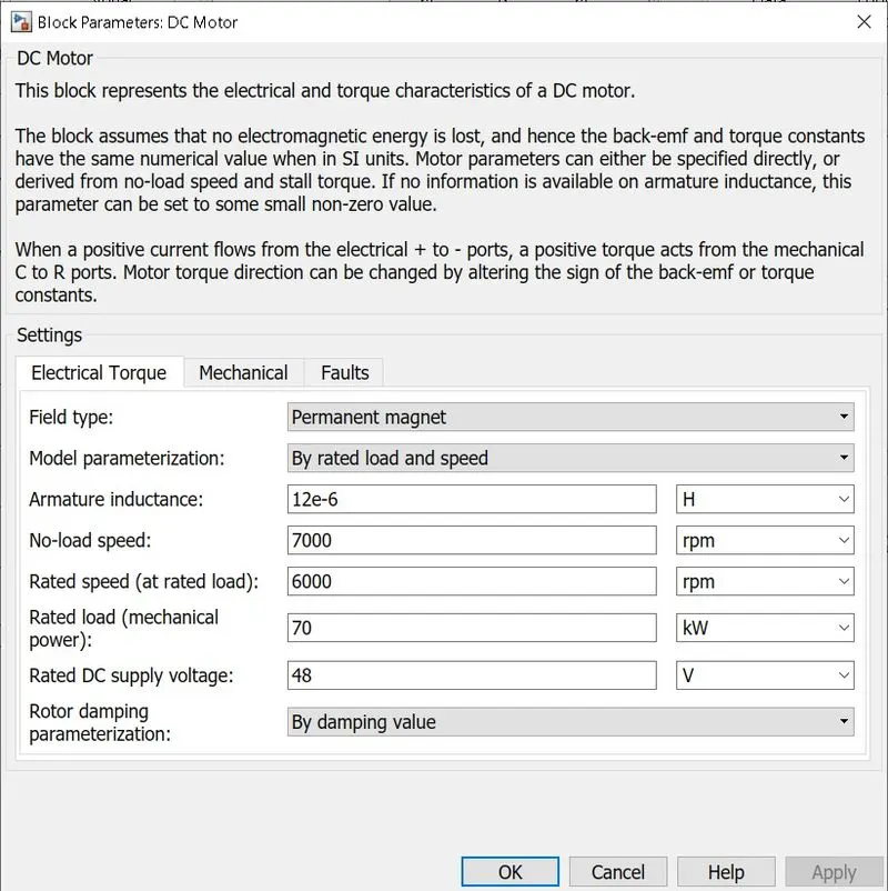
- A basic configuration of the DC motor is as follow:
- Here for the particular model, I configure in DC Motor and try to change a basic setting in electrical torque.
- No-load Speed: 8000 rpm, this is the speed of the motor when not driving a load.
- Rated speed (at load): 5000 rpm, this is the speed of the motor at rated mechanical power level.
- Another Mechanical detail of DC motor is as follow
- Rotor Inertia: It’s a resistance of the rotor to change in motor motion.
- Rotor Damping: It should be zero because it is energy dissipated by the motor.
- Initial Rotor Speed: This is a starting speed of the motor that at what speed the motor will start.
H-Bridge:
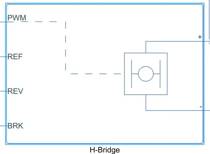
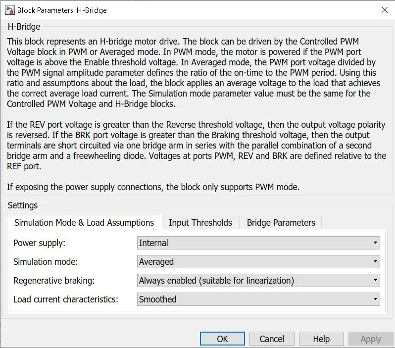
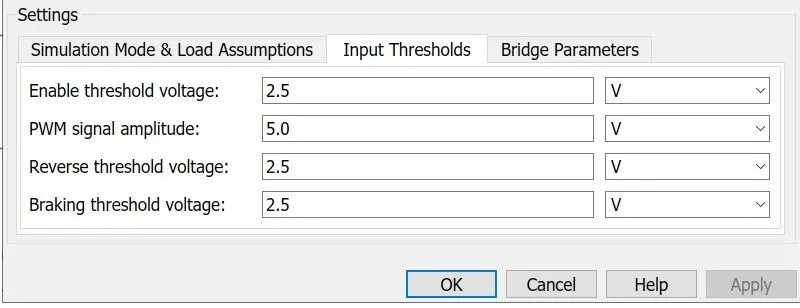
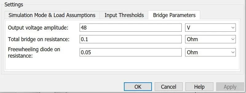
- It mainly consist of 2 ports the left side id for controlling of the
- voltage siginals and the right side for the terminals to provide the
- controlled voltage of the Dc motor
- The left side ports of H bridge are
- PWM: This a pulse width modulation which will provide the voltage pulses to the H bridge either in the PWM or average mode
- REF: this a reference port
- REV this is reverse port
- BRK:this is a brake port
- Here the PWm ourput is connected with the PWM input of controlled PWM voltage
- The REF and REV port are connected with REF port of the controlled PWM voltage port
- The BRK port is connected with the controlled volatge source
- It mainly shows that the postive terminal is connected to the postive of the current sensor and negative is connected with the negative of the DC motor
Controlled PWM voltage:
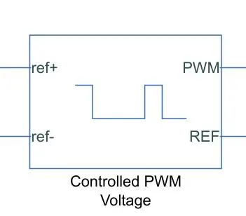
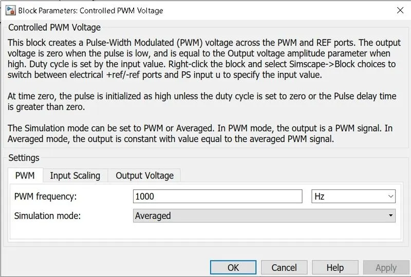
- Here Ref+: is the postive electrical reference voltage
- Ref-: is the negtive electrical reference voltage
- PWm: is the electrical conserving port which is associated with thepwm siginal
- REF: is the conserving port which is associated with the floating zero volt
- The value of the output voltage amplitude paramter gives amplitude of the output voltage
Controlled voltage source:
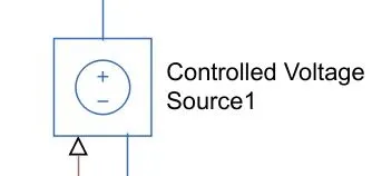
The block represents an ideal voltage source that is powerful enough to maintain the specified voltage at its output regardless of the current passing through it. The output voltage is V = Vs, where Vs is the numerical value presented at the physical signal port.
Solver configuration:
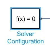
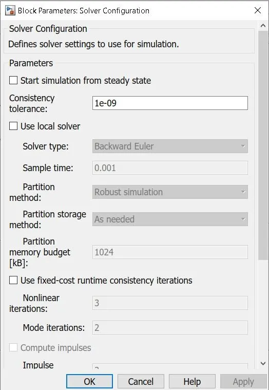
Defines solver settings to use for simulation.
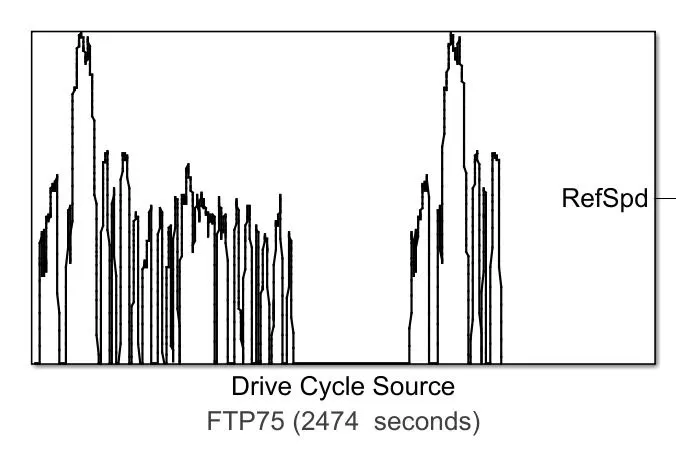
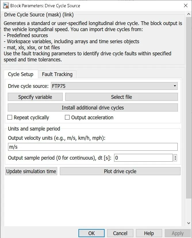
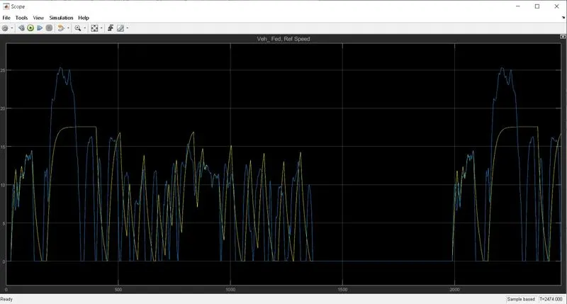
- Here the connection of drive cycle Refspeed is connected with the VelRef of longitudinal driver and then to the scope results which generates vehicle reference speed
- The block output is specified by the vehicle longitudinal speed which we can use to perdict the engine torque and fuel consumption which requires to the achiev desired speed and acceleration
- It aslo produces the realstic velocity and shift reference for the closed loop acceleration and braking commands for the vehicle control and plant model
- Here study and tune and optimize vegicle control system performance and system robustness over mutliple drive cycles
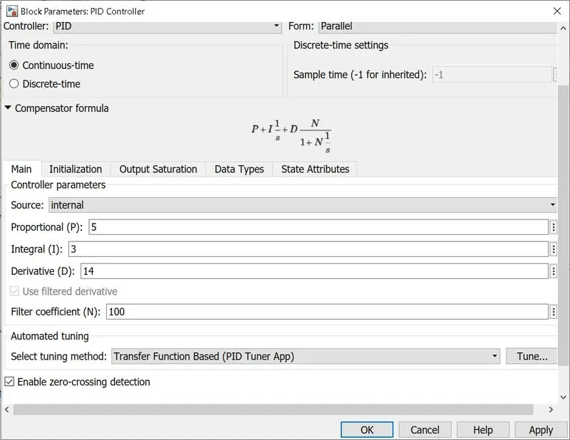
PID block:
Accelaration and decceleration:
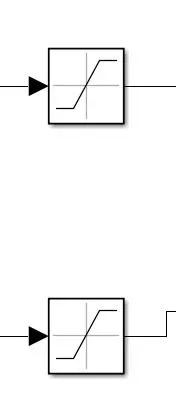
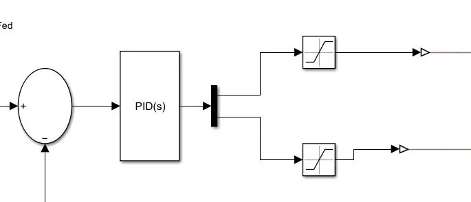
- Here upper limit specifies the upper bound on the input siginal
- when the input siginal to the saturation block is shown in above value the output block is clipped to this value
- Lower limit specifies the lower bound on the input siginal
when the input siginal to the saturatin block is below this value the - output of the block is clipped to this value
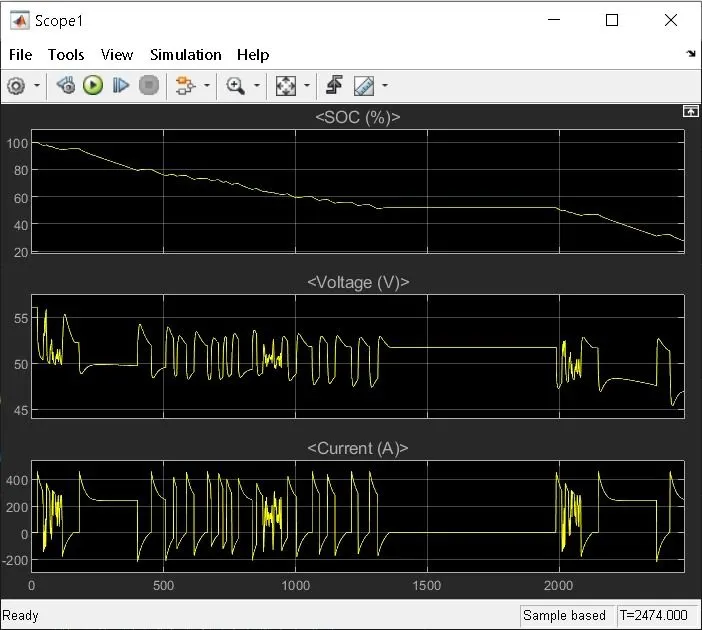
Output:
Conclusion:
we have Created a MATLAB model of electric car which using lithium ion battery and with suitable motor. and also suitable blocks from Simscape or Powertrain block set. Implemented the vehicle speed control using PI controller and generated brake and accelerator commands. BY Avoiding the use of readymade driver block for speed control.
Prepared a report about the model including following:
Objectives, System level configurations, Model parameters, Results.