Project-1: Modelling an electric Car with Li-ion battery
Create a MATLAB model of electric car which uses lithium ion battery and suitable motor. Choose suitable blocks from Simscape or Powertrain block set. Implement the vehicle speed control using PI controller and generate brake and accelerator commands. Avoid using readymade driver block for speed control.
Project-1: Modelling an electric Car with Li-ion battery
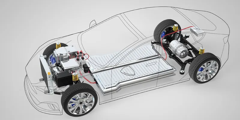
Electric Car Components and their functions
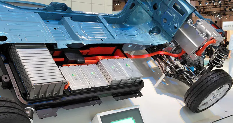
Electric car or vehicle component and function depend on the car type. There are at least four types of electric cars (Please read the article “Types of Electric Cars, Architecture and Working Principles“) currently sold commercially and operates in the world. This article will discuss various common main electric car components or parts or elements and their function such as traction batteries, inverters (DC-DC converters), traction motors, on-board chargers and controllers. The different types of electric car components determines how the car works. Electric cars (vehicles) components and functions can be explained by means of picture below.
Working Principles of BEV
- Power is converted from the DC battery to AC for the electric motor
- The accelerator pedal sends a signal to the controller which adjusts the vehicle’s speed by changing the frequency of the AC power from the inverter to the motor
- The motor connects and turns the wheels through a cog
- When the brakes are pressed or the electric car is decelerating, the motor becomes an alternator and produces power, which is sent back to the battery
When the car pedal is pressed, then:
- Controller [C] takes and regulates electrical energy from batteries [A] and inverters [B]
- With the controller set, the inverter then sends a certain amount of electrical energy to the motor (according to the depth of pressure on the pedal)
- Electric motor [D] converts electrical energy into mechanical energy (rotation)
- Rotation of the motor rotor rotates the transmission so the wheels turn and then the car moves.
Note: The working principle above is for battery electric vehicle (BEV) type.
Electric Vehicle Components
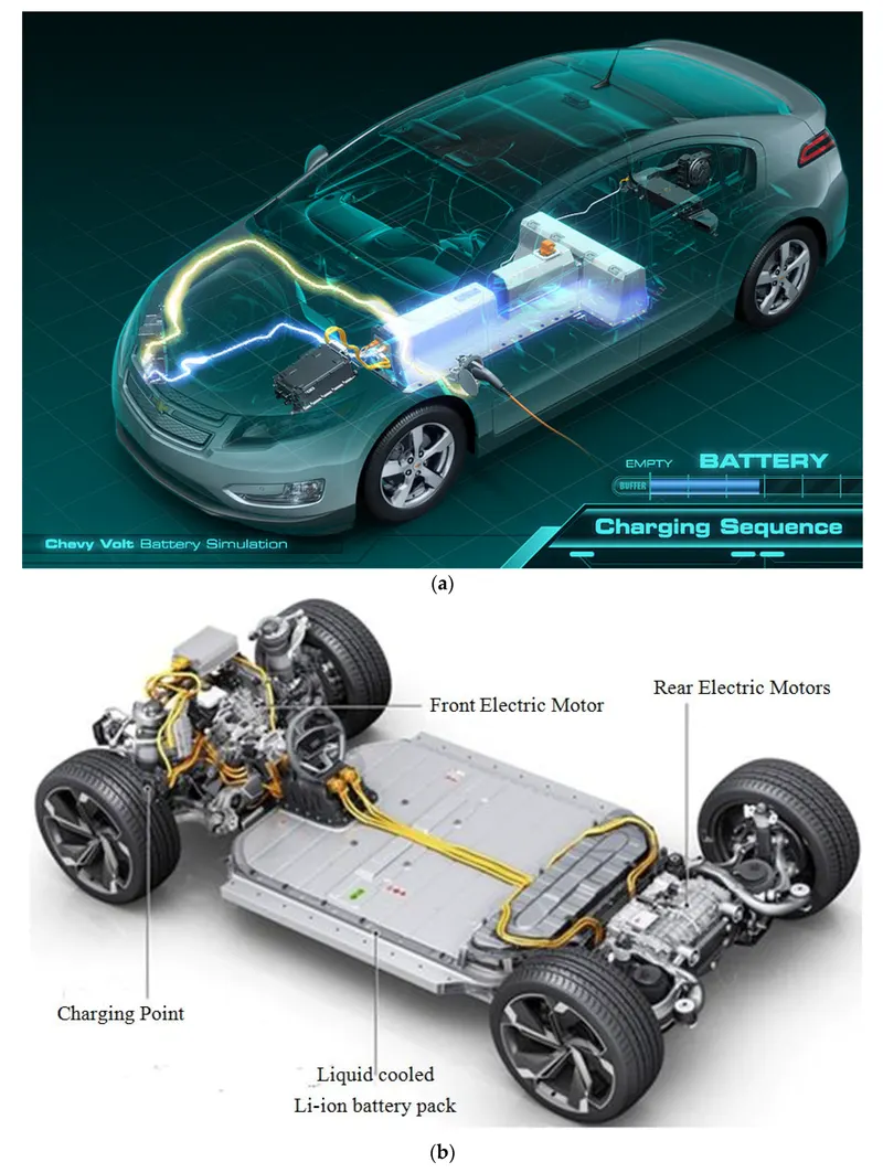
Basic Main Components of Electrical Vehicle
The basic main elements of electric cars installed in almost all types of electric cars are as follows:
Traction Battery Pack (A)
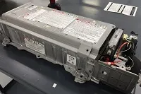
The function of the battery in an electric car is as an electrical energy storage system in the form of direct-current electricity (DC). If it gets a signal from the controller, the battery will flow DC electrical energy to the inverter to then be used to drive the motor. The type of battery used is a rechargeable battery that is arranged in such a way as to form what is called a traction battery pack.
There are various types of electric car batteries. The most widely used is the type of lithium-ion batteries. Please read the article “Electric Car Batteries and Their Characteristics” to get a little idea about batteries for electric cars.
Power Inverter (B)
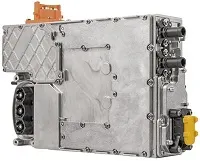
The inverter functions to change the direct current (DC) on the battery into an alternating current (AC) and then this alternating current is used by an electric motor. In addition, the inverter on an electric car also has a function to change the AC current when regenerative braking to DC current and then used to recharge the battery. The type of inverter used in some electric car models is the bi-directional inverter category.
Controller (C)
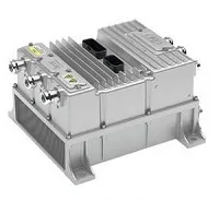
The main function of the controller is as a regulator of electrical energy from batteries and inverters that will be distributed to electric motors. While the controller itself gets the main input from the car pedal (which is set by the driver). This pedal setting will determine the frequency variation or voltage variation that will enter the motor, and at the same time determine the car’s speed.
In brief, this unit manages the flow of electrical energy delivered by the traction battery, controlling the speed of the electric traction motor and the torque it produces. This component will determine how electric car work.
Electric Traction Motor (D)
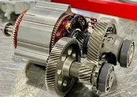
Because the controller provides electrical power from the traction battery, the electric traction motors will work turning the transmission and wheels. Some hybrid electric cars use a type of generator-motor that performs the functions of propulsion and regeneration. In general, the type of electric motor used is the BLDC (brushless DC) motor
———————————————
Other Electric Car Components
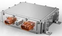
Charger (E) is a battery charging device. Chargers get electricity from outside sources, such as the utility grid or solar power plants. AC electricity is converted into DC electricity and then stored in the battery. There are 2 types of electric car chargers:
- On-board charger: the charger is located and installed in the car
- Off-board charger: the charger is not located or not installed in the car.
Transmission (F): The transmission transfers mechanical power from the electric traction motor to drive the wheels.
DC/DC Converter (G): This one of electric car parts that to converts higher-voltage DC power from the traction battery pack to the lower-voltage DC power needed to run vehicle accessories and recharge the auxiliary battery.
Battery (H): In an electric drive vehicle, the auxiliary battery provides electricity to power vehicle accessories.
Thermal System – Cooling (I): This system maintains a proper operating temperature range of the engine, electric motor, power electronics, and other components.
Charge Port (J): The charge port allows the vehicle to connect to an external power supply in order to charge the traction battery pack.
Types of Electric Cars
There are 4 (four) types of electric cars, with the following outline:
- Battery Electric Vehicle (BEV)
- Hybrid
- Hybrid Electric Vehicle (HEV)
- Plug-in Hybrid Electric Vehicle (PHEV)
- Fuel Cell Electric Vehicle (FCEV)
In brief, the system architecture of the four types of electric cars above can be seen in the following figure: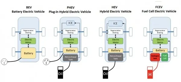
You can read more detailed explanation below.
———————————————
Battery Electric Vehicle (BEV)
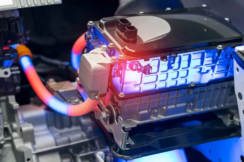
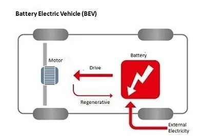
A Battery Electric Vehicle (BEV), also called All-Electric Vehicle (AEV), runs entirely on a battery and electric drive train. This types of electric cars do not have an ICE. Electricity is stored in a large battery pack that is charged by plugging into the electricity grid. The battery pack, in turn, provides power to one or more electric motors to run the electric car.
Architecture and Main Components of
 Components of BEV
- Electric motor
- Inverter
- Battery
- Control Module
- Drive train
Working Principles of BEV
- Power is converted from the DC battery to AC for the electric motor
- The accelerator pedal sends a signal to the controller which adjusts the vehicle’s speed by changing the frequency of the AC power from the inverter to the motor
- The motor connects and turns the wheels through a cog
- When the brakes are pressed or the electric car is decelerating, the motor becomes an alternator and produces power, which is sent back to the battery
Electric Car Batteries and Characteristics
Electric Car Batteries
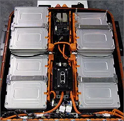
Electric car batteries are one of the most important components in a car system. In BEV cars, batteries are the only “life”. Because, only electrical energy stored in the battery is the only source of energy driving the BEV car. There are no other sources. The types of electric car batteries are also depends on the car system. The most popular electric car battery used is lithium-ion. Batteries that are considered zero emission abbreviated as ZEBRA. The most suitable battery for hybrid electric cars is NiMH. This article will explain at a glance about the different types of electric vehicle batteries and their characteristics along with a little about the Battery Management System (BMS)of an electric car.
Types of Electric Car Batteries
Electric car batteries are different from SLI batteries (starting, lightning and ignition). SLI batteries are batteries that are usually installed in gasoline or diesel cars. This type of electric cars battery is designed as an energy storage system, capable of delivering power for long and sustainable periods.
There are 5 types of electric vehicle batteries to be discussed in this article:
- Lithium-Ion (Li-On)
- Nickel-Metal Hybrid (NiMH)
- Lead Acid (SLA)
- Ultracapacitor
- ZEBRA (Zero Emissions Batteries Research Activity)
The comparison of the first four types of electric car batteries can be seen as follows: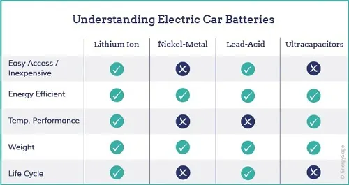
———————————————
Lithium-Ion Battery (Li-On)
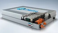 This type of electric vehicle battery is most widely applied is the Li-On battery. This battery may already be familiar to us because it is also used in many portable electronic equipment such as cellphones and laptops. The main difference is a matter of scale. Its physical capacity and size on electric cars is much greater – this is often referred to as a traction battery pack.
Li-on batteries have a very high power to weight ratio. This type of electric car battery is high energy efficiency. Performance at high temperatures is also good. The battery has a greater energy ratio per weight – a parameter that is very important for electric car batteries. The smaller the battery weight (same kWH capacity) means the car can travel further with a single charge.
This battery also has a low “self-discharge” level, so the battery is better than any other battery in maintaining its ability to hold its full charge.
In addition, most parts of Li-on batteries can be recycled, making it the right choice for those interested in environmentally conscious electric cars. BEV cars and PHEVs use the most lithium batteries.
Li-on battery Types
- Lithium Iron Phosphate(LiFePO4) — LFP
- Lithium Nickel Cobalt Aluminum Oxide (LiNiCoAlO2) — NCA
- Lithium Nickel Manganese Cobalt Oxide (LiNiMnCoO2) — NMC
- Lithium Titanate (Li2TiO3) — LTO
- Lithium Manganese Oxide (LiMn2O4) — LMO
- Lithium Cobalt Oxide(LiCoO2) — LCO
Li-ion battery parameters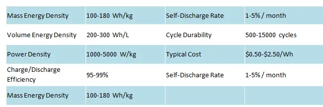
———————————————
Hybrid Nickel-Metal (NiMH) Batteries
 NiMH batteries are more widely used by hybrid-electric vehicles (HEV), but are also used successfully in some BEV cars. This type of hybrid electric car battery does not get power from outside (can be recharged from an outside source of the car system). The recharging of hybrid electric car batteries depends on engine speed, wheels and regenerative braking.
NiMH batteries have a longer life cycle than lithium-ion batteries or SLA batteries. NiMH batteries are safe and tolerant of incorrect usage. The biggest disadvantages of NiMH batteries include:
- The price is relatively more expensive
- High self-discharge rate
- Generate significant heat at high temperatures.
These deficiencies make NiMH less effective as a battery for electric cars whose batteries must be able to be recharged from outside the system, such as from the PLN network. That is why the car battery is the most widely applied by hybrid cars.
NiMH battery parameters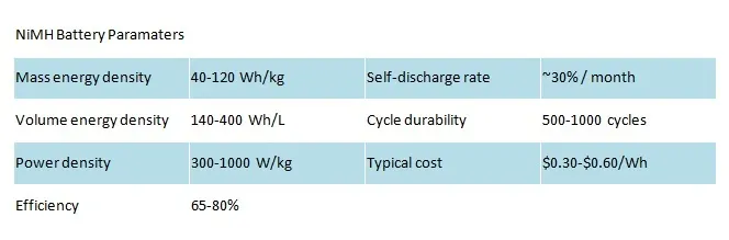
———————————————
Lead-Acid (SLA) Batteries
SLA (lead-acid) batteries are the oldest rechargeable batteries. Compared to lithium and NiMH batteries, lead-acid batteries do lose capacity and are much heavier, but the price is relatively cheap and safe. There are large capacity SLA electric car batteries under development, but SLA batteries are now only used by commercial vehicles as a secondary storage system.
Lead-acid battery parameters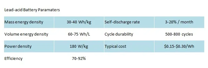
———————————————
Ultra-capacitor Batteries
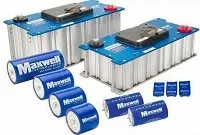 The ultra-capacitor battery is not like the general definition of a battery. In contrast to other electro-chemical batteries, this type of electric vehicle battery actually stores polarized liquid between the electrode and the electrolyte. As the surface area of the liquid increases, the energy storage capacity also increases. Like SLA batteries, ultra-capacitor batteries are very suitable as secondary storage devices in electric vehicles. This is because the ultra-capacitor helps electro-chemical batteries increase their load levels. In addition, ultra-capacitor can provide extra power to electric vehicles during acceleration and regenerative braking.
———————————————
ZEBRA Batteries
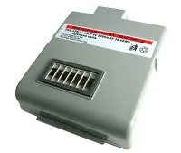 The battery for ZEBRA electric cars is a low-temperature variant of sodium-sulfur (NaS) batteries and is a development of ZEBRA (originally “Zeolite Battery Research Africa” then became a “Zero Emissions Batteries Research Activity” battery) in 1985. From the beginning ZEBRA batteries were indeed developed for electric vehicle applications. The battery uses NaAlCl4 with Na + -beta-alumina ceramic electrolyte.
Characteristics of ZEBRA batteries
- High power cell so that it fits as an electric car battery
- High temperature batteries operate at more than 270 ° C
- The chemical Sodium Nickel Chloride (NaNiCl) provides a nominal operating cell voltage of 2.58 Volts
Advantages of ZEBRA battery
- High energy density (5 times higher than SLA batteries)
- Large cells (up to 500Ah) allow
- Life cycle> 1000 cycles
- Short circuit tolerance
- Safer than Sodium Sulfur cells
- The typical cell failure is shorted but does not cause the battery to fully damage.
- Low cost ingredients
Disadvantages of ZEBRA battery
- Suitable for large capacity batteries (> 20KWh)
- Limited size and capacity range
- Only one factory in the world produces this battery.
- High internal resistance
- Liquid sodium electrode
- High operating temperature.
- Preheating is required to get the battery up to an operating temperature of 270 ° C (up to 24 hours from cold conditions)
- Uses 14% of its own capacity per day to maintain temperature when not in use.
- Thermal management is required
———————————————
Battery Management System
Battery management system or Battery Management systems (BMS) is a technology system that functions to maximize the life of electric vehicle battery and its characteristics. It is strongly recommended that all battery powered electric vehicles be installed BMS. The aim is to ensure the battery stays within the ideal working parameters. Some battery chemicals (such as lead acid) are quite tolerant of misuse, but lithium and NiMH can both be permanently damaged by a misuse such as over charging, over discharging, or overheating. All types of electric car batteries will benefit greatly by installing a BMS.
Some special functions of the battery management system include:
- Charge balancing, to ensure all cells complete charging at the same time then to prevent damage through overcharging.
- Active balancing, in which energy is transferred from stronger cells to weaker cells, to ensure all cells reach the maximum discharge point at the same time.
- Temperature monitoring (temperature monitoring), to avoid damage due to overheating.
- Low-voltage cut-off, a way to isolate a battery when any cell reaches the recommended minimum voltage, and to avoid damage due to overuse.
- State of charge (SOC) monitoring of all battery cells for electric cars. Through monitoring voltage and current, the remaining capacity of each cell can be calculated.
Modelling an electric Car with Li-ion battery
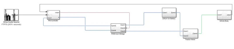
Components of simulink model are as follows:
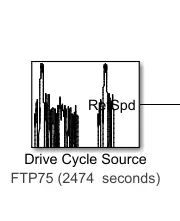
Description
The Drive Cycle Source block generates a standard or user-specified longitudinal drive cycle. The block output is the specified vehicle longitudinal speed, which you can use to:
-
Predict the engine torque and fuel consumption that a vehicle requires to achieve desired speed and acceleration for a given gear shift reference.
-
Produce realistic velocity and shift references for closed loop acceleration and braking commands for vehicle control and plant models.
-
Study, tune, and optimize vehicle control, system performance, and system robustness over multiple drive cycles.
-
Identify the faults within tolerances specified by standardized tests, including:
-
EPA dynamometer driving schedules1
-
Worldwide Harmonised Light Vehicle Test Procedure (WLTP) laboratory tests2
-
For the drive cycles, you can use:
-
Drive cycles from predefined sources. By default, the block includes the
FTP–75drive cycle. To install additional drive cycles from a support package, see Install Drive Cycle Data. The support package has drive cycles that include the gear shift schedules, for exampleJC08andCUEDC. -
Workspace variables that define your own drive cycles.
-
.
mat, .xls, .xlsx, or .txtfiles. -
Wide open throttle (WOT) parameters, including initial and nominal reference speed, deceleration start time, and final reference speed.
To achieve the goals listed in the table, use the specified Drive Cycle Source block parameter options.
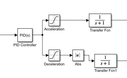
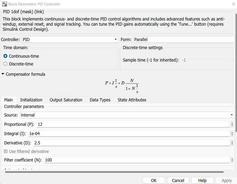
PID Controller block :
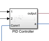
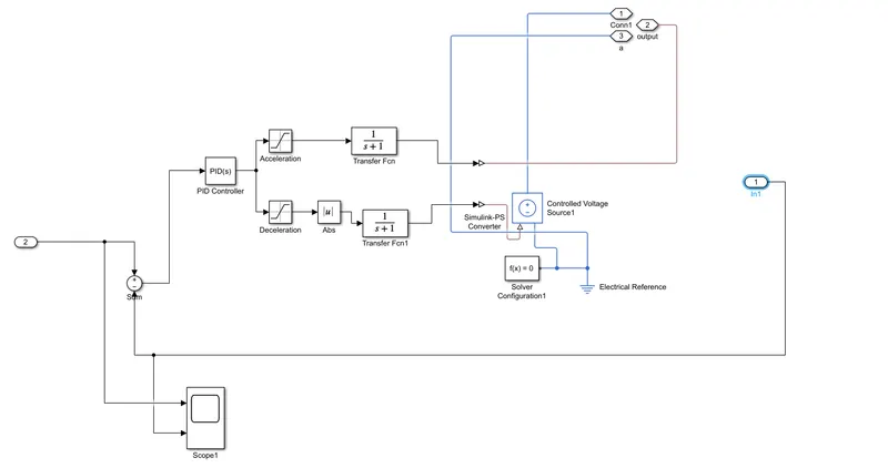
Explanation : We have used PID controller here instead of using longitudinal driver so as to control the vehicle performance .
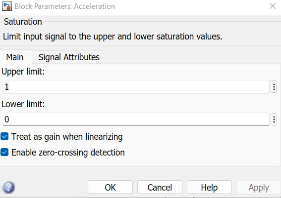
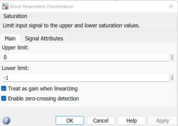
Connected two numbers of Saturation blocks so as to perform acceleration and de acceleration for the vehicle. By using Ps Simulink converter we connected both outputs of saturation to the voltage controlled pwm and H bridge.
PID Controller sub system :
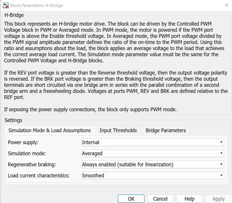
PWM and H Bridge
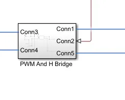
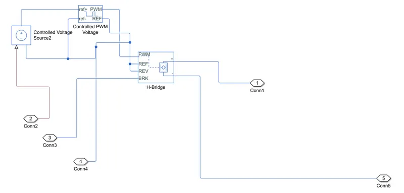

Discriptrion
The Controlled PWM Voltage block represents a pulse-width modulated (PWM) voltage source. The block has two modeling variants, accessible by right-clicking the block in your block diagram and then selecting the appropriate option from the context menu, under Simscape > Block choices:
-
Electrical input ports — The block calculates the duty cycle based on the reference voltage across its ref+ and ref- ports. This modeling variant is the default.
-
PS input — Specify the duty cycle value directly by using an input physical signal port.
-
-
Asynchronous – Best for variable-step solvers— Asynchronous events are better suited to variable step solvers, because they require fewer simulation steps for the same level of accuracy. In asynchronous mode the PWM switching events generate zero crossings, and therefore switching times are always determined accurately, regardless of the simulation maximum step size. -
Discrete—time – Best for fixed-step solvers— Discrete-time events are better suited to fixed-step operation, because then the switching events are always synchronized with the simulation step. Using an asynchronous implementation with fixed-step solvers may sometimes result in events being up to one simulation step late. For more information, see Simulating with Fixed Time Step — Local and Global Fixed-Step Solvers.
-
Simscape / Electrical / Semiconductors & Converters / Converters
-
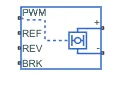
Discription
-
In PWM mode, the block has two options for the type of switching event when moving between output high and output low states:
The H-Bridge block represents an H-bridge motor driver. The block has the following two Simulation mode options:
-
PWM— The H-Bridge block output is a controlled voltage that depends on the input signal at the PWM port. If the input signal has a value greater than the Enable threshold voltage parameter value, the H-Bridge block output is on and has a value equal to the value of the Output voltage amplitude parameter. If it has a value less than the Enable threshold voltage parameter value, the block maintains the load circuit using one of the following three Freewheeling mode options:-
Via one semiconductor switch and one freewheeling diode -
Via two freewheeling diodes -
Via two semiconductor switches and one freewheeling diode
The first and third options are sometimes referred to as synchronous operation.
The signal at the REV port determines the polarity of the output. If the value of the signal at the REV port is less than the value of the Reverse threshold voltage parameter, the output has positive polarity; otherwise, it has negative polarity.
-
-
Averaged— This mode has two Load current characteristics options:-
Smoothed -
Unsmoothed or discontinuous
-
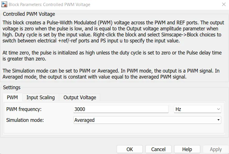
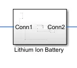
Lithium ion battey
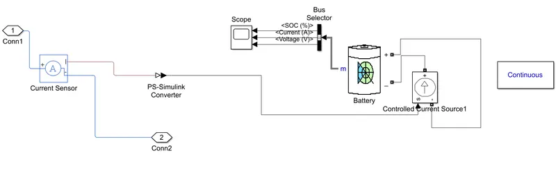
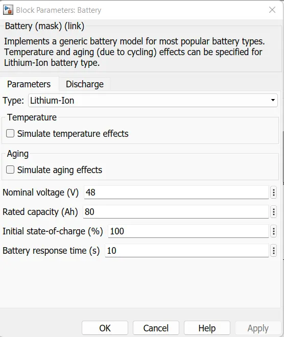
Here we have used Lithium ion battey with input parameters are as follows :Used scope for so as to obtain Battery SOC,current, Voltage . By using bus selector block.
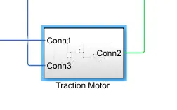
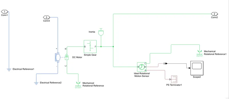
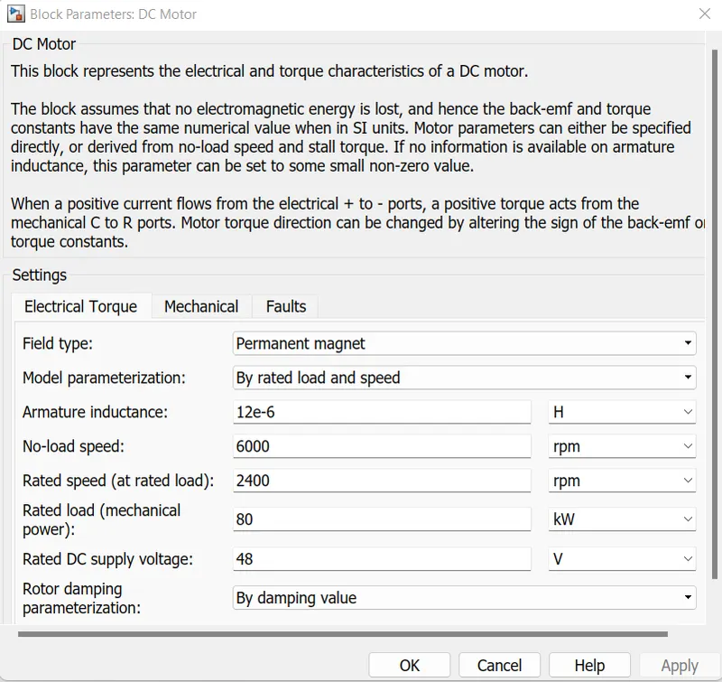
Traction Motor
Simple Gear
- ibrary:
-
Simscape / Driveline / Gears

Discription
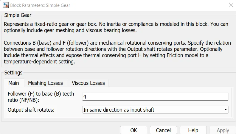
The Simple Gear block represents a gearbox that constrains the connected driveline axes of the base gear, B, and the follower gear, F, to corotate with a fixed ratio that you specify. You choose whether the follower axis rotates in the same or opposite direction as the base axis. If they rotate in the same direction, the angular velocity of the follower, ωF, and the angular velocity of the base, ωB, have the same sign. If they rotate in opposite directions, ωF and ωB have opposite signs.
Ideal Gear Constraint and Gear Ratio
The kinematic constraint that the Simple Gear block imposes on the two connected axes is
rFωF=rBωB
where:
-
rF is the radius of the follower gear.
-
ωF is the angular velocity of the follower gear.
-
rB is the radius of the base gear.
-
ωB is the angular velocity of the base gear.
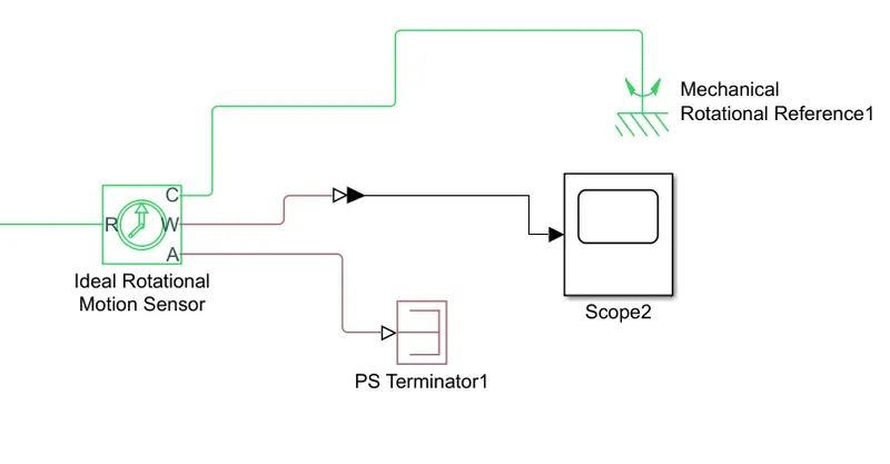
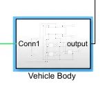
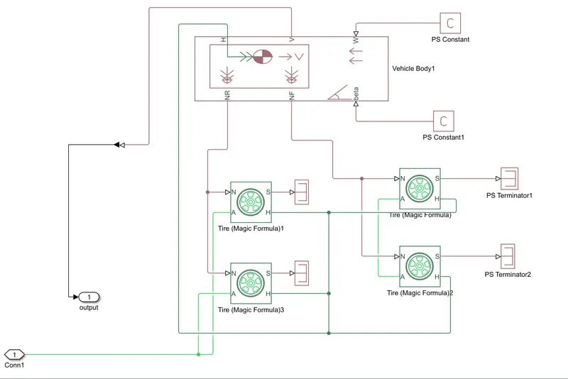
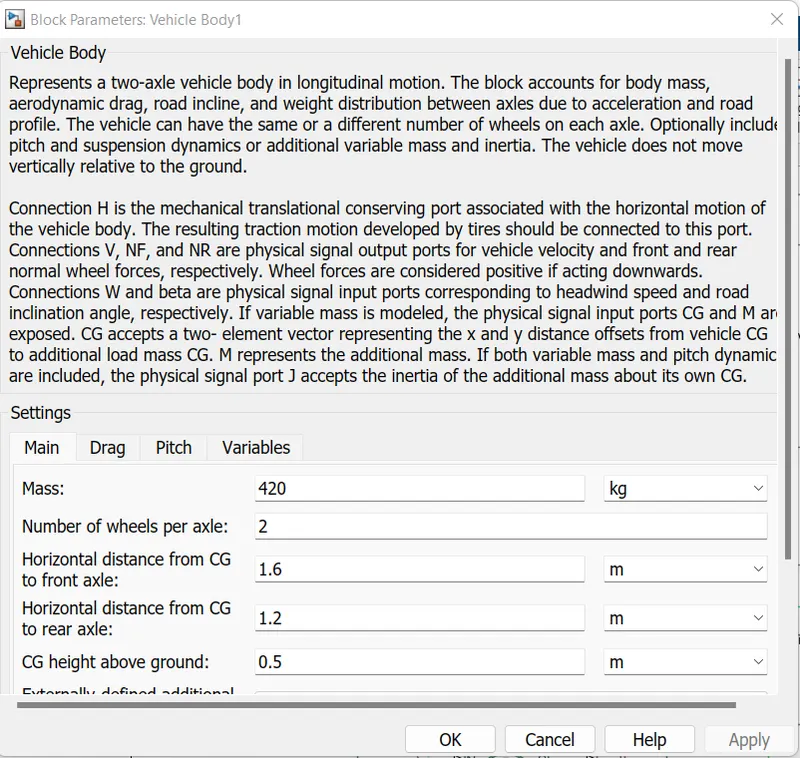
Vehicle body :
Results :
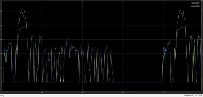
Scope 1
Vehicle drive cycle
Battery SOC
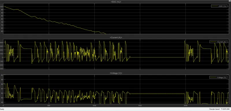
Conclusion : Battery SOC found decreasing as vehicle moves further , Soc is full at 100.
Current is varying it found stable in between values on x axis , 1400 to 1990 .
And Voltage is varying in nature as voltage increasing current decreasing vice vera.