Project-1: Modelling an electric Car with Li-ion battery
AIM:
Create a MATLAB model of electric car which uses lithium ion battery and suitable motor. Choose suitable blocks from Simscape or Powertrain block set. Implement the vehicle speed control using PI controller and generate brake and accelerator commands. Avoid using readymade driver block for speed control.
THEORY:
Plug-in electric vehicles (also known as electric cars or EVs) are connected, fun, and practical. They can reduce emissions and even save you money.
Fueling with electricity offers some advantages not available in conventional internal combustion engine vehicles. Because electric motors react quickly, EVs are very responsive and have very good torque. EVs are often more digitally connected than conventional vehicles, with many EV charging stations providing the option to control charging from a smartphone app.
Just like a smartphone, you can plug in your EV when you get home and have it ready for you to use the next morning. Since the electric grid is available almost anywhere, there are a variety of options for charging: at home, at work or on the road. By charging often, you may never need to go to a gas station again!
But EVs provide more than just individual benefits. EVs can help the United States have a greater diversity of fuel choices available for transportation. The U.S. used nearly nine billion barrels of petroleum last year, two-thirds of which went towards transportation. Our reliance on petroleum makes us vulnerable to price spikes and supply disruptions. EVs help reduce this threat because almost all U.S. electricity is produced from domestic sources, including coal, nuclear, natural gas, and renewable sources.
EVs can also reduce the emissions that contribute to climate change and smog, improving public health and reducing ecological damage. Charging your EV on renewable energy such as solar or wind minimizes these emissions even more. See the difference in emissions between a conventional vehicle and an EV using the calculator on the right. Learn more about how EVs reduce pollution and their lifecycle emissions.
Advantages of electric vehicles compared to internal combustion engine vehicles
Pure electric vehicles, also called battery electric vehicles (BEV), are the long term solution for mobility. Compared with internal combustion engine (ICE) powered vehicles, battery electric vehicles have a series of advantages which are summarised in the table below.
| Advantage | Electric vehicle | Internal combustion engine vehicle |
| Powertrain efficiency | Electric vehicles are powered by electric motors and single speed gearboxes which, depending on the operating point (speed and torque), have an overall efficiency between 75 … 95 %. This means that, for the same amount of power at the wheel, less energy is used from the high voltage battery compared with an internal combustion engine vehicle | The typical efficiency of an internal combustion engine is between 18 … 24 %. Diesel engine have slightly higher efficiency than gasoline engine but overall, internal combustion engines are 4 times less efficient than electric motors. Compared with an electric motor, for the same amount of wheel power, an internal combustion engine has to consume 4 times more energy |
| Vehicle acceleration | An permanent magnet synchronous electric motor has an ideal traction characteristic. Also, at zero speed, the electric motor can deliver the maximum available torque which translates in very good launch capabilities of the vehicle | An internal combustion engine can not deliver maximum torque from minimum speed (idle). They also need more time to reach maximum torque because of engine dynamics (air and mechanical inertia, turbo-lag, etc.) |
| Reliability | Having less moving parts, compared with an internal combustion engine, an electric motor has fewer sources of possible failures. Also, due to the high torque and high speed characteristic of the electric motor, there is no need for a multi-stage gearbox, a single-step mechanical gearbox is enough for propulsion | The internal combustion engine has many moving parts and also additional systems (fuel system, air induction system, exhaust gas after-treatment system, etc.) which can lead to possible failures. Due to the torque characteristic of the ICE, the vehicle requires a multi-step gearbox, which can also be a source of possible failures |
| Torque vectoring | For an all-wheel drive (AWD) electric vehicle, stability during cornering can be improved by controlling the torque at the wheels. Compared to the internal combustion engine, an electric motor has faster torque response and can also provide negative torque, which could prove essential in the stability of the vehicle | The internal combustion engine has limited contribution to the vehicle stability, most of the times, the electronic stability control system (ESC) it’s only reducing the amount of torque delivered by the engine |
| Total cost of ownership | Having less moving parts and components an electric vehicle is easier and cheaper to maintain. Also, the price of electric energy, in most of the countries, is less than fuel (petrol/gasoline or diesel). Moreover, since electric vehicles can perform regenerative braking, the main braking system of the vehicle has a lower usage factor which translates in longer service life | In order to preserve a good operating condition, internal combustion engines need regular maintenance (service) intervals for air filters, fuel filters replacement, spark plugs, oil change, etc.). For this reason a vehicle with internal combustion vehicle is more expensive to maintain compared with an electric vehicle |
| CO2 and exhaust gas emissions | Since there is no internal combustion engine present, electric vehicles have zero exhaust gas emission. Also, depending on the source of the electric energy (e.g. renewable) the overall CO2 impact of an electric vehicle is smaller compared with a internal combustion engine vehicle | Internal combustion engine vehicles are subject to legislative exhaust gas emission limits. Also, in some urban areas, they are forbidden to be driven. The general trend is to ban even further internal combustion engine vehicles in the highly dense populated urban areas |
PID CONTROLLER
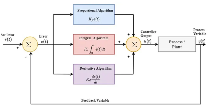
The proportional term
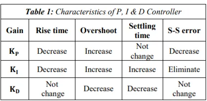
The proportional term produces an output value that is proportional to the current error value. The proportional response can be adjusted by multiplying the error by a constant Kp, called the proportional gain constant.
The proportional term is given by

A high proportional gain results in a large change in the output for a given change in the error. If the proportional gain is too high, the system can become unstable . In contrast, a small gain results in a small output response to a large input error, and a less responsive or less sensitive controller. If the proportional gain is too low, the control action may be too small when responding to system disturbances. Tuning theory and industrial practice indicate that the proportional term should contribute the bulk of the output change.
The integral term
The contribution from the integral term is proportional to both the magnitude of the error and the duration of the error. The integral in a PID controller is the sum of the instantaneous error over time and gives the accumulated offset that should have been corrected previously. The accumulated error is then multiplied by the integral gain (Ki) and added to the controller output.
The integral term is given by

The integral term accelerates the movement of the process towards setpoint and eliminates the residual steady-state error that occurs with a pure proportional controller. However, since the integral term responds to accumulated errors from the past, it can cause the present value to overshoot the setpoint value
The derivative term
The derivative of the process error is calculated by determining the slope of the error over time and multiplying this rate of change by the derivative gain Kd. The magnitude of the contribution of the derivative term to the overall control action is termed the derivative gain, Kd.
The derivative term is given by

Derivative action predicts system behavior and thus improves settling time and stability of the system. An ideal derivative is not causal, so that implementations of PID controllers include an additional low-pass filtering for the derivative term to limit the high-frequency gain and noise. Derivative action is seldom used in practice though – by one estimate in only 25% of deployed controllers because of its variable impact on system stability in real-world applications.
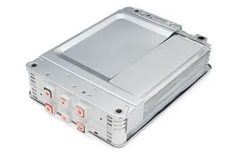
LITHIUM ION BATTERY
advantages:
High energy density - potential for yet higher capacities
Does not need prolonged priming when new. One regular charge is all that's needed.
Relatively low self-discharge - self-discharge is less than half that of nickel-based batteries
Low Maintenance - no periodic discharge is needed; there is no memory.
Specialty cells can provide very high current to applications such as power tools
disadvantages
Requires protection circuit to maintain voltage and current within safe limits.
Subject to aging, even if not in use - storage in a cool place at 40% charge reduces the aging effect.
Transportation restrictions - shipment of larger quantities may be subject to regulatory control. This restriction does not apply to personal carry-on batteries.
Expensive to manufacture - about 40 percent higher in cost than nickel-cadmium
BLOCK DIAGRAM:
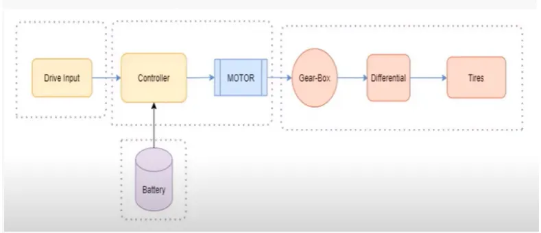
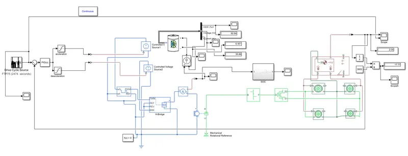
the model of electric vehicle is divided into four parts
1) vehicle body- in vehicle body we have gear box, tires, differential.
2) motor and controller part- we will use simple dc motor and H bridge controller.
3)drive input- we will create input by inbuilt drive cycle or by using signal builder block
4) battery
from the model we see that the drive input will provide driving cycle . the battery is connected to the motor through controller. if the battery is directly connected to motor , then controlling of speed is not possible.
the mechanical energy from dc motor is given to vehicle body so that the vehicle will perform accordingly.
MODEL:
BLOCKS USED IN MODEL:
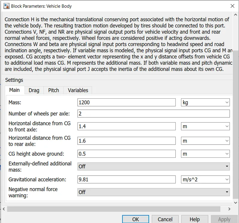
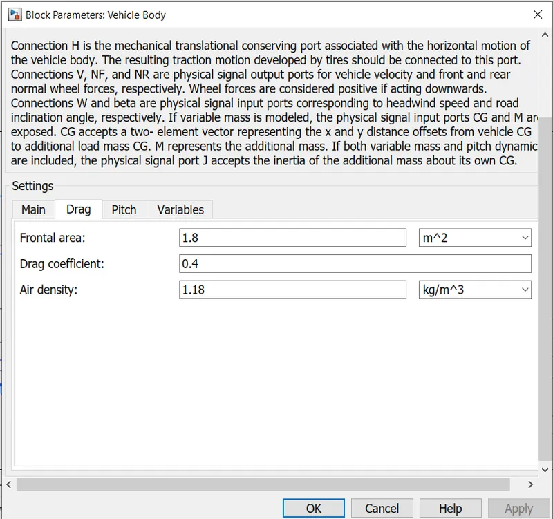
1) VEHICLE BODY
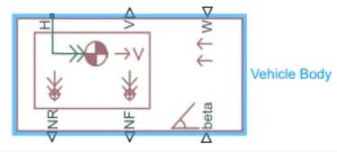
vehicle body have 6 ports.
V-actual sped of vehicle
w-wind velocity
beta- inclination of road
NF-normal force for front wheel
NR- normal force for rear wheel.
H-horizontal motion
2) TIRE:
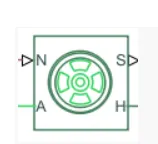
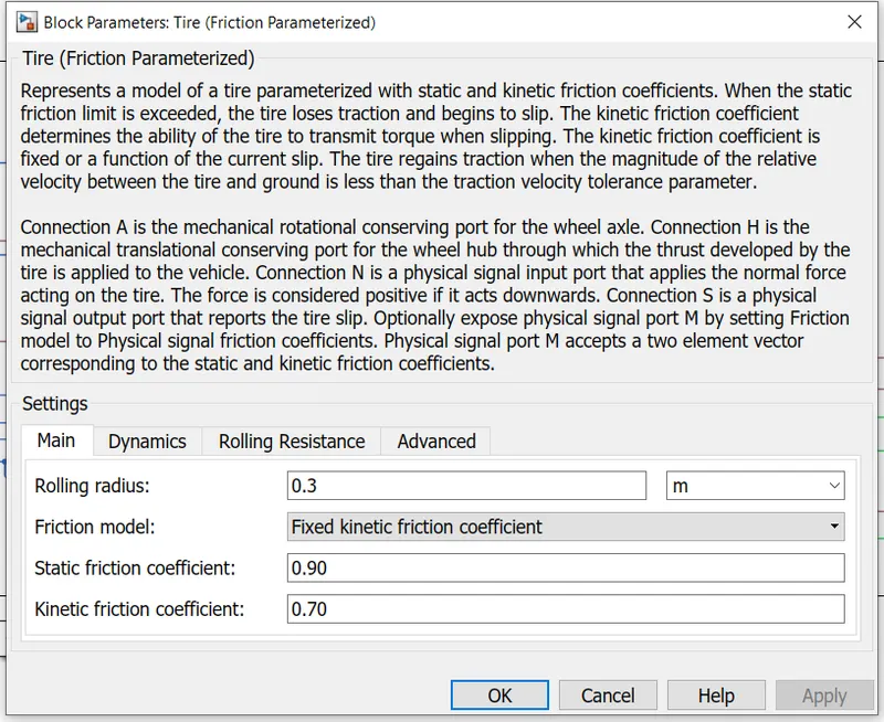
The Tire (Friction Parameterized) block models a tire with friction parameterized in terms of static and kinetic coefficients. The static friction coefficient determines the applied torque at which the tire loses traction and begins to slip. The kinetic friction coefficient determines the amount of torque that the tire transmits to the pavement once it begins to slip. The tire regains traction once its relative velocity over the pavement falls below the traction velocity tolerance specified.
To increase the fidelity of the tire model, the block enables you to specify properties such as tire compliance, inertia, and rolling resistance
input ports is
N-normal force
output port is
S-slip
conserving port are
1)A-axle
2)H-hub
3) DIFFERENTIAL:
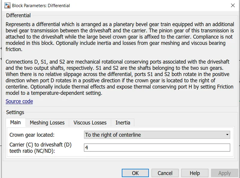
by diffrential block ,we can add inertia and losses of gear machine and viscous gear friction.
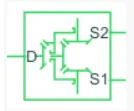
The Differential block represents a gear mechanism that allows the driven shafts to spin at different speeds. Differentials are common in automobiles, where they enable the various wheels to spin at different speeds while cornering. Ports D, S1, and S2 represent the longitudinal driving and the sun driven gear shafts of the differential.
the equivalent circuit for the block.
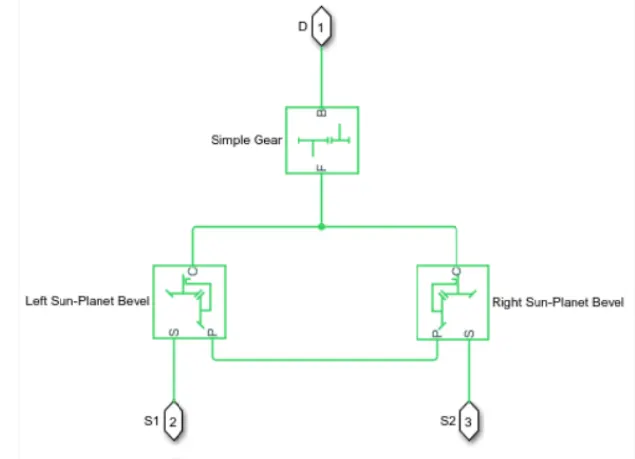
To increase the fidelity of the gear model, we specify the properties such as gear inertia, meshing losses, and viscous losses. By default, gear inertia and viscous losses are assumed negligible. The block enables us to specify the inertias of the gear carrier and internal planet gears only.
4) SIMPLE GEAR:
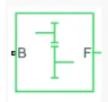
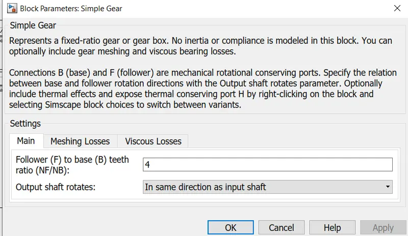
The Simple Gear block represents a gearbox that constrains the connected driveline axes of the base gear, B, and the follower gear, F, to corotate with a fixed ratio that we specify.
5) PS-SIMULINK CONVERTER-

vehicle body have physical quantities but the scope and display used show digital values .thus ps -simulink converter is used.
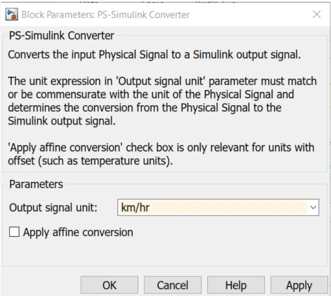
output signal unit is changed to km/hr
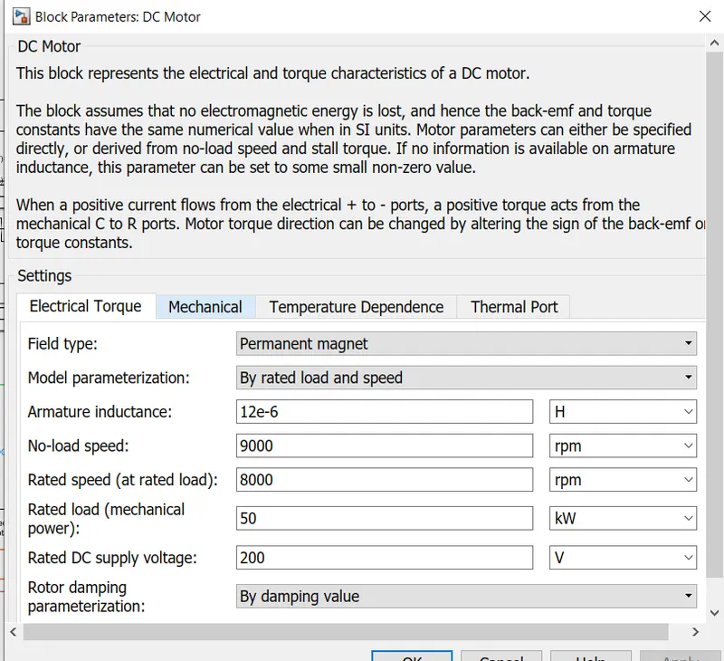
6) DC MOTOR:

+ = positive terminal
- = negative termional
c = motor case
R = motor rotor
the c terminal is connected to mechanical rotational reference.
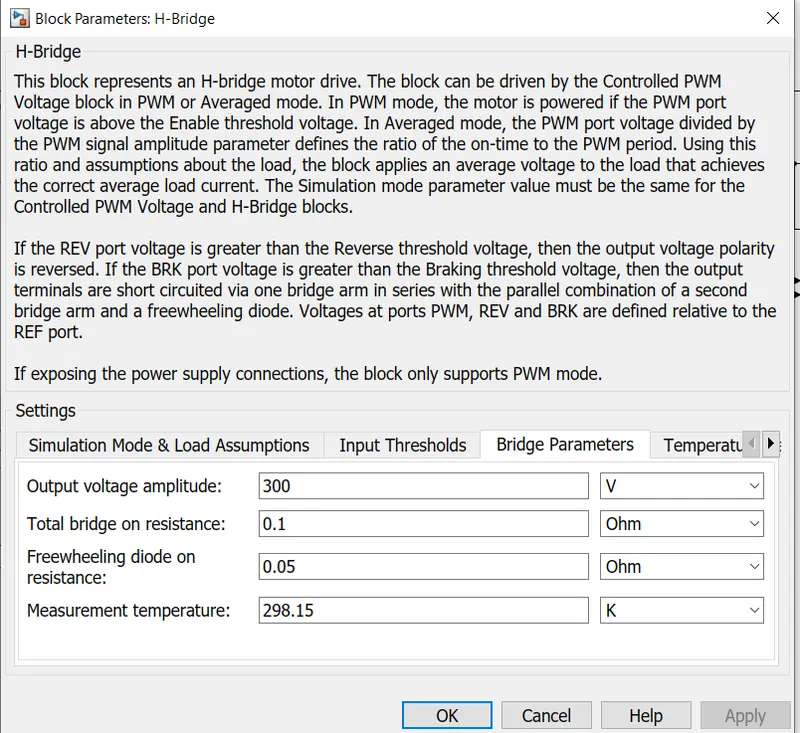
7) Hbridge coverter
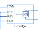
to control the motor current input , the H bridge converter is used.
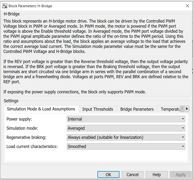
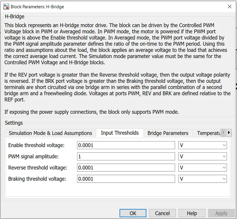
The H-Bridge block represents an H-bridge motor driver. The block has the following two Simulation mode options:
1)The H-Bridge block output is a controlled voltage that depends on the input signal at the PWM port. If the input signal has a value greater than the Enable threshold voltage parameter value, the H-Bridge block output is on and has a value equal to the value of the Output voltage amplitude parameter. If it has a value less than the Enable threshold voltage parameter value, the block maintains the load circuit using one of the following three Freewheeling mode options:
- via one semiconductor switch and one freewheeling diode
- via two freewheeling diode
- via two semiconductor switch and one freewheeling diode
The first and third options are sometimes referred to as synchronous operation.
2)The signal at the REV port determines the polarity of the output. If the value of the signal at the REV port is less than the value of the Reverse threshold voltage parameter, the output has positive polarity; otherwise, it has negative polarity.Electrical conserving port associated with the voltage that controls when to reverse the polarity of the H-Bridge block output. The voltage is defined relative to the REF port.
3)BRK PORT- Electrical conserving port associated with the voltage that controls when to short circuit the H-Bridge block output. The voltage is defined relative to the REF port.
by the help of h bridge we can perform accleration , braking and reverse mechanism.
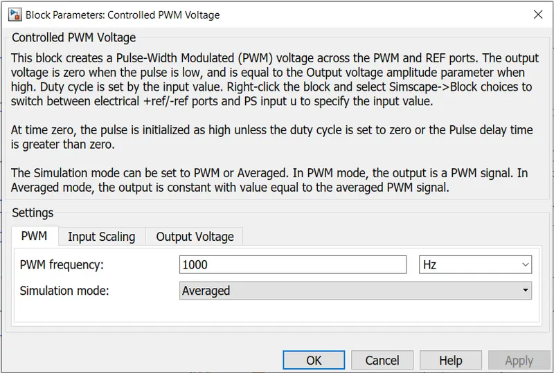
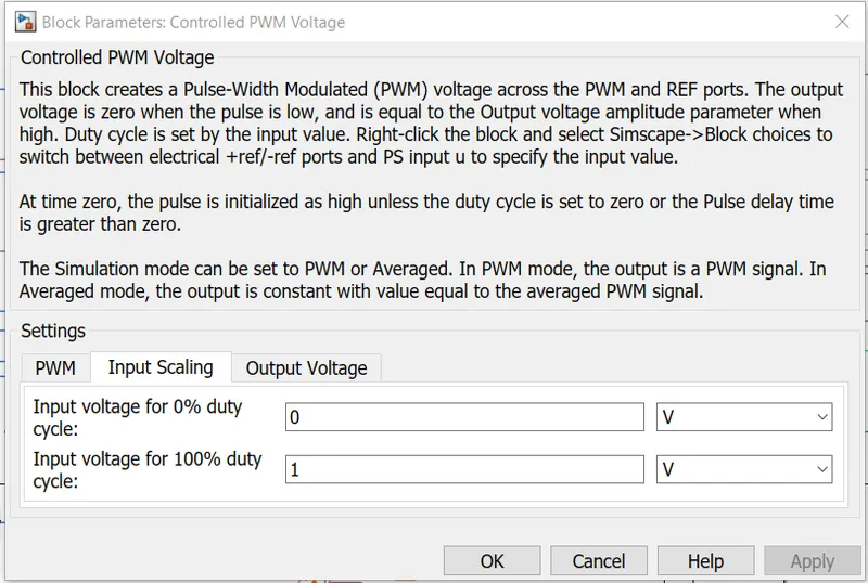
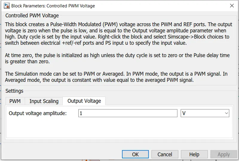
8) CONTROLLED PWM VOLTAGE:
to control PWm input we use controlled pwm voltage.
9) ELECTRICAL REFERENCE:

all the references are connected to electrical reference .also connect solver confugration to ground.
10) SIMULINK TO PS CONVERTER:

this block is used to convert simulink signal to physical signal.
11) CONTROLLED VOLTAGE SOURCE
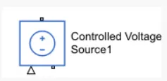
this block is used to provide constant voltage throughout the circuit.
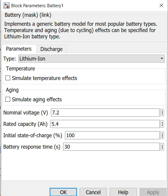
12) BATTERY

13)BUS SELECTOR
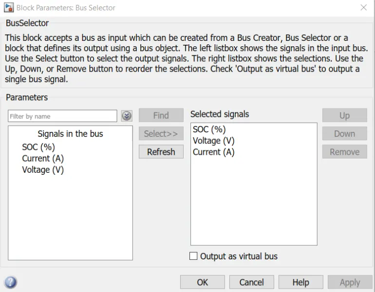
In bus selector, we have taken signal SOC , voltage and current.
14) CONTROLLED CURRENT SOURCE:

a controlled current source is connected to the lithium battery. this controlled current source will initiate the flow of current from battery to motor and during regenerative barking from motor to battery.
15) PID CONTROLLER

The PID Controller block implements a PID controller (PID, PI, PD, P only, or I only). The block is identical to the Discrete PID Controller block with the Time domain parameter set to Continuous-time.
The block output is a weighted sum of the input signal, the integral of the input signal, and the derivative of the input signal. The weights are the proportional, integral, and derivative gain parameters. A first-order pole filters the derivative action.
The block supports several controller types and structures. Configurable options in the block include:
-
Controller type (PID, PI, PD, P only, or I only) — See the Controller parameter.
-
Controller form (Parallel or Ideal) — See the Form parameter.
-
Time domain (continuous or discrete) — See the Time domain parameter.
-
Initial conditions and reset trigger — See the Source and External reset parameters.
-
Output saturation limits and built-in anti-windup mechanism — See the Limit output parameter.
-
Signal tracking for bumpless control transfer and multiloop control — See the Enable tracking mode parameter.
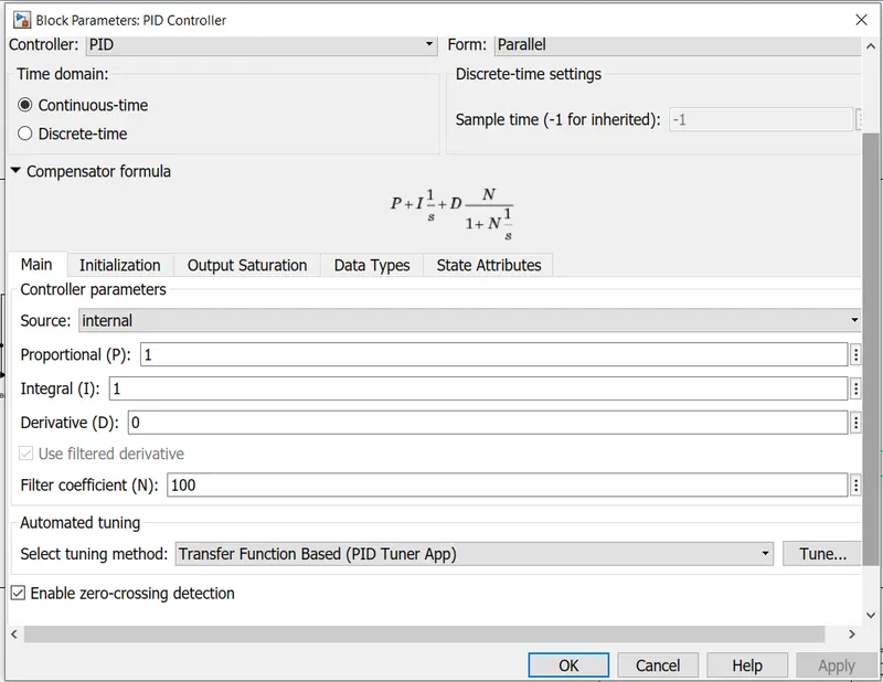
PID controller is used for speed control of EV model. PID controller blocks takes the error data between drive cycle data and actual speed of vehicle.
this is done to minimise the error.
16) SATURATION BLOCK
in order to have accleration and brake command , we use saturation block.
this block is used when we want to set limits for signals

in case of accleration command, we have set limits between 0 and 1.
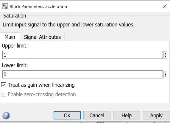

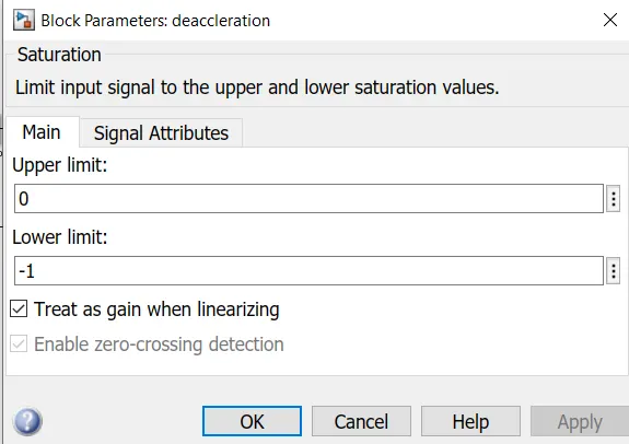
to have a deaccleration command, set the limits to 0 and -1.
17) TO MEASURE DISTANCE TRAVELLED BY ELECTRIC VEHICLE:
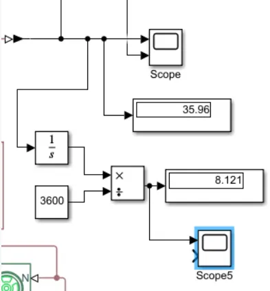
The scope will display velocity of vehicle in km/hr.
to measure the distance in km, an intergator block is used beacuse intergartion of velocity will give us distance.
and 3600 constant block is used because 1hr=3600 seconds.
thus scope 5 will give distance graph.
RESULTS:
1)
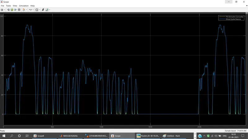
The blue line is graph of drive cycle source and yellow line shows the corresponding velocity graph.
thus found that the drive cycle input and output velocity graph is exactly overlapping on each other.
2)
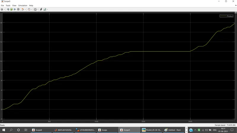
the yellow line shows the distance covered by an electric vehicle.
3)
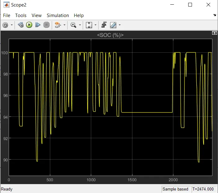
the variation of SOC is shown below.
4)
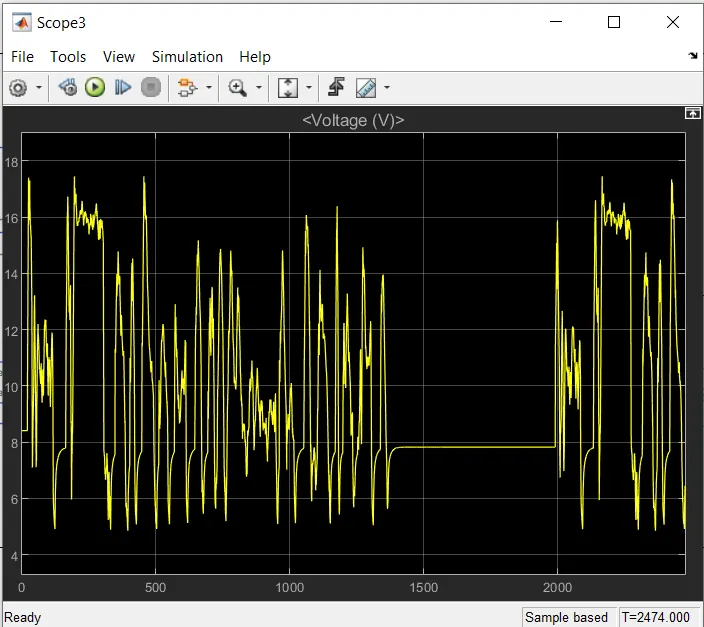
the variation of battery voltage is shown below
5)
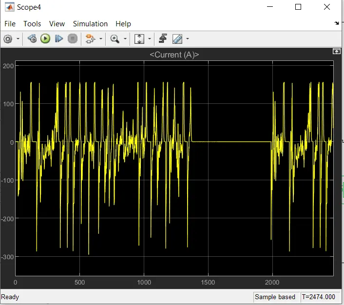
the variation of battery current is shown below
CONCLUSION:
thus all the objectives are achieved and the results are analysed properly.
REFERENCES:
https://batteryuniversity.com/learn/archive/is_lithium_ion_the_ideal_battery