Project-1: Modelling an electric Car with Li-ion battery
Aim:-
To study modelling an electric car with li-ion battery
Objective:-
Create a MATLAB model of electric car which uses lithium ion battery and suitable motor. Choose suitable blocks from Simscape or Powertrain block set. Implement the vehicle speed control using PI controller and generate brake and accelerator commands. Avoid using readymade driver block for speed control.
Q1:-
Introduction:
Electric vehicle is a vehicle, which uses one or more electric motors for propulsion. Depending on the type of the vehicle motion may be provided by rotary motor or by linear motor (in tracked vehicle).
The electricity stored in battery powered by electric motor & battery can be charged by plugging it in grid, like our phone. According to the degree of electricity used, electric vehicle is divided into 3 categories –BEV, PHEV & HEV
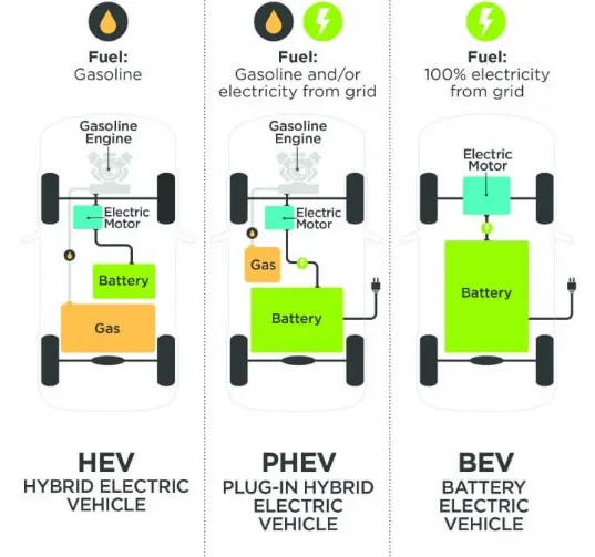
Battery Electric Vehicles (BEV) ;
BEVs are fully electric vehicles with rechargeable batteries with no engine. It stores power in battery pack & this power is used to run the vehicle & other peripherals. BEVs are charged by electricity from external source. BEVs don’t emit any hazardous emissions. Some most famous examples of this types of cars are – BMW i3, Tesla Model 3, Kia Soul, Toyota Rav4 etc.
Plug-In Hybrid Electric Vehicles (PHEV) ;
These types of vehicles are propelled by motor as well as gasoline engine. Battery is charged with regenerative braking & it can be charged with external source. PHEVs can go from 10-40 miles before assistance of engine. Examples of PHEVs – Chevy Volt, Audi A3 E-Tron, BMW i8, Toyota Prius etc.
Hybrid Electric Vehicle (HEVs) ;
HEVs are powered with both gasoline & electricity. Battery can be charged with regenerative power only. Motor supplies power from starting, engine takes care of high speed & heavy load. Controller is used to ensure best economy. HEVs are – Honda Civic Hybrid, Toyota Prius Hybrid, Toyota Camry Hybrid.
Basic Main components of Electrical vehicle:
Battery Pack;
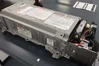
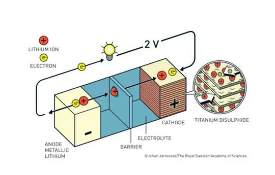
- The function of the battery in an electric car is to energy storage system in the form of (DC). If it gets a signal from controller, the battery will flow DC electrical energy to the inverter and then be used to drive the motor. The type of battery used is rechargeable battery that is arranged in such a way as to form what is called a traction battery pack.
- There are various types of electric car batteries. The most widely used is the type of lithium-ion batteries.
Power Inverter;
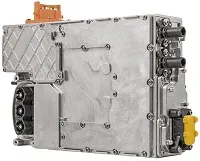
- The inverter functions to change the direct current (DC) on the battery into an alternating current (AC) this alternating current is used by an electric motor. In addition to the inverter on an electric car also has a function to change the AC current when regenerative braking to DC current and then used to recharge the battery. This type of inverter used in some electric car models is the bi-directional inverter category.
Controller;
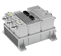
- The main function of the controller is as a regulator of electrical energy from batteries and inverters that will be distributed to electric motors. While the controller itself gets the main input from the car pedal (which is set by the driver).
- This pedal setting will determine the frequency variation or voltage variation that will enter the motor, and at the same time determine the car’s speed.
Electrical Traction Motor:
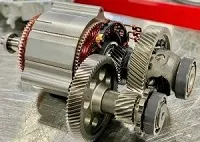
- Because the controller provides electrical power from the traction battery, the electric traction motors will work turning the transmission and also to wheels. Some hybrid electric cars use a type of generator-motor that performs the functions of propulsion and regeneration.
Other Electric Car Components:
Charger;
This is a battery charging device. Chargers get electricity from outside sources. AC electricity is converted into DC electricity and then stored in the battery.
There are 2 types of electric car chargers:
- On-board charger: the charger is located and installed in the car(inside the car)
- Off-board charger: the charger is not located or not installed in the car (outside the car)
Lithium Ion Battery :
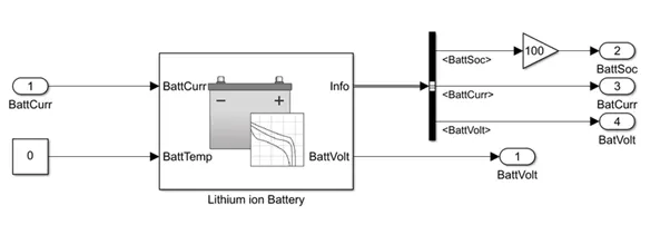
The battery pack is packed with 30 Nos. of cells in series and 2 Nos. of cells in parallel each.
Rated capacity of the battery (Ah) = 100
Output Voltage = 12 V.
The battery rated capacity is 100 Ah & rated voltage is 12 the battery provides 1200 Kwh considering its charging/discharging.
Charging of the battery – if applied current is 10 Amps. Then it would be 100 Ah/10A = 10 Hrs. Approx.
Discharging – Battery Ah X Battery Volt/Applied Load. Say 100 Ah. X 10V/100 Watts = 12 Hrs. (With 40 % loss at the max = 12 X 40 /100 =4.8 Hrs.)
The battery is the energy source of any system. the battery used in the system is the datasheet battery which implements the model for the Lithium-Ion Battery. The reason behind popularity of these cells batteries in EVs low discharge rates compared to capacitor banks also less expensive & required less maintenance and constant monitoring than Hydrogen cells. Lithium Ion battery eliminates all these disadvantages and requires fewer operational costs.
Lithium Ion battery has average life span for more than 8 years. Safety reduce the risk of accidents by eliminating exposure to flammable fuels. Able to withstand even in the high temp. without high temperatures.
Also, Lithium Ion batteries provide significant environmental benefits over fossil fuels. With steady increase in the electric vehicle we can see the immediate impact on the reduction in carbon emission.
Hence knowing all such advantages of Lithium Ion Manufacturers prefer using lithium cells as their main source of energy.
Formula to calculate SoC –
SOC (t) = SOC (t-1) + Bat.dt
Where,
SOC(t) = State of Charge at time (t).
SOC(t-1) = Initial State of Charge.
I = Charge/Discharge current (A).
t = Time (H).
CBat = Battery Capacity.
The BattCurr and the BattVolt are connected to the motor controller respectively. the BattSoC can be determined by the Bus Selector & the SoC is scaled to 100 by using a gain block.
Parameters for Battery –
Battery type = Lithium Ion Battery.
Battery Charge Max. = 100 Ah.
No. of Cells in Series = 30
No. of Cells in Parallel = 2
Output Battery voltage = 12.
Vehicle subsystem:
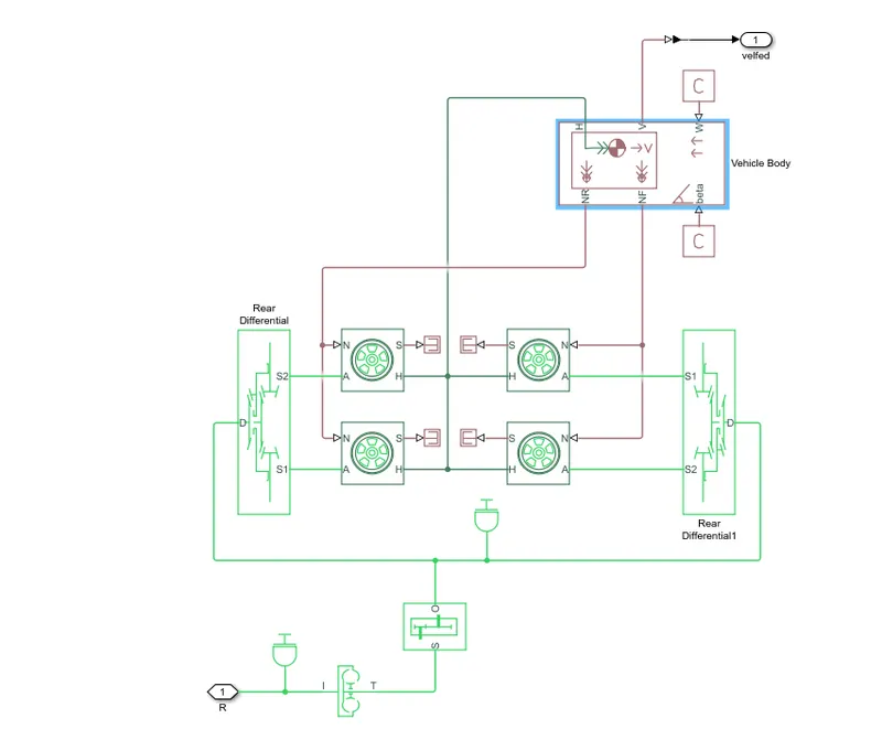
Block are Used:
- Vehicle body
- Constant
- Display
- Input,Output port
- Tire
- Differential
- Simple Gear
- Inertia
- Dc motor
DC Motor:
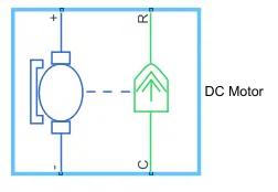
- Simulink Provides an inbuilt model block for a DC motor which converts electrical input into mechanical rotational output.
- Note the blue colour corresponds to the electrical side of the motor and the green colour corresponds to the mechanical side
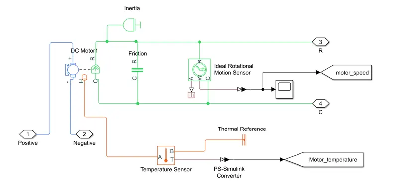
- Here thr motor field type is kept as Permanent magnet and the model parameterization is done by ratedd load and speed. The armature inductance and the mechanical parameters are given as their default values.
We consider the Inertia and the Friction and also the Temperature Sensor:
The PWM and REF connection are for the corresponding ports on the H-Bridge Circuit.The two reference inputs corresponds to the throttle inputs given by the driver.The block generates corresponding pulse width as per the acceleration and brakes applied by the driver himself.Here the PWM frquency is 4000Hz. Also the simulation mode is Averaged as that in the H-Bridge circuit
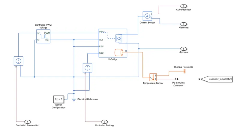
- The value of acceleration forces yields more power and must be given from the battery source. The top speed is according to the drive cycle is met by adjusting the motor controller and PWM source.
- A power electronic converter is an electronic device made of high-power semiconductor switches that use different switching states to change the magnitude and waveform of voltage between input and output. Power converter circuits are used to control the flow of energy by supplying the right amount of current and voltage with help of power semiconductor switches. Power electronics deals with the conversion and control of electrical energy with the help of power semiconductor devices that operate in a switching mode, and, therefore, the efficiency of power electronic apparatus may approach as high as 98–99%. They can be uni or bidirectional.
There are four possible types of power electronics converters namely
a) AC to DC converters (controlled rectifiers).
b) AC to AC converters (AC voltage controllers).
c) DC to AC converters (Inverters).
d) DC to DC converters (DC choppers). - PE circuits can apply power varying from tens of watts up to hundreds of megawatts. They have high energy conversion efficiency. In a power electronic circuit, there exists only periodic linking of a power source to the load. This acts like an ideal switch where during an on the state there is null resistance and during off state, there is infinitesimally high resistance. The usage is preferred due to the absence of dissipation elements and power losses being nearly equal to zero. The duty cycle of a signal measures the fraction of time a given transmitter is transmitting that signal. This fraction of time determines the overall power delivered by the signal. Signals with longer duty cycles carry more power. This makes the signal stronger, more reliable, and easily detected by receiving equipment. Signals with longer duty cycles require less efficient receivers than do signals with shorter duty cycles.
- Depending upon maximum acceleration and retardation values in a duty cycle, the values must be chosen to step up and step down voltages.
- H-Bridge- This block represents an H-bridge motor drive. The block can be driven by the Controlled PWM Voltage block in PWM or Averaged mode. In PWM mode, the motor is powered if the PWM port voltage is above the Enable threshold voltage. In Averaged mode, the PWM port voltage divided by the PWM signal amplitude parameter defines the ratio of the on-time to the PWM period. Using this ratio and assumptions about the load, the block applies an average voltage to the load that achieves the correct average load current. The Simulation mode parameter value must be the same for the Controlled PWM Voltage and H-Bridge blocks.
- During regenerative braking, the battery is charged. During the deceleration stage, energy should be recovered from the machine. For this purpose, the power converter must be bidirectional in current in order to ensure regenerative braking during deceleration stages. The motor drive's operation is performed.
- H-Bridge parameters -
Output:
The plot of the drive cycle is shown below;
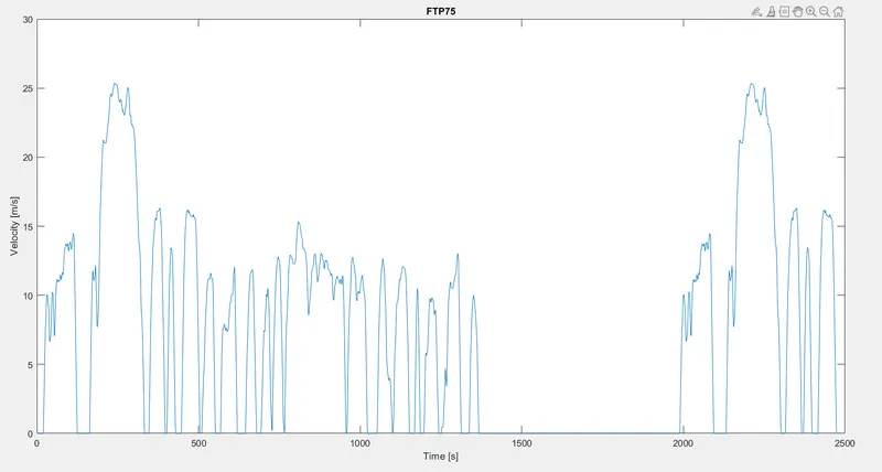
- In this model we use three different drive cycle like WTO, FTP75 and also through Signal Builder.
- The Controller will follow the given drive cycle reference and run the motor is the required rpm.
- The Current flows to DC Motor from the battery through the DC-DC Power Converter to the drive the motor.The required Voltage will be controlled in the Controller.
- Then the motor power is transmitted to the wheels of a vehicle through the gearbox, the controller will take the vehicle speed and the speed of the vehicle is as given in the drive cycle.
MATLAB Model of Electric Car which uses Li-ion Battery and a Suitable Motor
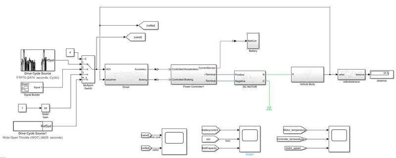
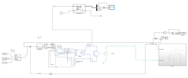
- The electric Vehicle model is represented by using MATLAB/Simulink.This model is a complete representation of an electric vehicle that is built using Powertrain Blockset.
- This model has vehicle dynamics and electrical system, the vehicle dynamics subsystem relates to the vehicle body and tires whereas the electrical system contains a subsystem related to the motor and battery pack. This subsystem contains various other componente which we will understand further
Result:
- The run time is kept at 2474 seconds because the total run time of the FTP drive cycle is 2474seconds.
- Now we will see the actual drive cycle and the reference cycle.
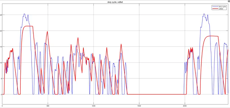
- From the plot it is evident that the actual drive cycle is almost matching with the reference drive cycle.
- But the peak velocity is lesser in the actual drive cycle(22m/s). This is because of many factors, The rolling resistance of the vehicle is taken into the consideration and hence this will affect the velocity of the vehicle.
- The wind velocity also affect the speed of the Vehicle.
From this drive cycle the Vehicle can able to cover the distance of 17.69
Battery Current ,SOC and the Battery Capacity:
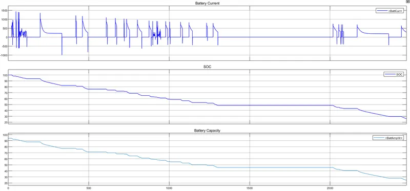
- The State of Charge in the FTP75 drive cycle is from 100 to 22 and the Battery Capacity is 94Ah and it reduced due to the drive cycle and it reaches 25Ah in 2474sec of the drive cycle and this is due to the when the vehicle is before start the Battery Capacity is high when it drive the charges present in the battery is keep on reducing so that battery capacity is keep on reducing when it reduced Completly the Battery need to be charge.
Motor Temperature, Controller Temperature and the Motor Speed:
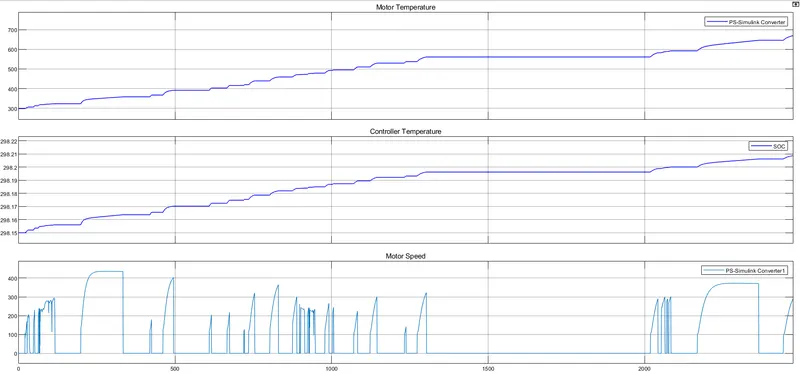
- The motor perform based on the drive cycle when the drive cycle reference velocity increased motor speed keep on increasing when it reduce the motor speed keep on reduced but it does not match exactly with drive cycle because the motor operation when the drive cycle is reduced fastely the motor cannot able to reduce that much fast because the braking operation performed here from 100-0 it takes atleast 10sec so that we cannot match exactly with the drive cycle.
- The motor temperature is increased from 300 to 700 within 2474 we need to provide coolant in this system so that motor perform better and controller temperature is maintained some what constant in this system.
Motor Temperature, Controller Temperature and the Motor Speed:
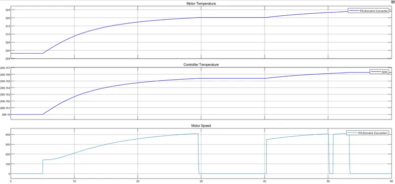
- The motor perform based on the drive cycle when the drive cycle reference velocity increased motor speed keep on increasing when it reduce the motor speed keep on reduced but it does not match exactly with drive cycle because the motor operation when the drive cycle is reduced fastely the motor cannot able to reduce that much fast because the braking operation performed here from 100-0 it takes atleast 10sec so that we cannot match exactly with the drive cycle.
Conclusion:
We Create a MATLAB model of an electric car which uses lithium ion battery with suitable motor and by using suitable blocks from the Simscape or Powertrain Block set , We Implement the vehicle speed control using PI Controller and generate a brake and accelerator commands, we have seen the System level Configuration is completed.