Week - 4
Aim:
TO implement control logic of a Washing Machine uing Stateflow
Make a simulink chart for the Gear shift using stateflow
Q1:
In simulink implement the control logic of a Washing Machine using stateflow as per given input conditions,
creae a model and operate the model logic system an output an results
Explanation:
Provides a graphical languages are Flowcharts ,state transition tables and truth tables by using MATLAB
A washing Machine has fully automatic an using the on of physical signals
The stateflow is a simulink tool to implement the model, the inputs are
If the power supply is available, the system gets activated
If the Water supply is not available, stop the process & indicate through LED
Soaking time should be 200s followed by Washing time of 100s.
Then rinsing happens for next 20s & dryer runs for 50s
Chart:
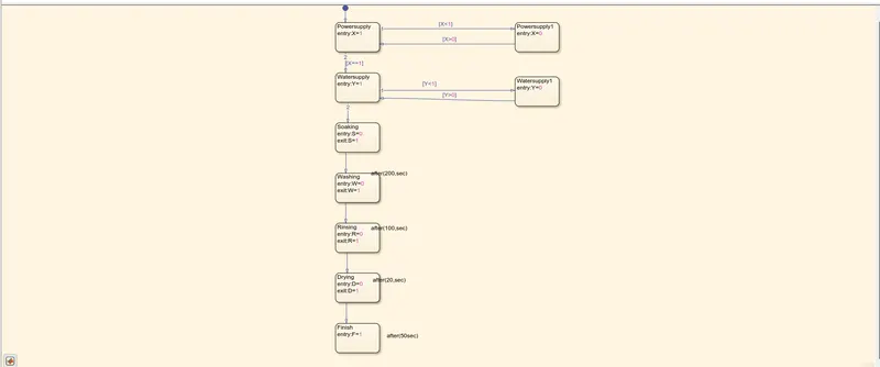
Given the input values for turning ON an OFF the power supply and water supply.
VALUE=1 power and water turn ON condition
VALUE=0 power an water turn OFF condition
Simulink:
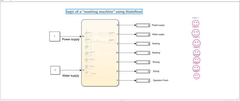
The output is displayed an using the lamp is on an off(pink smile )
Q2:
Create a modle for gear shifting logic as per given conditions given the speed input while simulation is running
Explanation:
It us a mechanical device that enable the driver to engage gears in obtain as the transmission retio called gear shifting
The Given conditions are;
Speed Range(kmph) Gear
0 to 15 1
16 to 25 2
26 to 40 3
41 to 60 4
Above 61 5
Chart:
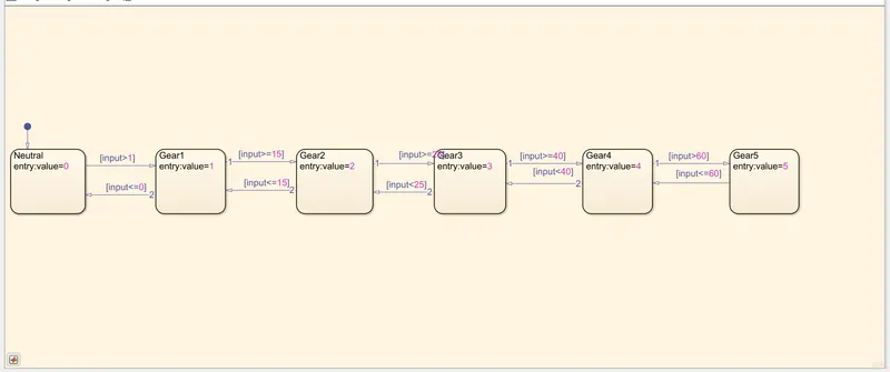
The connections are slindre gain is acting a speedometer in running time
Create the constant and giving value 1 and 0 for ON an OFF
Cerate the lamp to indicate the power ON an OFF (pink smile symbel)
The mouste impartant of gear position display block
Simulink:
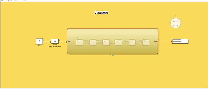
Result:
Q1;Thus the control logic of a washing machine using stateflow is processed as per the given sequence and pink LED
lights are turns to the green colour and the system is completed.
Q2; Simulink model is created for the gear shift logic and using the value is obtained.