Project-1: Modelling an electric Car with Li-ion battery
OBJECTIVES
Create a MATLAB model of electric car which uses lithium-ion battery and suitable motor. Choose suitable blocks from Simscape or Powertrain block set. Implement the vehicle speed control using PI controller and generate brake and accelerator commands. Avoid using readymade driver block for speed control.
Prepare a report about your model including following:
Objectives, System level configurations, Model parameters, Results, Conclusion.
(Note- The Simulink model file should be compulsorily attached)
ANSWERS
AIM:
- To make an Electric car model which uses li-ion battery in MATLAB Simulink environment.
OBJECTIVE:
- Create a MATLAB model of electric car which uses lithium-ion battery and suitable motor. Choose suitable blocks from Simscape or Powertrain block set. Implement the vehicle speed control using PI controller and generate brake and accelerator commands. Avoid using readymade driver block for speed control.
- Prepare a report about your model including following:
- Objectives, System level configurations, Model parameters, Results, Conclusion
Methodology :
- The electric vehicle consists if a battery,motor,controller then its generates propulsion power.
- to design an EV first we need to calculate propulsion power then we will select motor type.
- then we need to select motor and battery for suitable range and vehicle parameters.
- in market many types of motor,controller and battery avaiable.
- so,here we are selecting li ion battery and DC motor.
THEORY
An electric vehicle (EV) is defined as a vehicle that uses an electric motor or a traction motor for propulsion as opposed to an internal combustion (IC) engine used by conventional vehicles. Electric vehicles use electricity for power instead of fossil fuels as conventional vehicles would and because of this difference, electric vehicles do not produce any exhaust gases or pollution. The power needed for the operation of an EV can come from a variety of sources such as batteries, generators, or through a collector system. Batteries fitted in to the body of an EV are capable of high energy densities in order for them to meet the power demands and range requirements. Generators are machines which generate electrical energy from an input of mechanical work and are a part of the electric motor, and they operate during braking to produce the phenomenon of 'regenerative braking'. Collector systems are off-vehicle systems which allow for the charging of an EV from homes or public charging stations. The electricity used for charging in these systems are generated from solar panels which can be used by the grid or by homes of EV owners so that they can charge their vehicles more conveniently.
EVs are increasing in demand in recent years due to the need to reduce vehicle emissions which are damaging to the environment. Government incentives and private companies are working on schemes to quicken the adoption of electric vehicles. Since EVs do not produce any emissions, they are more environmentally friendly than conventional vehicles are. The generation of the electricity used to charge the vehicles also comes from solar energy (a renewable energy source) and not fossil fuels which makes them sustainable. EVs can meet the same performance standards of conventional vehicles and even surpass that of theirs and this has been seen with the automotive company Tesla. The Tesla Model 3 is the best-selling EV in the world and is capable of a range of approximately 350km on single charge. It also has an acceleration of 0 - 60 mph in 5.6 seconds and a top speed of 130 mph.
EVs offer several advantages over conventional vehicles besides the lack of pollution and lack of need to rely on fossil fuels. One is that, EVs are more efficient meaning that they offer more MPGs (miles per gallon gasoline equivalent), meaning that you will spend lesser on recharging an EV than you would to refuel a conventional vehicle. This because the more efficient the EV is, the more distance you travel with the available energy. In the US, Tesla owners can charge their EVs for free at their private charging stations for life which results in significant savings in fuel. Regenerative braking in EVs adds to their efficiency as the unused energy in braking gets reused purposefully. Another benefit is that EVs have fewer moving/rotating parts and this means lesser maintenance costs than you would have with IC engine vehicles e.g. changing oil, transmission fluid. This, in the long term would give better savings than you would get with conventional vehicles. Lesser moving parts means there is lesser friction between moving parts and hence quieter operation.
In spite of these feats, it will be difficult for a worldwide adoption of EVs for several reasons. One reason is convenience. In order for EVs to dominate the automotive market, their needs to be more convenient ways for consumers to be able to charge their vehicles. Their needs to be several charging stations on the highways and roads and this can be supported if everyone's homes were generating solar power. It needs to be as easy to charge an EV as it is to fill an IC engine vehicle with fuel at a petrol station. Another reason is the cost of the EVs. EVs are still a relatively new technology and only account for 2-3% of the worldwide market. This is because they cost considerably more than conventional vehicles due to the high cost of batteries and electric components. But, the cost of batteries is getting cheaper over time and manufacturers are developing newer and more efficient batteries. The goal is to produce a 'million mile' battery which, if made will be a revolution in the automotive sector. Another disadvantage is that the components in EVs operate at high voltages and currents and this can be a hazard if the components explode or don't work as they should.
A compromise between IC engine vehicles and EVs exists as Hybrid Electric Vehicles (HEVs). HEVs combine an IC engine with an electric propulsion system to produce a 'hybrid' between the two different classes of vehicles. The purpose of this is to use the power available from the electric powertrain to improve the fuel economy of the vehicle so that it does not rely solely on the petrol/diesel it uses as fuel. This in turn will also improve the overall performance of the HEV. The IC engine can be used to power the electric motor to charge the battery or use directly in the electric drive motor with a combination of a motor and generator in one. HEVs also implement regenerative braking to recharge their batteries among other features used in EVs. Compared to EVs, HEVs represent more of the automotive market with a 19% market share on all automobiles in the world. This is because HEVs still run-on fossil fuels which is still more convenient as a fuel source in most parts of the world. The all-time bestselling HEV to date is the Toyota Prius.
In this report, I will be modelling an electric vehicle with a DC motor and battery system using the SIMULINK software. The components I will need for my model exist as blocks in the SIMULINK block library. I will be modelling this EV for a drive cycle and measure the velocity characteristics and the current and SOC characteristics of its battery system.
The main work of vehicle is to move people,goods or anything we want from one place to another place.we can do this work by many option ike we can use of animals,use of boat,plane,train and vehicle.in vehicle we can use two wheeler,three wheeler, four wheeler, trucks,crains,etc...and these vehicle are conventional like they use petrol,diesel fossil fuel,some are using gas(LPG,CNG,etc),but its harmfull for environment and it will create pollutonlike Air aswell noice pollution.so what i am trying to say is we just need to go one to another direction so why we cant use that things which is pollution free,have a enough speed,less cost,high torque,and human friendly.so for that we can add electric vehicle in this list.apart from this we can use HEV(hybrid electric vehicle),fuel cell vehicle by using hydrogen as fuel cell,ethanol based vehicle and in future we can find many options aswell.
An electric vehicle (EV) is defined as a vehicle that uses an electric motor or a traction motor for propulsion as opposed to an internal combustion (IC) engine used by conventional vehicles. Electric vehicles use electricity for power instead of fossil fuels as conventional vehicles would and because of this difference, electric vehicles do not produce any exhaust gases or pollution. The power needed for the operation of an EV can come from a variety of sources such as batteries, generators, or through a collector system. Batteries fitted in to the body of an EV are capable of high energy densities in order for them to meet the power demands and range requirements. Generators are machines which generate electrical energy from an input of mechanical work and are a part of the electric motor, and they operate during braking to produce the phenomenon of regenerative braking. Collector systems are off-vehicle systems which allow for the charging of an EV from homes or public charging stations. The electricity used for charging in these systems are generated from solar panels which can be used by the grid or by homes of EV owners so that they can charge their vehicles more conveniently.
EVs offer several advantages over conventional vehicles besides the lack of pollution and lack of need to rely on fossil fuels. One is that, EVs are more efficient meaning that they offer more miles per gallon gasoline equivalent, meaning that you will spend lesser on recharging an EV than you would to refuel a conventional vehicle. This because the more efficient the EV is, the more distance you travel with the available energy. In the US, Tesla owners can charge their EVs for free at their private charging stations for life which results in significant savings in fuel. Regenerative braking in EVs adds to their efficiency as the unused energy in braking gets reused purposefully. Another benefit is that EVs have fewer moving/rotating parts and this means lesser maintenance costs than you would have with IC engine vehicles e.g. changing oil, transmission fluid. This, in the long term would give better savings than you would get with conventional vehicles. Lesser moving parts means there is lesser friction between moving parts and hence quieter operation.
A compromise between IC engine vehicles and EVs exists as Hybrid Electric Vehicles. HEVs combine an IC engine with an electric propulsion system to produce a 'hybrid' between the two different classes of vehicles. The purpose of this is to use the power available form the electric powertrain to improve the fuel economy of the vehicle so that it does not rely solely on the petrol/diesel it uses as fuel. This in turn will also improve the overall performance of the HEV. The IC engine can be used to power the electric motor to charge the battery or use directly in the electric drive motor with a combination of a motor and generator in one. HEVs also implement regenerative braking to recharge their batteries among other features used in EVs. Compared to EVs, HEVs represent more of the automotive market with a 19% market share on all automobiles in the world. This is because HEVs still run on fossil fuels which is still more convenient as a fuel source in most parts of the world. The all time best selling HEV to date is the Toyota Prius.
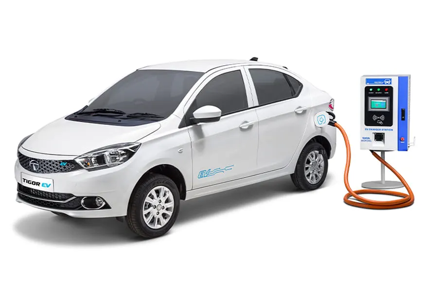
.
There are basically three different kinds of electric vehicles: hybrid electric vehicles, plug-in hybrid electric vehicles and battery electric vehicles. All three varieties of electric vehicles use electricity for propulsion, but there are differences in how they operate and their respective powertrains and electric range. Below we will be reviewing the different benefits of electric vehicles and how each compare to one another.
Hybrid Electric Vehicles (HEVs)
Hybrid electric vehicles are typically referred to as “hybrids,” and although the technology has been around for decades, the cars didn’t really have material market penetration until 1997 when Toyota introduced the Prius. Since then, the Toyota Prius has been the world’s best-selling car and the most recognizable hybrid electric vehicle with its Prius battery However, there are a number of hybrid models on the market today including the Kia Optima Hybrid, Ford Fusion Hybrid, Kia Niro, Hyundai Ioniq HEV and several others.
Hybrid electric vehicles combine a conventional internal combustion engine with an electric propulsion system. The internal combustion engine (typically a petrol or gasoline engine) does most of the work, while the electric motor assists the engine, with its main purpose being to increase the fuel economy.
Hybrids do not have the ability to plug in and recharge from the grid, so they use their internal combustion engines and regenerative braking systems to recharge their propulsion vehicle batteries. Most hybrids do not have the ability to propel the car on battery power alone, and must have the combustion engine running whenever the vehicle is moving. However, there are a few hybrids that can propel the vehicle for a few feet at low speeds, before the combustion engine needs to turn on and assist.
Hybrid electric vehicles have better fuel economy and a lower total cost of ownership when compared to similar conventional cars, however they usually also cost more to purchase initially. For example, the Toyota Prius gets up to 54 mpg in urban environments and 50 mpg on the highway, while other conventional gas-powered sedans get less mileage like the Volkswagen Passat TDI gets 35 mpg, the Nissan Altima gets 31 mpg and the Mazda6 gets 32 mpg.
Plug-in Hybrid Electric Vehicles (PHEVs)
The biggest difference between a regular hybrid vehicle and a plug-in hybrid electric vehicle is that the plug-ins have larger batteries and can be plugged in to charge the batteries. They also typically have larger electric motors, because PHEVs are responsible for more work.
Since plug-in electric cars have larger vehicle batteries, they can propel the car for a period of time without the assistance of the combustion engine. Some plug-in electric cars, like the Chrysler Pacifica Hybrid, Ford C-Max Hybrid and Honda Clarity PHEV can go 30 to 50 miles on the battery alone, and the BMW i3 REx plug-in hybrid can go 126 miles on its battery before the gasoline combustion engine needs to turn on.
Plug-in hybrids can be an excellent choice for consumers who need or want additional range. For those that need to drive very long distances on a frequent basis, a plug-in hybrid offers the flexibility of being able to quickly fill up with gasoline where charging stations may not be available. Plug-in hybrids allow their owners to drive entirely on electricity on the days when they don’t exceed the vehicle’s all-electric range, yet have the combustion engine there when they need it.
While owners will want to keep their plug-in hybrids charged as often as possible to enjoy the savings that driving on electricity provides, they aren’t required to charge the battery in order to use the vehicle. Plug-in hybrids will act like a conventional hybrid electric vehicle if they aren’t charged up from a wall outlet. Therefore, if for some reason the owner forgets to plug the vehicle in one day or drives to a destination that doesn’t have access to an electricity supply, it’s not an issue. Generally, fuel costs are higher when using the gas-powered combustion engine versus electric power.
Below are some of the best electric car plugin hybrids available in the U.S. market today: the Toyota Prius Prime, the Ford Fusion Energi and the Honda Clarity PHEV. As you can see, you can charge the batteries significantly faster with a JuiceBox Pro 40 240V smart charger, allowing you to enjoy more time driving on electrons, and less time at the pump.
| Plug In Hybrid Model | Max Charge Rate | Battery Size | Charge Time with L1 charger | Charge Time with Juicebox Pro 40 | All Electric Range |
|
Toyota Prius Prime Ford Fusion Energi Honda Clarity PHEV |
3.3 kW 3.3 kW 6.6 kW |
9 kWh 9 kWh 17.7 kWh |
6 hrs 6 hrs 14 hrs |
2.5 hrs 2.5 hrs 3 hrs |
25 miles 26 miles 47 miles |
Battery Electric Vehicles (BEVs)
Battery electric vehicles, or BEVs, are often just called electric vehicles. Unlike HEVs and PHEVs, BEVs are powered entirely by batteries, with a full-electric drivetrain.
In fact, that’s one of the advantages of battery electric vehicles, their simplicity. There are so few moving parts in a battery electric vehicle that very little maintenance is required. There’s no oil changes or tune-ups needed, and the savings from not having these maintenance expenses can add up to significant savings over the lifetime of the vehicle. Though, you do need to be aware of your electric car battery lifespan.
Since battery electric vehicles rely solely on the amount of stored electricity in their batteries, it’s even more important to be able to recharge them quickly, than it is for plug-in hybrid models. Therefore, it’s important to choose a home charging solution that can fully recharge your BEV as quickly as possible, so you can enjoy the vehicle to its fullest.
Most battery electric vehicles come standard with a 120-volt level 1 charger, which can take very long to recharge the vehicle. That’s because battery electric vehicles have much larger batteries than HEVs or PHEVs do. Take a look at the graph below to see the battery size, driving range and charging times of four of the popular battery electric vehicles available today.
| BEV Model | Max Charge Rate | Battery Size | Charge Time with L1 charger | Charge Time with Juicebox Pro 40 | Driving Range |
|
Tesla Model S 75D Chevy Bolt EV Nissan LEAF ePlus BMW i3 |
11.5 kW 7.7 kW 6.6 kW 7.7 kW |
75 kWh 60 kWh 62 kWh 42 kWh |
65 hrs 48 hrs 52 hrs 35 hrs |
8 hrs 8.5 hrs 10 hrs 5.5 hrs |
237 miles 238 miles 226 miles 153 miles |
PHEV versus BEV Costs
Today, the battery accounts for the lion’s share of the cost to build an electric vehicle, and the bigger the battery, the more expensive the car. In this respect, PHEVs have an upfront cost advantage over BEVs because they have smaller batteries. However, PHEVs incur other costs that BEVs do not like the internal combustion engine and ongoing PHEV maintenance, which is more similar to a gas-powered vehicle. Depending on the driving routine of a PHEV, the total cost of ownership over the lifetime of the vehicle can be comparable to a BEV.
There are a number of more affordable BEV models entering the market that include the Chevy Bolt EV, the Nissan Leaf, the Tesla Model 3, the Hyundai Kona Electric, etc. When BEVs first entered the North American market about a decade ago, the cars were significantly more expensive, and to combat the sticker shock of BEVs and accelerate battery electric vehicle adoption, the U.S. began offering a $7,500 federal tax credit, along with additional state and local policy incentives to expand charging infrastructure. The incentives have helped research and development efforts as battery energy density has significantly increased and come down in cost year over year. The market is at a point where auto manufacturers are reaching greater volume production.
Overall, the market trend is that the average new vehicles are increasing both in horsepower fuel economy, ultimately reducing their carbon footprint. A number of contributing factors are driving this trend towards cleaner, more powerful vehicles including consumer preferences, regulations and innovation.
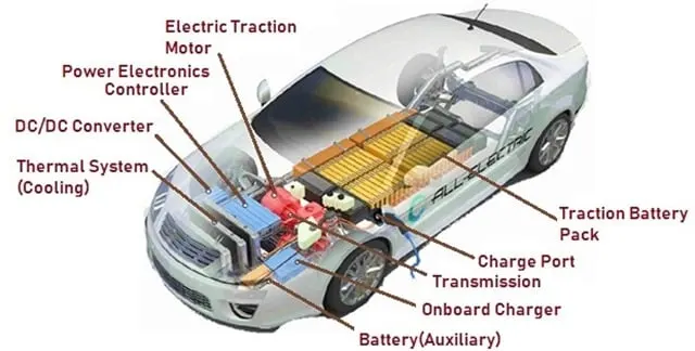
The main components of an electric vehicle are:
- Battery (auxiliary)
- Electric traction motor
- Onboard charger
- Thermal system (cooling)
- Power electronics controller
- Inverter
- Charge port
- Transmission
- DC to DC converter
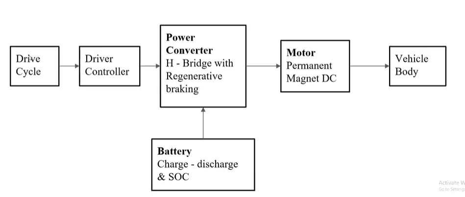
Block Diagram of the Electric Vehicle shown below:
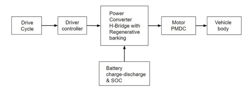
BLOCK DIAGRAM
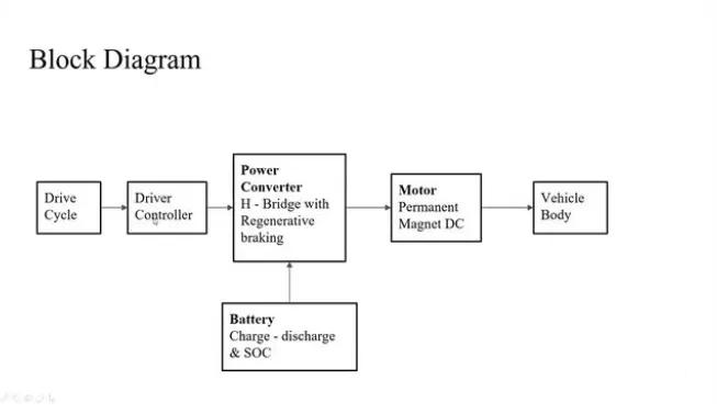
EV design
Today’s EVs are very different from ICE (internal combustion engine) gasoline-powered vehicles. The new breed of EVs has benefited from a series of failed attempts to design and build electric vehicles using traditional methods of production used by manufacturers for decades.
There are numerous differences in how EVs are manufactured when compared to ICE vehicles. The focus used to be on protecting the engine, but this focus has now shifted to protecting the batteries in manufacturing an EV. Automotive designers and engineers are completely rethinking the design of EVs, as well as creating new production and assembly methods to build them. They are now designing an EV from the ground up with heavy consideration to aerodynamics, weight and other energy efficiencies.
- The single biggest modification of the car is the underbody. While this structure has been very similar in the past, with EVs there is no engine and there are no exhaust systems needed. There is an aerodynamically designed full belly pan under the EV that contains trays where the battery pack is placed. With more and more variations and shapes of battery packs available for different models, the challenge is to be able to make these variations on one Flexible Manufacturing System (FMS). Since all EV battery cells are quite heavy, flexible robotic lines are necessary.
- In addition, FMS production lines must accommodate many new robotically performed joining methods. In many instances spot welding is being replaced by an increased use of self-piercing rivets, gluing, sealing, flow drilling, and laser welding — and are specifically chosen depending on the tray used for each particular type of battery cell.
- The EV’s inner structure is called a “space frame” and is made of strong, lightweight aluminum — and for additional weight-savings, the wheels are also made of aluminum instead of steel. Using manufacturers molds, these aluminum parts are poured at a foundry. In addition, the steering wheel and seat frames are made of magnesium, a strong, lightweight metal. Even the body panels are made of lightweight aluminum, or an impact-resistant composite plastic. Both materials are recyclable, providing long-term disposal advantages.
- In an effort to reduce weight, the structural frame, seat frames, wheels and body are designed for high-strength, safety — and the lightest possible weight. New configurations have been developed that provide support for the components and protection of the vehicle occupants with minimal mass and use of high-tech materials, including aluminum, magnesium and advanced composite plastics.
- The windshield is solar glass that keeps the interior from overheating in the sun and frost from forming in winter. Materials that provide thermal conservation reduce the energy drain that heating and air conditioning impose on the batteries.
- Some features did have to be eliminated or changed while leaving all the comforts drivers find desirable and adding new considerations as well. One feature that was removed because of space restrictions was the spare tire. This was possible because the EV tires contain a sealant to repair any leaks automatically. In addition, the tires are rubber and designed to inflate to higher pressures, so the car rolls with less resistance to conserve energy.
- An added safety consideration was a pedestrian warning system, because EVs run so quietly that pedestrians may not hear them approach. Driver activated flashing lights and beeps warn pedestrians that the car is approaching. This system works automatically when the car is put in reverse as well.
EV battery
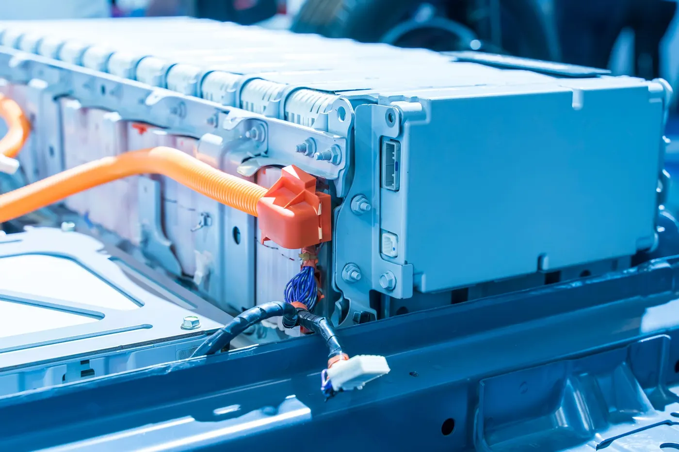
An electric vehicle battery (EVB) is the standard designation for batteries used to power electric motors of all types of EVs. In most cases, these are rechargeable lithium-ion batteries that are specifically designed for a high ampere-hour (or kilowatt-hour) capacity. Rechargeable batteries of lithium-ion technology are plastic housings that contain metal anodes and cathodes. Lithium-ion batteries use polymer electrolyte instead of a liquid electrolyte. High conductivity semisolid (gel) polymers form this electrolyte.
Lithium-ion EV batteries are deep-cycle batteries designed to give power over sustained periods of time. Smaller and lighter, the lithium-ion batteries are desirable because they reduce the weight of the vehicle and therefore improve its performance.
These batteries provide higher specific energy than other lithium battery types. They are typically used in applications where weight is a critical feature, such as mobile devices, radio-controlled aircraft and, now, EVs. A typical lithium-ion battery can store 150 watt-hours of electricity in a battery weighing approximately 1 kilogram.
In the last two decades advances in lithium-ion battery technology has been driven by demands from portable electronics, laptop computers, mobile phones, power tools and more. The EV industry has reaped the benefits of these advances both in performance and energy density. Unlike other battery chemistries, lithium-ion batteries can be discharged and recharged daily and at any level of charge.
There are technologies that support the creation of other types of lighter weight, reliable, cost-effective batteries — and research continues to reduce the number of batteries needed for today’s EVs. Batteries that store energy and power the electric motors have evolved into a technology of their own and are changing almost every day.
Traction system
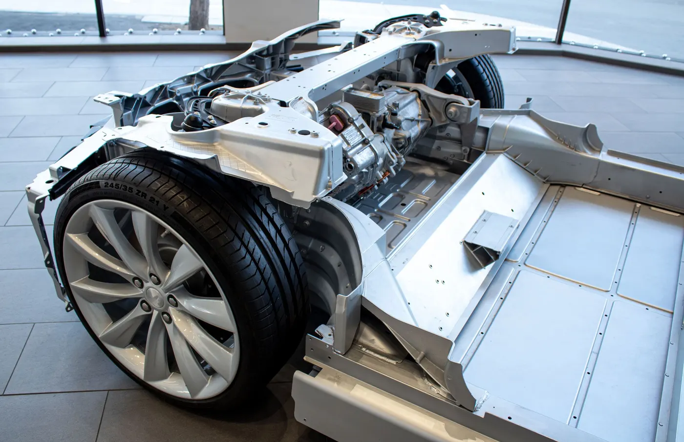
EVs have electric motors, also referred to as the traction or propulsion system — and have metal and plastic parts that never need lubrication. The system converts electrical energy from the battery and transmits it to the drive train.
EVs can be designed with two-wheel or all-wheel propulsion, using either two or four electric motors respectively. Both direct current (DC) and alternating current (AC) motors are being used in these traction or propulsion systems for EVs. AC motors are currently more popular, because they do not use brushes and require less maintenance.
EV controller
EV motors also include a sophisticated electronics controller. This controller houses the electronics package that operates between the batteries and the electric motor to control the vehicle speed and acceleration, much like a carburetor does in a gasoline-powered vehicle. These on-board computer systems not only start the car, but also operates doors, windows, air conditioning, tire-pressure monitoring system, entertainment system, and many other features common to all cars.
The controller regulates energy flow from the battery to the motors and allows for adjustable speed. Specially designed Silicon-Controlled Rectifiers (SCRs) are used for this controller. They allow full power to go from the battery to the motor but in pulses, so the battery is not overworked, and the motors are not underpowered.
The controller transforms the battery’s direct current (DC) into alternating current (AC) and regulates the energy flow from the battery. The controller will also reverse the motor rotation — putting the vehicle in reverse — and converting the motor to generators, so that the kinetic energy of motion can be used to recharge the battery when the brake is applied.
EV brakes
Any type of brake can be used on EVs, but regenerative braking systems are preferred in electric vehicles. Regenerative braking is a process by which the motor is used as a generator to recharge the batteries when the vehicle is slowing down. These braking systems recapture some of the energy lost during braking and channel it back to the battery system.
During regenerative braking, some of the kinetic energy normally absorbed by the brakes and turned into heat is converted to electricity by the controller — and is used to re-charge the batteries. Regenerative braking not only increases the range of an electric vehicle by 5 to 10%, but it also has proven to decrease brake wear and reduce maintenance cost.
EV chargers
Two types of chargers are needed. A full-size charger for installation in a garage is needed to recharge EVs overnight, as well as a portable recharger. Portable chargers are quickly becoming standard equipment from many manufacturers. These chargers are kept in the trunk so the EVs’ batteries can be partially or completely recharged during a long trip or in an emergency like a power outage. In a future issue we will further detail the types of EV charging stations such as Level 1, Level 2 and Wireless.
Software used - MATLAB R2021b
Electric car is a vehicle that is fully or partially propelled by electric motors, using energy stored in rechargeable batteries.
- The first practical electric cars were produced in the 1880s. Electric cars were popular late 19th century and early 20th century.
- Innovation and advanced development in the internal combustion engines (ICE) and mass production of cheaper gasoline vehicles has led to a decline in the use of electric vehicles.
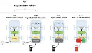
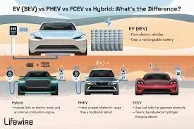
- Different types of electric cars changed and are developed continuously giving users and potential users choices. Today the world is increasingly familiar with the terms BEV, HEV, PHEV and FCEV.
How does an electric car work?
- When pedal of the car is pressed then, controller takes and regulates electrical energy from batteries and inverters.
- With the controller set, the inverter then sends a certain amount of electrical energy to the motor (according to the depth of pressure on the pedal).
- Electric motor converts electrical energy into mechanical energy. Rotation of the motor rotor rotates the transmission. So the wheels turn and then car moves.
Types of electric cars -
- Battery electric vehicle (BEV)
- Hybrid electric vehicle (HEV)
- Plug - in Hybrid electric vehicle (PHEV)
- Fuel cell electric vehicle (FCEV)
1. BEV -
- It is also called as, All - electric vehicle (AEV), runs entirely on a battery and electric drive train.
- These types of electric cars do not have an ICE. Energy is stored in a large battery pack that is charged by plugging into the electricity grid.
- The battery pack, in turn, provides power to one or more electric motors to run the electric car.
Architecture and components of BEV -
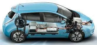
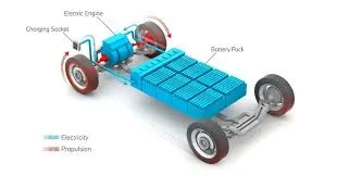
Components of BEV -
- Electric motor
- Inverter
- Battery
- Control module
- Drive train
Working principle of BEV -
- Power is converted from DC battery to AC for the electric motor.
- The accelerator pedal sends a signal to the controller which adjusts the vehicle speed by changing the frequency of the AC power from the inverter to the motor.
- The motor connects and turns the wheels through a cog.
- When the brakes are pressed or the electric car is decelerating, the motor becomes an alternator and produces power which is sent back to the battery.
Examples - Volkswagen e - Golf, Tesla model 3, BMW i3, chevy bolt, chevy spark, Nissan LEAF, Ford Focus Electric, Hyundai Ioni, Karma Revera.
2. HEV -
- This type of hybrid cars is often called as standard hybrid or parallel hybrid.
- HEV has both an ICE and an electric motor.
- In this types of electric cars, internal combustion engine gets energy from fuel, while the motor gets electricity from batteries.
- The gasoline engine and electric motor simultaneously rotate the transmission, which drives the wheels.
- The difference between HEV compared to BEV and PHEV is where the batteries in HEV can only charge by the ICe, the motion of the wheels or a combination of both.
- There is no charging port, so that the battery cannot be recharged from outside of the system.
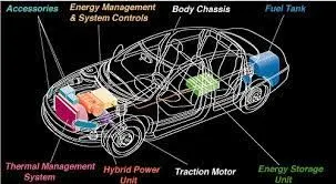
Architecture and main components of HEV -
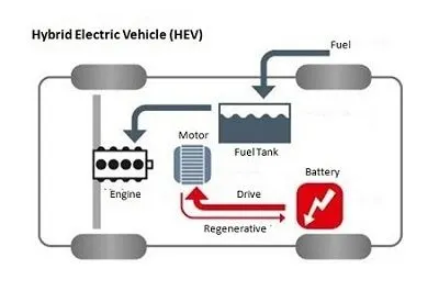
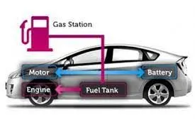
Components of HEV -
- Engine
- Electric motor
- Battery pack with controller and Inverter
- Fuel tank
- Control module
Working principle of HEV -
- Has a fuel tank that supplies gas to the engine like a regular car.
- It also has a set of batteries that run an electric motor. Both the engine and electric motor can turn the transmission at the same time.
Examples - Honda Civic Hybrid, Toyotas Prius Hybrid, Honda Civic Hybrid, Toyota Camry Hybrid.
3. Plug - in Hybrid Electric Vehicle (PHEV) -
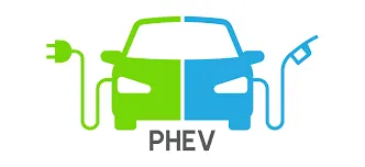
- PHEV is a type of hybrid vehicle that both an ICE and a motor, often called as series hybrid. This type of electric cars offers a choice of fuels.
- This type of electric cars is powered by a conventional fuel (such as gasoline) or an alternative fuel (such as bio - diesel) and by a rechargeable battery pack.
- The battery can be charged up with electricity by plugging into an electrical outlet or electric vehicle charging stations. (EVCS).
- PHEV typically can run in at least two modes - All electric mode, in which the motor and battery provide all the car's energy.
- Hybrid mode, in which both electricity and gasoline are employed.
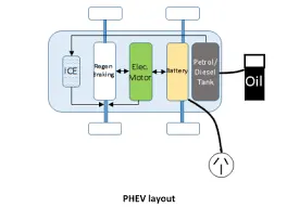
Components of PHEV -
- Electric Motor
- Engine
- Inverter
- Battery
- Fuel tank
- Control module
- Battery charger(if onboard model)
Working principle of PHEV -
- PHEVs typically startup in all electric mode and operate on electricity until their battery pack is depleted.
- Some modelsshift to hybrid mode when they reach highway cruising speed, generally above 60 - 70 miles per hour.
- Once the battery is empty, the engine takes over and the vehicle operates as a conventional, non-plug-in hybrid.
- In addition to plugging into an outside electric power source, PHEV batteries can be charged by an combustion engine or regenerative braking.
- During braking, the electric motor acts as generator, using the energy to charge the battery. The electric motor supplements the engine's power as a results smaller engine can be used, increasing the car's fuel efficiency without compromising performance.
Examples - Porsche Cayenne SE - hybrid, Chevy vott, Chrysler Pacifica, Ford C - max energy, Ford fusion Energi, Mercedes C350e, Mercedes S550e etc.
4. Fuel cell Electric Vehicle (FCEV) -
- Fuel cell electric vehicles (FCEVs), also known as fuel cell vehicles (FCVs), or zero emission vehicle, are types of electric cars that employ fuel cell technology to generate the electricity required to run the vehicle.
- In this type of vehicles, the chemical energy of the fuel is converted directly into electric energy.
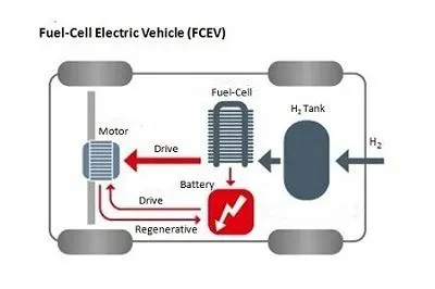
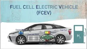
Components of FCEV -
- Electric motor
- Fuel cell stack
- Hydrogen storage tank
- Battery with converter and controller
Working principle of FCEV -
- The working principle of a fuel cell electric car is different compared to that of a plug - in electric car.
- This type of electric cars is because the FCEV generates the electricity required to run this vehicle on the vehicle itself.
Examples - Toyota Mirai, Hyundai Tuscon FCev, River simple rasa, Honda clarity fuel cell, Hyundai Nexa.
COMPONENTS OF EV VEHICLE
Electric vehicles consist of an electric motor that is powered by a battery pack. The main advantage of electric vehicles is that they emit zero emissions and are eco-friendly. They also do not consume any fossil fuels, hence use a sustainable form of energy for powering the car. The main components of electric vehicles are:
- Traction battery pack
- DC-DC Converter
- Electric motor
- Power inverter
- Charge Port
- Onboard charger
- Controller
- Auxiliary batteries
- Thermal system (cooling)
- Transmission
1.Traction battery pack
Traction battery pack is also known as Electric vehicle battery (EVB) . It powers the electric motors of an electric vehicle. The battery acts as an electrical storage system. It stores energy in the form DC current. The range will be higher with increasing kW of the battery. The life and operation of the battery depends on its design. The lifetime of a traction battery pack is estimated to be 200,000 miles.
2. DC-DC Converter
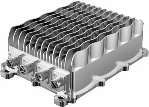
The traction battery pack delivers a constant voltage. But different components of the vehicle has different requirements. The DC-DC convertor distributes the output power that is coming from the battery to a required level. It also provides the voltage required to charge the auxiliary battery.
3.Electric motor
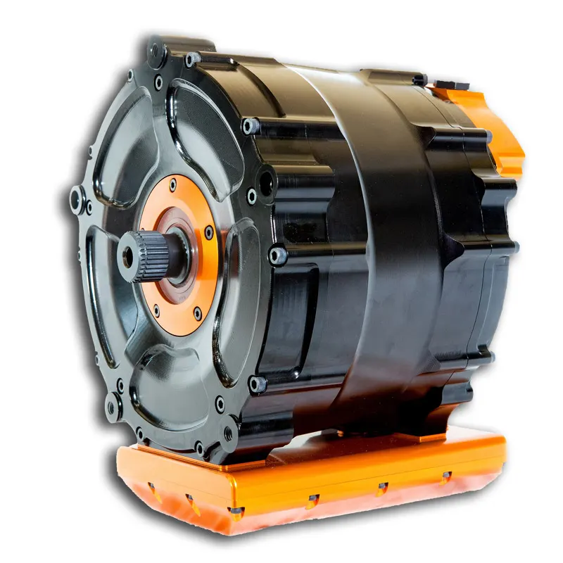
Electric traction motor is the main component of an electric vehicle. The motor converts the electrical energy into kinetic energy. This energy rotates the wheels. Electric motor is the main component that differentiates an electric car from conventional cars. An important feature of an electric motor is the regenerative braking mechanism. This mechanism slows down the vehicle by converting its kinetic energy into another form, and storing it for future use. There are basically two types of motors DC and AC motors.
4.Power Inverter
It coverts DC power from the batteries to AC power. It also converts the AC current generated during regenerative braking into DC current. This is further used to recharge the batteries. The inverter can change the speed of the
5. Charge Port
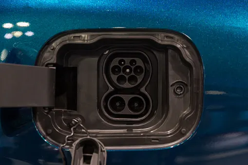
The charge port connects the electric vehicle to an external supply. It charges the battery pack. The charge port is sometimes located in the front or rear part of the vehicle
6.Onboard charger
Onboard charger is used to convert the AC supply received from the charge port to DC supply. The on-board charger is located and installed inside the car. It monitors various battery characteristics and controls the current flowing inside the battery pack.
7.Controller
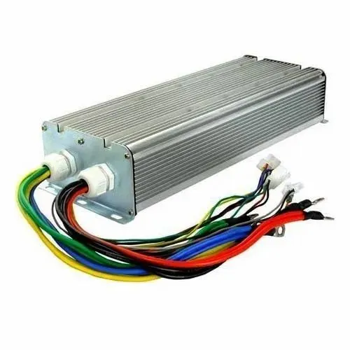
Power electronics controller determines the working of an electric car. It performs the regulation of electrical energy from the batteries to the electric motors. The pedal set by the driver determines the speed of the car and frequency of variation of voltage that is input to the motor. It also controls the torque produced.
8.Auxiliary batteries
Auxiliary batteries are the source of electrical energy for the accessories in electric vehicles. In the absence of the main battery, the auxiliary batteries will continue to charge the car. It prevents the voltage drop, produced during engine start from affecting the electrical system.
9. Thermal system(cooling)
The thermal management system is responsible for maintaining an operating temperature for the main components of an electric vehicle such as, electric motor, controller etc. It functions during charging as well to obtain maximum performance. It uses a combination of thermoelectric cooling, forced air cooling, and liquid cooling.
10. Transmission
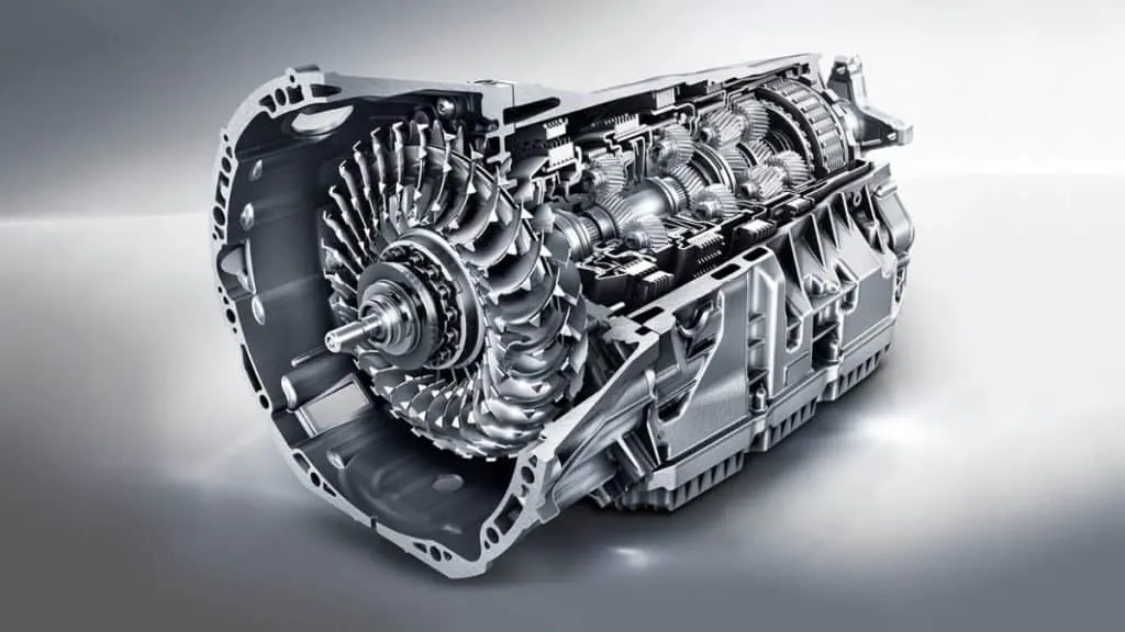
It is used to transfer the mechanical power from the electric motor to the wheels, through a gearbox. The advantage of electric cars is that they do not require multi-speed transmissions. The transmission efficiency should be high to avoid power loss.
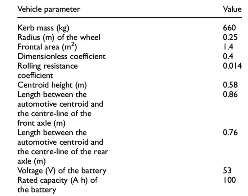
- System level configurations and Model parameters
BLOCK DIAGRAM
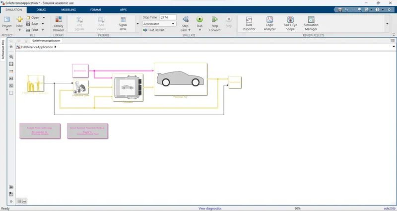
The block diagram for an Electric vehicle which uses a battery and a DC motor is shown below,
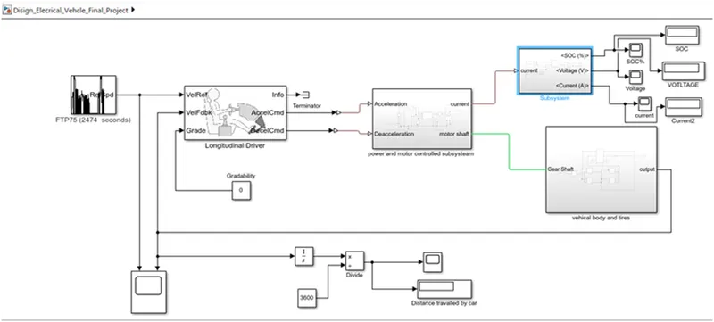
Now let us look at each of the blocks used to create this MATLAB model.
- Drive cycle data
For this we have used Drive cycle source block.
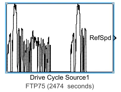
The block parameters for this block is as shown below,
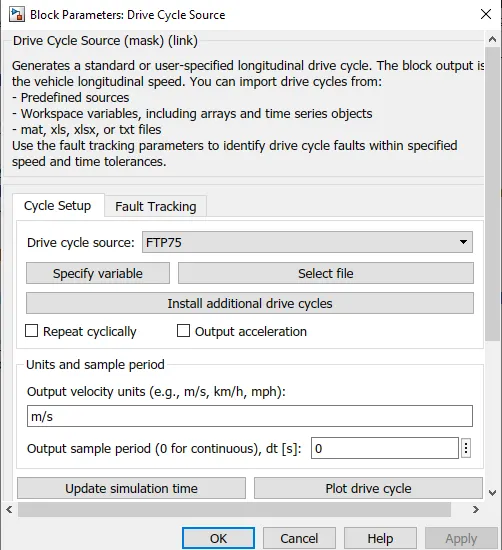
This block will help us in inputting the drive cycle data, whether it is built in or custom made by the user. That is we can use custom made drive cycle data in excel sheet using this block.
For this model we have used FTP 75 drive cycle, which is built-in in this block.
- Longitudinal driver
This block is used to create a longitudinal speed-tracking controller and it is based on reference and feedback velocities, the block generates normalized acceleration and braking commands that can vary from 0 through 1. We can use this block to model the dynamic response of a driver or to generate the commands necessary to track a longitudinal drive cycle.
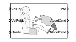
The block parameters is as shown below,
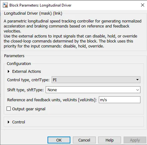
- Power control unit subsystem
This subsystem has the blocks which are used to create the voltage signals to control the motor speed as per the input drive cycle data.
THE LINK SHOWS THE EV SIMULINK MODEL
https://drive.google.com/file/d/1Ej96yXs3Scyw1QBMh--1J7gNgmmYD_tW/view?usp=sharing
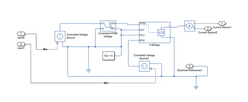
This subsystem is connected to the longitudinal driver block output ports namely acceleration command and deceleration command.
This subsystem will convert this acceleration and deceleration command into voltage signals using two controlled voltage source block, controlled PWM voltage block, a H-bridge and a current sensor.
- Controlled voltage source block
The block parameters are shown below,
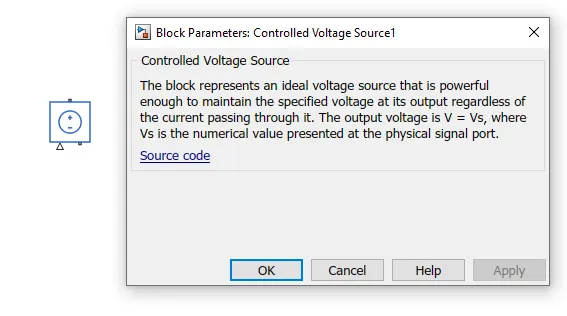
This block is used to maintain the specified voltage at its output regardless of the current flowing through the source.
- Controlled PWM voltage block
The block and its parameters are as shown below,
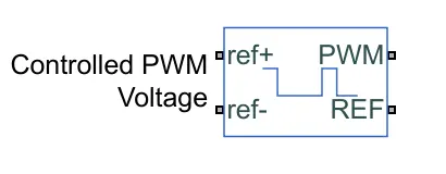
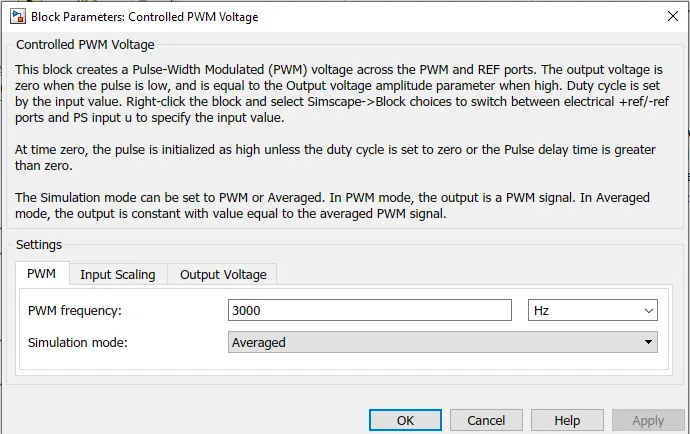
This block is used to create the pulse-width modulated (PWM) voltage.
Electrical input ports:- The block calculates the duty cycle based on the reference voltage across its ref+ and ref- ports. This modeling variant is the default.
The value of the Output voltage amplitude parameter determines amplitude of the output voltage.
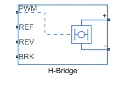
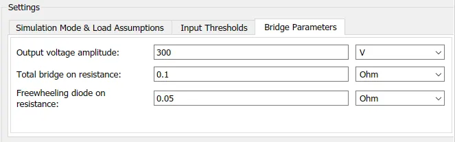
- H-bridge block
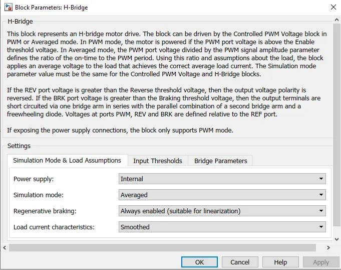
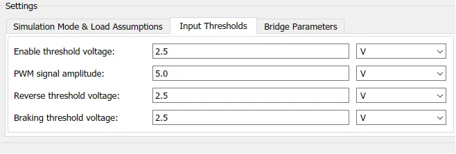
This block is used to change the polarity of the voltage applied across the DC motor so as to run the motor in forward and reverse direction as per the input command.
The block and its parameters are shown below,
- Current sensor block
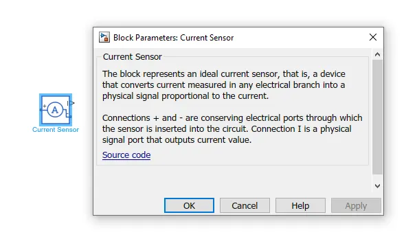
This is used to measure the current flowing through the H-bridge.
The block and its parameters is shown below,
- DC motor
To convert the electrical energy to mechanical energy we use motors. In this electric vehicle model we have used DC motor. This motor can act as a generator also in case of regenerative braking.
The motor block and its parameters are shown below,
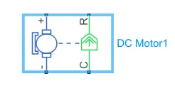
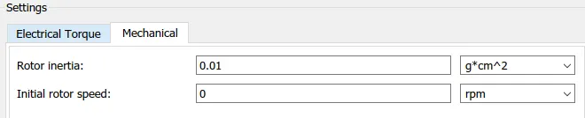
This block represents the electrical and torque characteristics of a DC motor.
- Battery subsystem
In this subsystem we have a battery block, a controlled current source block and a Goto block.
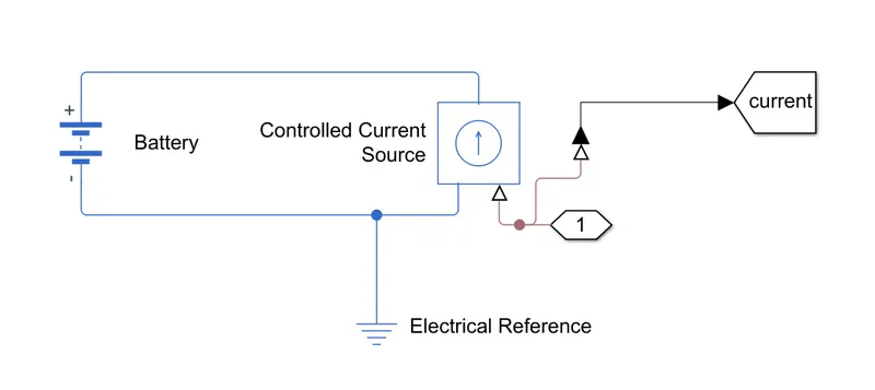
- Battery block
This battery block represents a simple battery model. The block models the battery as a series internal resistance and a constant voltage source.
The block and its parameters are shown below,
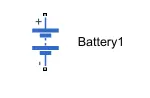
All other parameter sections are kept at default values.
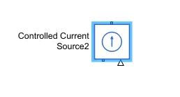
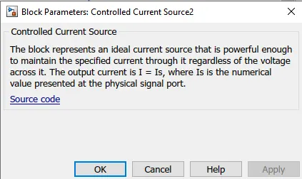
- Controlled current source block
This block gives a constant current output regardless of the voltage across it.
The block and its parameters are shown below,
- Goto block
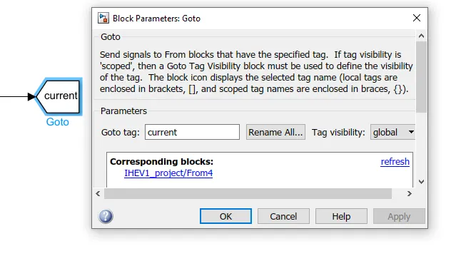
It is used to pass values to the ‘From block’ so that this value can be accessed from anywhere in the Simulink diagram. This input can be a real or complex valued signal or vector of any data type. This ‘From block’ and ‘Goto block’ allows us to pass a signal from one block to another without actually connecting them.
The block diagram & parameters of Goto block is shown below,
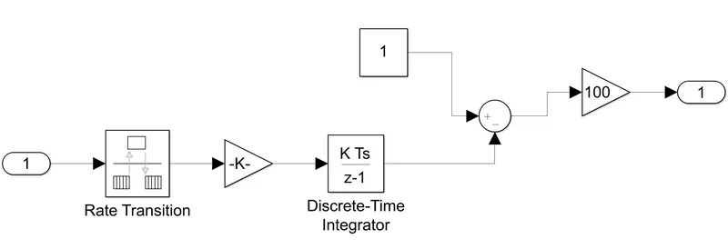
- State of charge calculation subsystem
The block diagram of the subsystem is as shown below,
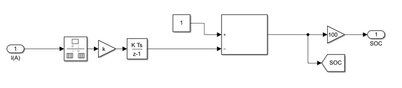
The input for this is from the current sensor.
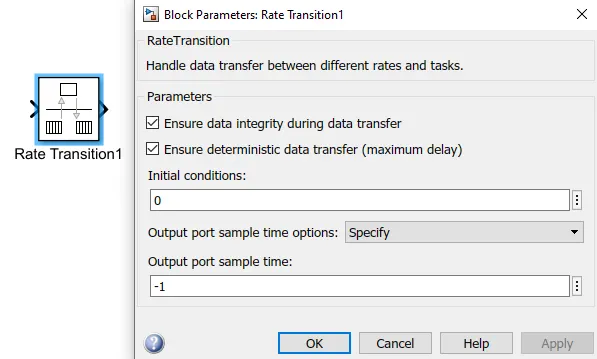
Now this is connected to the rate transition block. This handles the transfer of data between blocks operating at different rates. The block and its parameters are shown below,
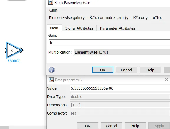
Then a gain block is connected to it. This gain will multiply the value of k=1A⋅sec , where A⋅sec is the ampere second value of the battery.
In this case the battery capacity is in A⋅hr , which is ampere hour.
To convert ,
A⋅sec=A⋅hr⋅(3600)
Then to add all these values with respect to time , we have used a Discrete-time integrator. This block will accumulate the input signal. The block and its parameters are shown below,
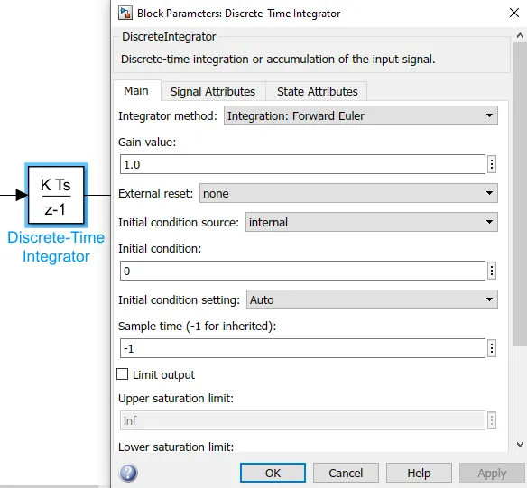
Now this summed value is subtracted from 1, which will give us the remaining State of Charge. To convert this to percentage, we have multiplied by 100 using another gain block.
Also, a Goto block is used here to get SOC values.
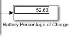
The output from this subsystem is connected to a display block, which will display the Battery Percentage as shown below,
- Vehicle body subsystem
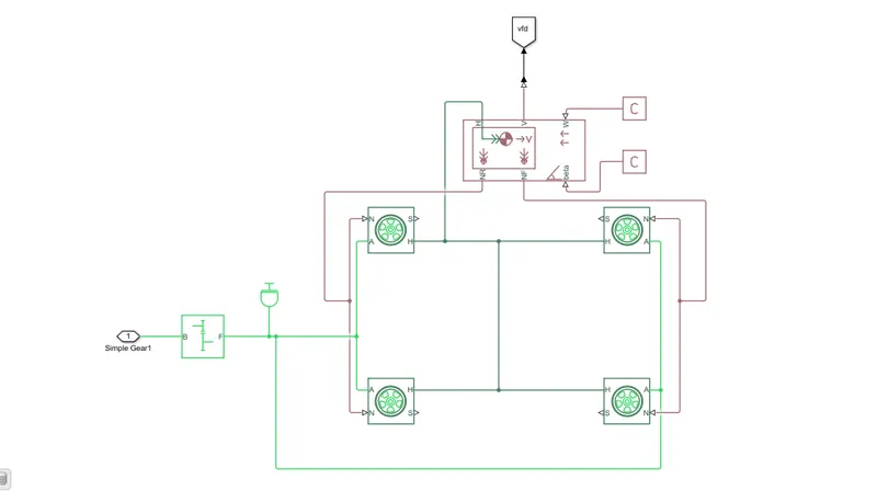
This subsystem represents the body of a vehicle. The block diagram for this subsystem is shown below,
https://drive.google.com/file/d/1Ej96yXs3Scyw1QBMh--1J7gNgmmYD_tW/view?usp=sharing
The input to this subsystem is the mechanical rotational conserving port of the DC motor block.
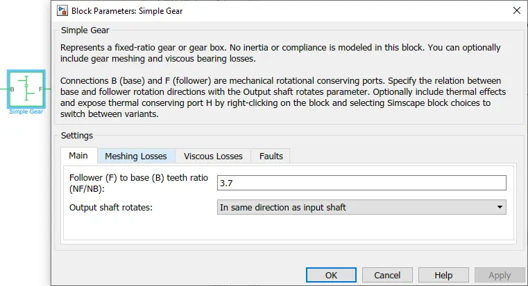
This is connected to the single speed gear box of gear ratio 3.7. This block and its parameters are shown below,
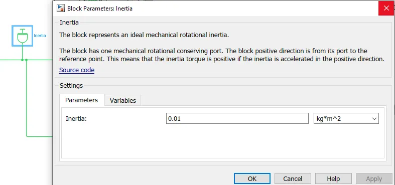
The inertia acting on the shafts is given using a Inertia block. This block and its parameters are shown below,
Now the simple gear is connected to all four wheels, representing an All-wheel Drive vehicle. The tires are represented using tire (magic formula) block. This block and its parameters are shown below,
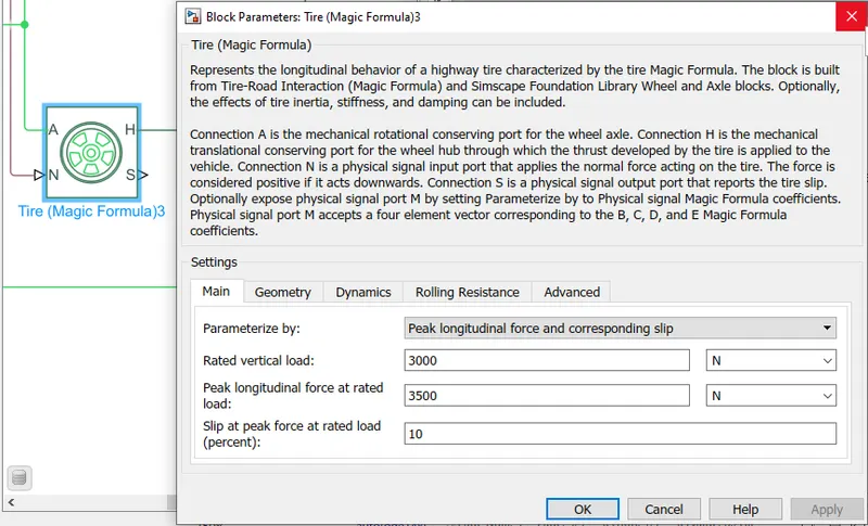
The simple gear is connected to the axle port of the tire block.
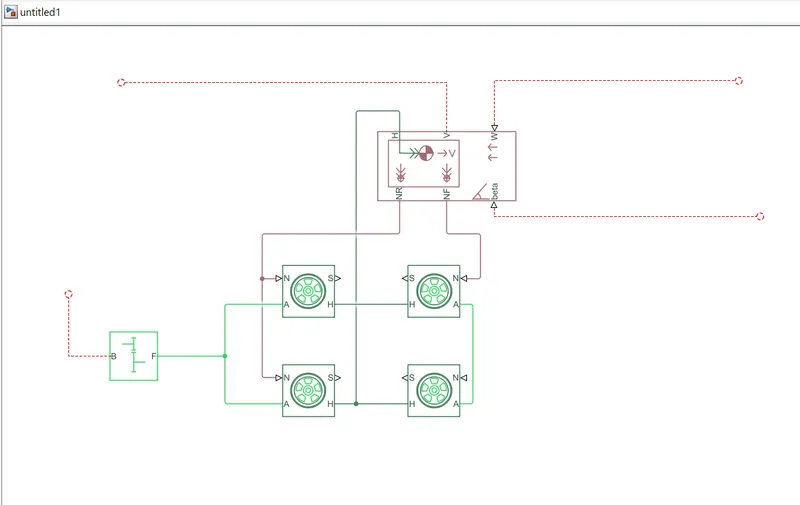
Now to represent the vehicle body we have used the vehicle body block . This block and its parameters are shown below,
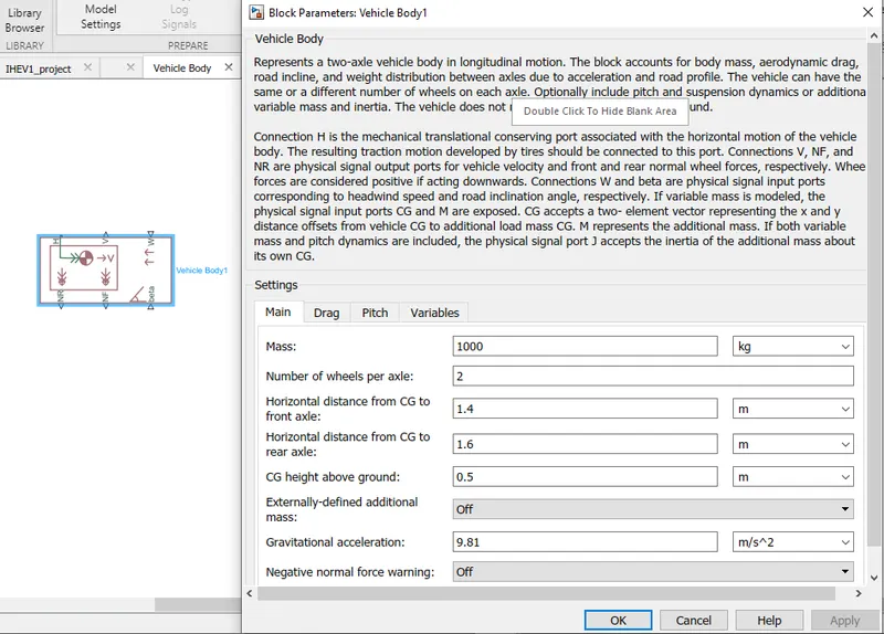

Now to the front and rear normal forces ports represented by NF & NR respectively of the vehicle body we have connected the four tire. Two at NF and two at NR ports. This represents the front 2 tires and the rear 2 tires.
Also, the mechanical translational conserving port for the wheel hub represented by ‘H’ in tire block is connected to the port ‘H’ in the vehicle body block which represents the mechanical translational conserving port associated with the horizontal motion of the vehicle body.
To the gradient and wind speed ports of the vehicle body block, we have connected physical signal constant block.
The output from the vehicle body is the velocity of the vehicle in m/s. This output is connected to the Goto block with tag ‘vfd’.
Now coming back to the longitudinal driver block, the VelFdbk input to this block is given using the ‘From block ‘with tag ‘vfd’. This is the output from the vehicle body block.
Where can Matlab be used in EV
Designing an EV is an elaborate process as it involves a lot of different sub-systems, and in order to maximize the performance of an EV, a lot of parameters and testing need to be done. The MATLAB Simulink and Sims cape provide features to design and simulate essential Electric Vehicle use cases. The 7 most important use cases for Matlab are:
- Tune regenerative braking algorithms
- Explore electric powertrain architectures
- Modify a suspension design
- Optimize vehicle performance
- Develop active chassis controls
- Validate ADAS algorithms
- Test using hardware-in-the-loop (HIL)
PROCEDURE :
- SoC is the percentage or level of battery presents after certain travel or consumption of battery charge by the vehicle.
- In the designed vehicle battery charge or SOC is calculated by the giving it to the rate transition and then to gain where 1/(nominal battery capacity) then to a discrete-time integrator and it will get minus from the 1 as it is considered a 100% of battery and it is multiplied with 100 to get percentage of battery.
- The majority of blocks are Rate transition,discrete time intergrator,sum,gain block.
Multiport switch :
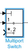
- here first input we use as a constant block so other block will according to it,and it will generate input signal corresponding to multiport switch output no.
- The inputs are numbered top to bottom (or left to right). The first input port is the control port. The other input ports are data ports.
Driver control block :
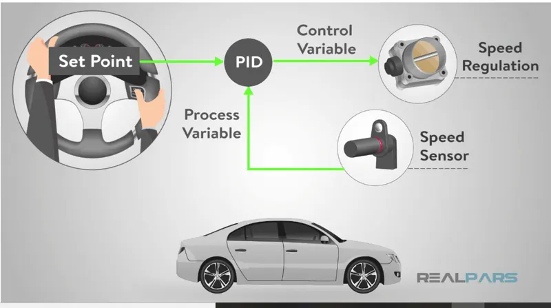
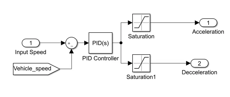
- The driver controller block is responsible for giving the acceleration input and deceleration input according to the input drive cycle. Even with all the parameters and other factors are perfect, if this controller block fails then it will not give the desired acceleration and deceleration inputs to the Electrical Drive System and then the vehicle will fail to follow the drive cycle.
- So,we have a clear idea that how important the block is and it needs to be work perfectly to have our desired vehicle tracking outputs.
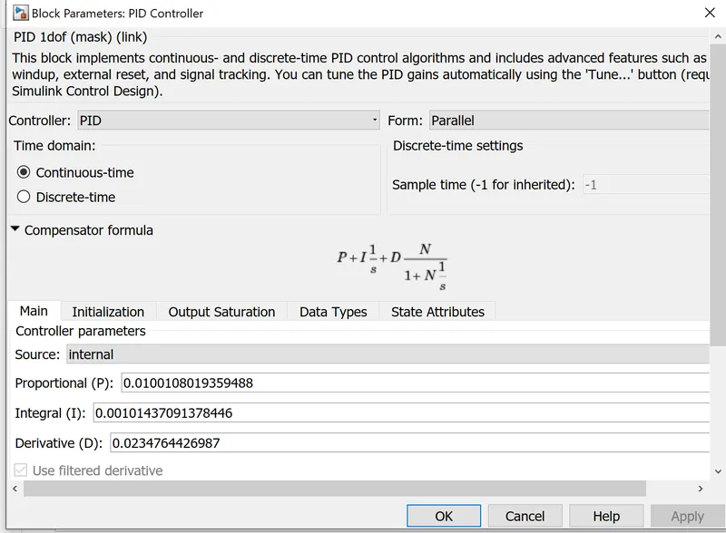
- Now, to achieve good control over these inputs, we have to have correct values for any controller parameter gains to get the desired response. The controller can be PI, PID and it can be represented in many ways. For this process to employ the controller the PID controller Method choosen.
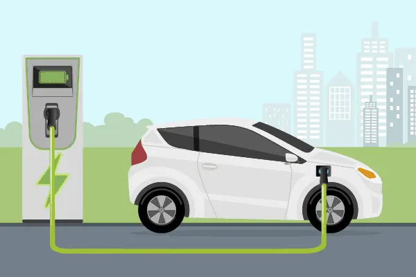
Electric cars function by plugging into a charge point and taking electricity from the grid. They store the electricity in rechargeable batteries that power an electric motor, which turns the wheels. Electric cars accelerate faster than vehicles with traditional fuel engines – so they feel lighter to drive.
* How does Charging work?
You can charge an electric vehicle by plugging it into a public charging station or into a home charger. There is plenty of charging to stay fully charged while you're out and about. But to get the best deal for home charging, it's important to get the right EV electric tariff so you can spend less money charging and save more on your bill.
* EV and their ranges
How far you can travel on a full charge depends on the vehicle. Each model has a different range, battery size and efficiency. The perfect electric car for you will be the one you can use for your normal journeys without having to stop and charge up halfway through.
* What types of electric cars are there?
There are a few different types of electric vehicles (EV). Some run purely on electricity, these are called pure electric vehicles. And some can also be run on petrol or diesel, these are called hybrid electric vehicles.
- Plug-in electric - This means the car runs purely on electricity and gets all its power when it's plugged in to charge. This type doesn't need petrol or diesel to run so doesn't produce any emissions like traditional cars.
- Plug-in hybrid - These cars mainly run on electricity but also have a traditional fuel engine so you can use petrol or diesel too if they run out of charge. When running on fuel, these cars will produce emissions but when they're running on electricity, they won't. Plug-in hybrids can be plugged into an electricity source to recharge their battery.
- Hybrid-electric - These run mainly on fuel like petrol or diesel but also have an electric battery too, which is recharged through regenerative braking. These let you switch between using your fuel engine and using 'EV' mode at the touch of a button. These cars cannot be plugged into an electricity source and rely on petrol or diesel for energy.
* What are the inner parts of EV?
EVs have 90% fewer moving parts than an ICE (Internal Combustion Engine) car. Here's a breakdown of the parts that keep an EV moving:
- Electric Engine/Motor - Provides power to rotate the wheels. It can be DC/AC type, however, AC motors are more common.
- Inverter - Converts the electric current in the form of Direct Current (DC) into Alternating Current (AC)
- Drivetrain - EVs have a single-speed transmission that sends power from the motor to the wheels.
- Batteries - Store the electricity required to run an EV. The higher the kW of the battery, the higher the range.
- Charging - Plug into an outlet or EV charging point to charge your battery.
* EV Batteries
Kilowatts (kW) is a unit of power (how much energy a device needs to work). A kilowatt-hour(kWh) is a unit of energy (it shows how much energy has been used), e.g. a 100-watt lightbulb uses 0.1 kilowatts each hour. An average home consumes 3,100 kWh of energy a year. An electric car consumes an average of 2,000 kWh of energy a year.
* How to charge an EV?
You can charge an electric vehicle either by plugging it into a socket or by plugging into a charging unit. There are plenty of charging stations around the UK to stay fully charged while you're out and about. There are three types of chargers:
Three-pin plug - a standard three-pin plug that you can connect to any 13 amp socket.
Socketed - a charge point where you can connect either a Type 1 or Type 2 cable.
Tethered - a charge point with a cable attached with either a Type 1 or Type 2 connector.
* How long does it take to charge an electric car?
There are also three EV charging speeds:
- Slow - typically rated up to 3kW. Often used to charge overnight or at the workplace. Charging time: 8-10 hours.
- Fast - typically rated at either 7Kw or 22kW. Tend to be installed in car parks, supermarkets, leisure centers and houses with off-street parking. Charging time: 3-4 hours.
- Rapid - typically rated from 43 kW. Only compatible with EVs that have the rapid charging capability. Charging time: 30-60 minutes.
# THEORY
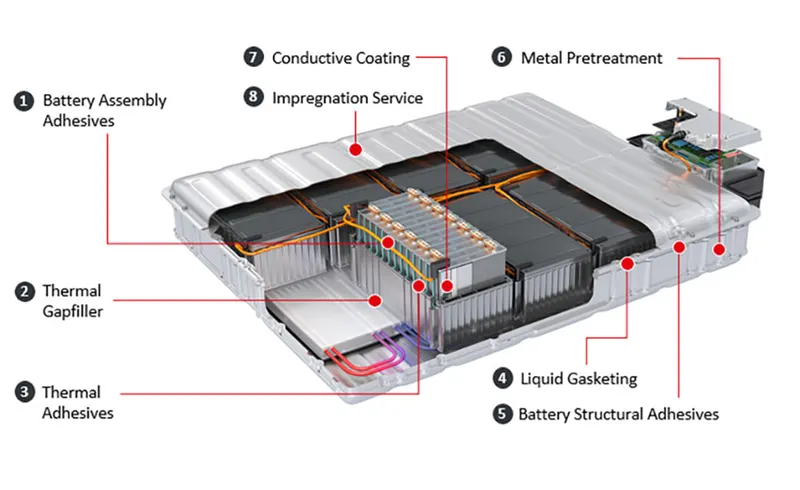
Battery:
- Most electric vehicles use lithium-ion batteries (Li-Ions or LIBs). Lithium-ion batteries have a higher energy density, longer life span and higher power density than most other practical batteries. Complicating factors include safety, durability, thermal breakdown and cost. Li-ion batteries should be used within the safe temperature and voltage ranges in order to operate safely and efficiently.
- Increasing the battery's lifespan decreases effective costs. One technique is to operate a subset of the battery cells at a time and switching these subsets.
- In the past, nickel-metal hydride battery batteries were used in some electric cars, such as those made by General Motors. These battery types are considered outdated due to their tendencies to self-discharge in the heat. Furthermore, a patent for this type of battery was held by Chevron, which created a problem for their widespread development. These factors, coupled with their high cost, have led to lithium-ion batteries leading as the predominant battery for EVs.
- The prices of lithium-ion batteries are constantly decreasing, contributing to a reduction in the price of electric vehicles.
Electrical Motor:
- The power of a vehicle's electric motor, as in other machines, is measured in kilowatts (kW). Electric motors can deliver their maximum torque over a wide RPM range.
- This means that the performance of a vehicle with a 100 kW electric motor exceeds that of a vehicle with a 100 kW internal combustion engine, which can only deliver its maximum torque within a limited range of engine speed.
- The efficiency of charging varies considerably depending on the type of charger, and energy is lost during the process of converting the electrical energy to mechanical energy.
- Usually, direct current (DC) electricity is fed into a DC/AC inverter where it is converted to alternating current (AC) electricity and this AC electricity is connected to a 3-phase AC motor.
- For electric trains, forklift trucks, and some electric cars, DC motors are often used. In some cases, universal motors are used, and then AC or DC may be employed. In recent production vehicles, various motor types have been implemented; for instance, induction motors within Tesla Motor vehicles and permanent magnet machines in the Nissan Leaf and Chevrolet Bolt
Motor Controller:
- The motor controller of an electric car administers its complete operation and the distribution of its power at any given moment. It acts as a floodgate between the motor and batteries.
- It helps monitor and regulates all key performance indications such as the vehicle's operator, motor, battery, and accelerator pedal. It has a microprocessor that can limit or redirect current.
- It is used to either improve the mechanical performance of the car or suit the operator's driving style. There are also more refined controllers which are capable of greater accuracy and thus, higher efficiency.
# SIMULATION
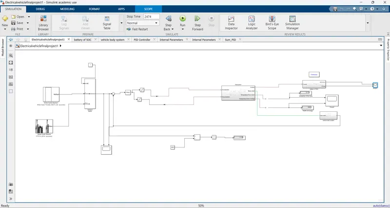
THE LINK SHOW THE SIMULINK MODEL
https://drive.google.com/file/d/1_NA5ldyiH3ZCGLAVhwJdYFKlx4y0O9iG/view?usp=sharing
The electric vehicle is constructed in a manner of four step-by-step processes, so to design of the EV model always starts within the order:
1) construction of vehicle body design
2)Selecting the motor
3)Suitable control unit for motor
4)Source of energy for motors
1) Construction of vehicle body design
- Motor will produce the rotational output which will give to the vehicle body and transmission system. The rotational output is taken by the gear system here to maintain the constant speed throughout the transmission without any loss in speed from the motor to tires.
- Below is a diagram that is how it is inside the vehicle body and transmission system and in the main design, it is referred just only as a transmission system. Here I created a Rear-wheel drive transmission system.
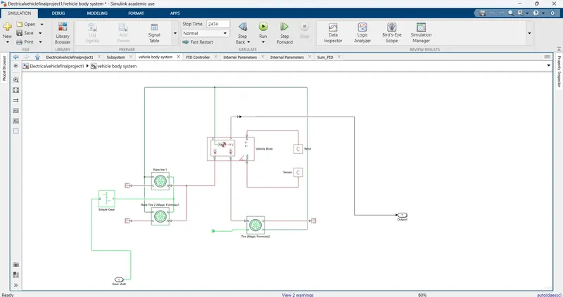
- The gear output is given to axels of Rear tires in the circuit it is shown that gear is connected to Rear wheels and the front tire is free to rotational motion, thus the vehicle moves forward. N is the normal force caused by the tires and it is given to the vehicle body normal force port.
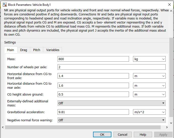
- The vehicle body has an H-Hub, S- Tire slip, and N-Normal force. As axel connection, wind velocity, and inclination angle. The tires hub is connected as a common node to the vehicle body.
- The vehicle body wind velocity is connected to a constant block and the beta-inclination angle is connected to another constant block where we can assign wind velocity and inclination angle as per requirement. Velocity is the output port where we can get at which speed the vehicle is moving. The velocity is taken out to get the distance travelled and state of charge
* Vehicle Body Parameters
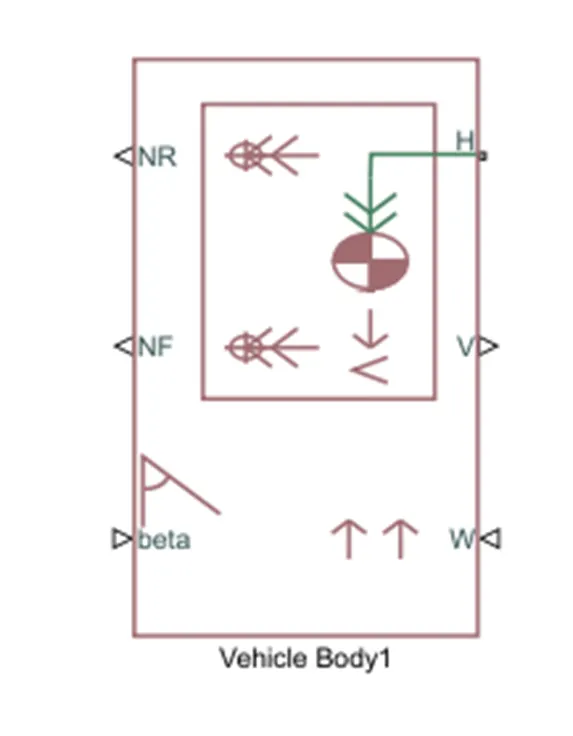
Input Ports:
W=Wind Velocity in m/s
beta=Grade angle in radians
Output Ports:
V=Velocity in m/s
NR=Normal force on Rear Axle (N)
NF=Normal Force on Front Axle (N)
- Vehicle body mass, Centre of gravity distance values and aerodynamic drag variables are modified.
- Pitch dynamics are kept ON with other variable values as default values.
- Represents the longitudinal behavior of a highway tire characterized by the tire Magic Formula. The block is built from Tire-Road Interaction (Magic Formula) and Simscape Foundation Library Wheel and Axle blocks. Optionally, the effects of tire inertia, stiffness and damping can be included.
- Represents a two-axle vehicle body in motion.
- Accounts for body mass, and aerodynamic drag. grade, externally defined mass and centre of gravity of the vehicle body.
- This block basically represents a two-axle vehicle body in longitudinal motion. The block accounts for - body mass, aerodynamic drag, road incline, weight distribution between axles due to acceleration road profile.
- Here, connection H is the mechanical translational conserving port hub.
- NF & NR correspond to the output ports for normal reaction forces on the front axle and rear axle wheels respectively.
- Connection V represents the actual output translational velocity of the vehicle.
- beta is the road inclination angle & W corresponds to the headwind speed (headwind direction opposite to that of the vehicle).
* Tire:
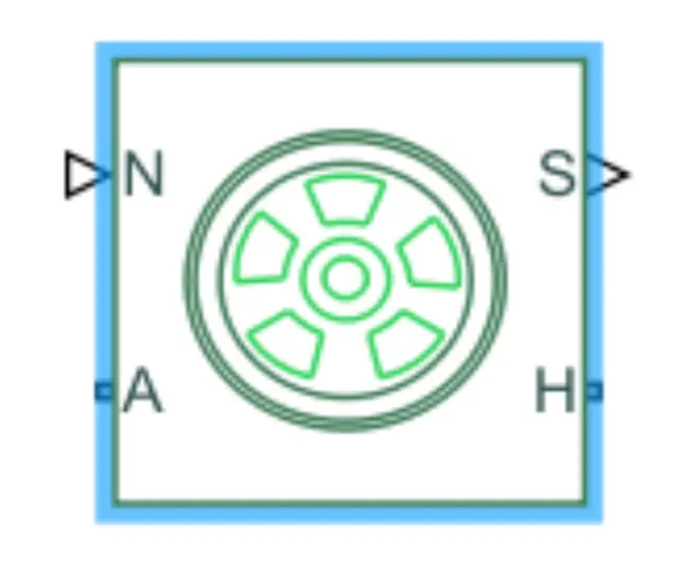
- The vehicle is assumed to be front axle is driven (4 wheels- 2 on each axle).
- The wheels are modeled using simple Tire (Magic formula) Simulink blocks.
- The block can model tire dynamics under constant or variable contact surface conditions.
- Input Port: N=Normal force acting on the tire, positive when force is acting downwards/towards the contact surface.
- Output Port: S=Slip value is relative to tire and surface of contact.
- Conserving Ports: H=represents wheel hub which transmits thrust generated by the wheel to the body of the vehicle.
- A=represents the axle on which the tires are mounted.
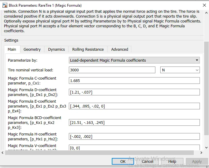
- The tires are parameterized by Peak longitudinal force and corresponding slip
- The other block parameters such as rated vertical load, peak longitudinal force at rated load and slip at peak force at rated load are kept with their default values.
Gear:
- A simple gear block is used to connect the motor to the rear axle of the vehicle.
- It represents the gearbox that connects the input shaft to the base gear and output from the follower gear.
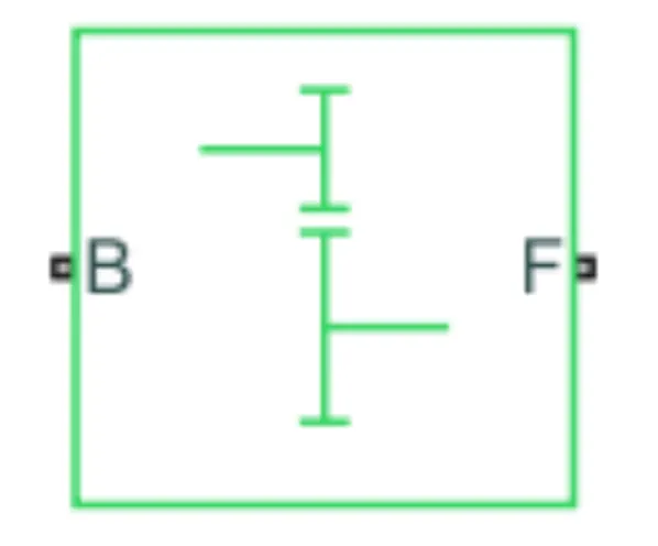
- Conserving Ports: B=port associated with an input shaft (motor shaft)
F=port associated with the output shaft (axle/ differential)
- Gear ratio and output direction are modified. Meshing loss is kept constant and gear is having a constant efficiency throughout the simulation.
- Viscous losses and faults are kept at default conditions
- Here teeth Ratio given is 10,in same direction of the shaft
2) Selecting the motor
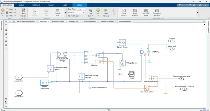
https://drive.google.com/file/d/1LSt8mqXOgKjS2Fj2RX2WIMKMiFwhkmmV/view?usp=sharing
The Motor controller will get input from the longitudinal driver. Its tasks are to control the speed of the motor and drive according to the input of the driver.
- Majorly motor controlled we designed had two main parts named PWM voltage generator and H-Bridge Input 1 is getting from the acceleration of a longitudinal driver and it is given to a controlled voltage source block where it is input to the controlled PWM voltage will generate a PWM signal in such a way that H-bridge will generate the required voltage to operate the DC motor for the given driver input
- PWM voltage block negative reference and REF are grounded and REF of H bridge respectively. H-bridge is a motor controller that has IGBT components aligned in the shape of H and will operate only two at a time respectively to the input of the signal from the PWM block.
- When deceleration occurs this H-bridge will give an output from the positive and negative terminals of it. These negative & positive terminals are later connected to the DC motor and battery. All these components are the simscape electrical components so they need a connection to the solver configuration block which helps to solve the simulation.
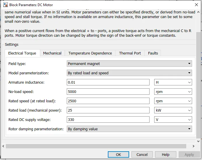
* D.C Motor:
This is the DC Motor that would give rotational power to the wheels and become the sole power generation source.
The DC Motors terminals are connected as mentioned below.
+ =Electrical signal to the motor Positive Terminal
- =Electrical signal to the motor Negative Terminal
R=Casing of the Motor connected with the Mechanical Rotational Reference Block
C=Rotor Case connected to the Mechanical Rotational reference
The parameter considered is, The Armature inductance is as default, varied the changes in the No-Load Speed 6000 rpm, the rated speed 4000 rpm, the Rated Load at 15kW, and the Rated DC Supply Voltage 300 V. All other parameters are as default.
* Temperature Sensor
- Temperature Sensor is used to measure the temperature of the H-Bridge and Motor.
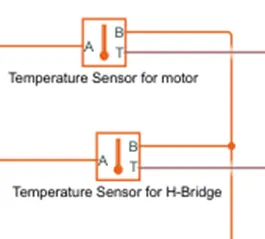
- This block measures temperature in a thermal network. There is no heat flow through the sensor. The physical signal port T reports the temperature difference across the sensor.
- The measurement is positive when the temperature at port A is greater than temperature at port B.
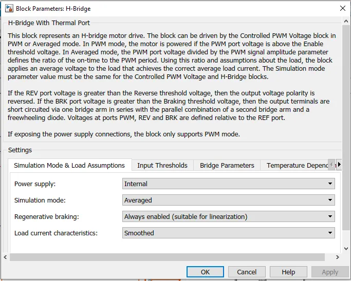
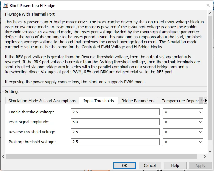
* H Bridge
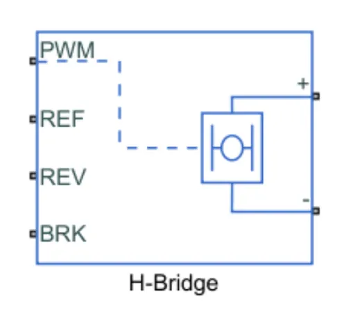
- This block represents an H-bridge motor drive. The block can be driven by the Controlled PWM Voltage block in PWM or Averaged mode.
- In PWM mode, the motor is powered if the PWM port voltage is above the Enable threshold voltage in Averaged mode.
- The PWM port voltage divided by the PWM signal amplitude parameter defines the ratio of the on-time to the PWM period.
- Using this ratio and assumptions about the load, the block applies an average voltage to the load that achieves the correct average load current.
- The Simulation mode parameter value must be the same for the Controlled PWM Voltage and H Bridge blocks.
The H-Bridge helps in controlling the power that is input according to the requirement. The output provided is converted voltage as per the controlled parameters.
* Controlled PWM Voltage:
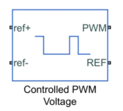
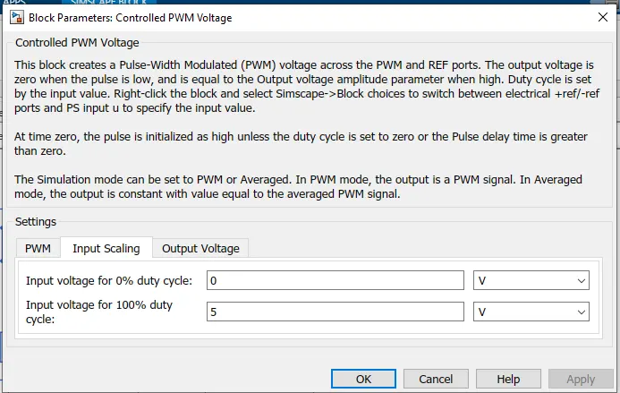
The Controlled PWM Voltage Block helps in keeping the Modulated Pulses as per the required pulses. So that the operations happen smoothly and higher variations are not observed.
The Ports are connected as follows.
PWM=PWM connected directly to the H-Block
REF=REF connected directly to the H-Block
ref+ = Reference Positive connected with Driver Model ith the Acceleration Commands from the
ref- =Reference Negative connected with the Deceleration Commands from the Driver Model
Note: The parameters are set as default.
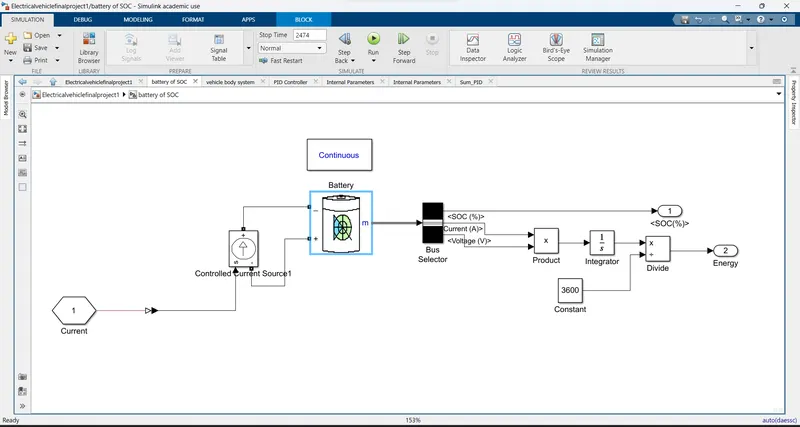
3)Battery and SOC System
https://drive.google.com/file/d/1ixmXIDqSZegYOLeYQVr4yAm_hn9ww9ve/view?usp=sharing
* Battery
Implements a generic battery model for most popular battery types. Temperature and ageing (due to cycling) effects can be specified for Lithium-Ion battery type.
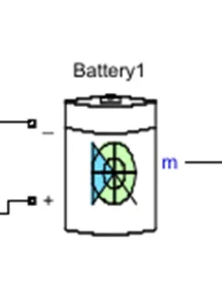
- The battery is required to power the controller and motor. The controller uses the battery power according to produce the input given by the motor to obtain maximum speed.
- The battery is also used to power every electrical component in the vehicle.
- The Battery block implements a generic dynamic model that represents the most popular types of rechargeable batteries.
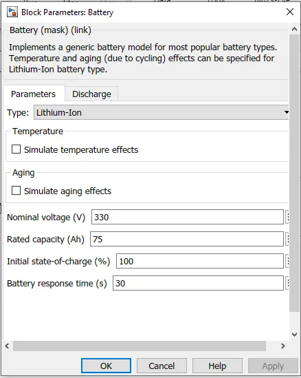
The battery has two-stage one is charging and another one is discharging state.
The battery is of 75Ah capacity.
The Nominal voltage of the battery is 330 V
Initial SoC is 100%
The battery as a series internal resistance plus a charge-dependent voltage source
defined by: 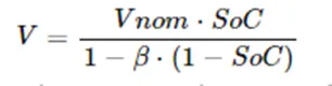
where SoC is the state of charge and Vnom is the nominal voltage.
Coefficient beta is calculated to satisfy a user-defined data point [AH1,VI].
- The battery has a positive and negative terminal which is given the voltage-controlled source where the battery consumption is controlled by the motor controller and then it is given to the SOC block
* Battery State of Charge:
- SoC is the percentage or level of battery presents after certain travel or consumption of battery charge by the vehicle.
- In the designed vehicle battery charge or SOC is calculated by giving it to the rate transition and then to gain where 1/inominal battery capacity) then to a discrete-time integrator and it will get minus from the 1 as it is considered a 100% of battery and it is multiplied with 100 to get a percentage of battery.
- The majority of blocks are simscape blocks were physical to Simulink converter is used to convert the physical signal from simscape block to Simulink signal
* Controlled Current Source
- The Controlled Current Source block converts the Simulink input signal into an equivalent current source. The generated current is driven by the input signal of the block. The positive current direction is as shown by the arrow in the block icon.
- We can initialize the Controlled Current Source block with a specific AC or DC current. if we want to start the simulation in steady-state the block input must be connected to a signal starting as a sinusoidal or DC waveform corresponding to the initial values
- Double click controlled current source and from the drop-down menu of measurement select current.
- Signal output will connect with scope by adding the current signal to it. (+) the terminal will connect with the battery (-) terminal.
* BUS Selector
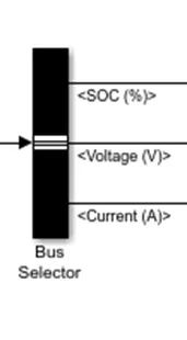
- The Bus Selector block outputs the signals you select from the input bus The block can output the selected elements separately or in a new virtual bus.
- Here just we have mange the output and connect it with different Scope Block.
* PowerGUI
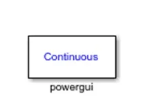
- The powerful block allows us to choose one of these methods to solve.
- Continuous, which uses a variable-step solver from Simulink your circuit
- Discretization of the electrical system for a solution at fixed time steps. Continuous or discrete phasor solution
- The powerful block also opens tools for steady-state and simulation results analysis and for advanced parameter design
4)Source of energy for motors
*PID controller
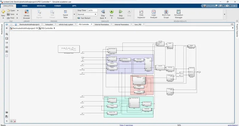
https://drive.google.com/file/d/1878t1zJx4JMGw4eU9Eara2IwFKMbY2xL/view?usp=sharing
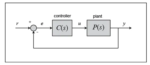
The output of a PID controller, which is equal to the control input to the plant, is calculated in the time domain from the feedback error as follows:
First, let's take a look at how the PID controller works in a closed-loop system using the schematic shown above. The variable () represents the tracking error, the difference between the desired output () and the actual output (). This error signal () is fed to the PID controller, and the controller computes both the derivative and the integral of this error signal with respect to time. The control signal () to the plant is equal to the proportional gain () times the magnitude of the error plus the integral gain () times the integral of the error plus the derivative gain () times the derivative of the error.
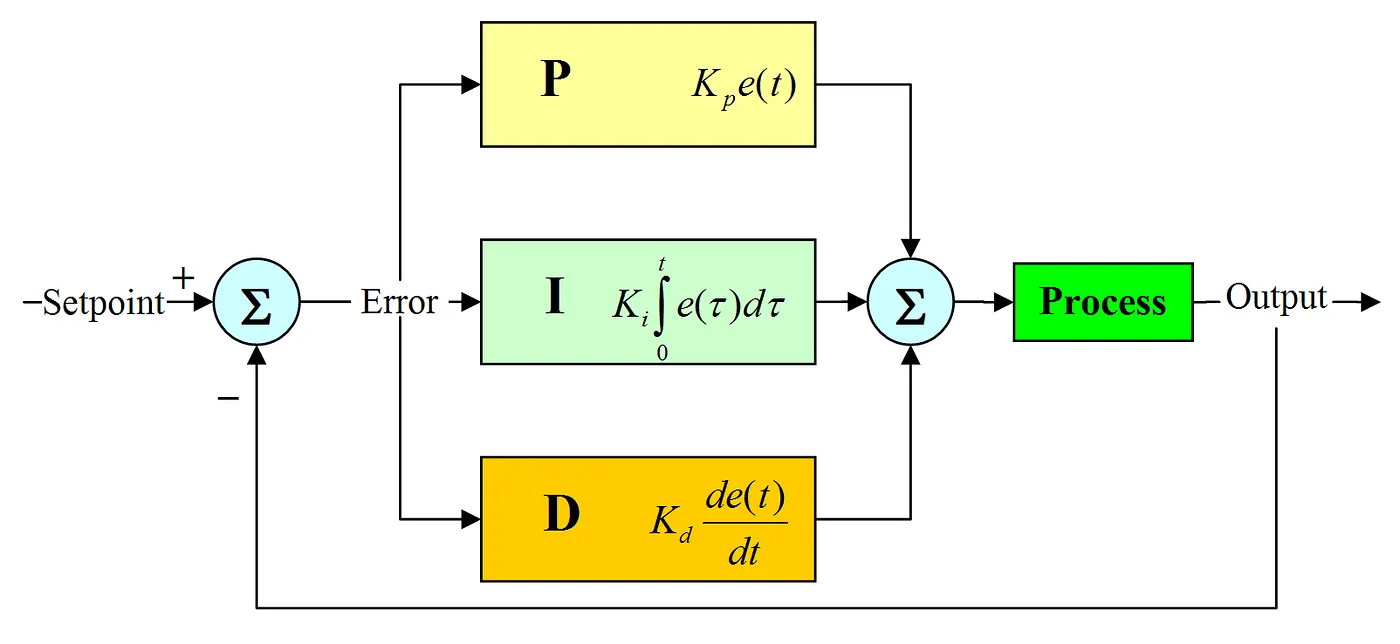
This control signal () is fed to the plant and the new output () is obtained. The new output () is then fed back and compared to the reference to find the new error signal (). The controller takes this new error signal and computes an update of the control input. This process continues while the controller is in effect.
The transfer function of a PID controller is found by taking the Laplace transform of Equation .
where = proportional gain, = integral gain, and = derivative gain.
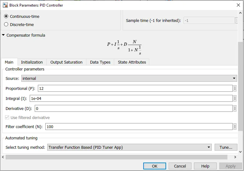
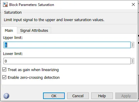
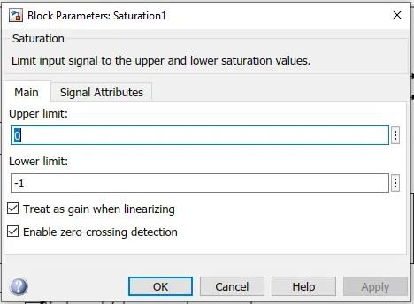
* Reference Velocity (Drive Cycle):
1) FTP75 (2474 seconds)
- The Drive Cycle Source block is used to provide the reference speed for the simulation.
- It generates a standard or user-specified longitudinal drive cycle.
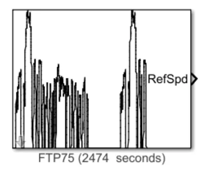
Generates a standard or user-specified longitudinal drive cycle.
The block output is the vehicle longitudinal speed.
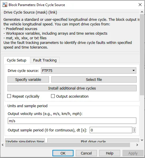
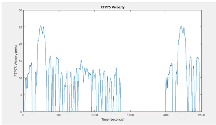
we can import drive cycles from:
# Predefined sources
# Workspace variables, including arrays and time series objects
# mat, Xls, xlsx, or txt files
Use the fault tracking parameters to identify drive cycle faults within the specified speed and time tolerances
2) Wide Open Throttle (WOT):
Wide-open throttle or wide-open throttle (WOT), also called full throttle, is the fully opened state of throttle on an engine (internal combustion engine or steam engine)
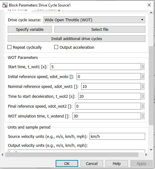
All 2 Drive cycles are controlled by the controller provided above by constant through Multi-part switch.
# SIMULATION RESULTS
1) For FTP75 Drive Cycle:
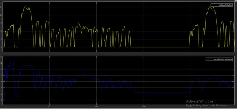
https://drive.google.com/file/d/11sJY-d7vN-Jen50_EPwgPb859zA8Q80V/view?usp=sharing
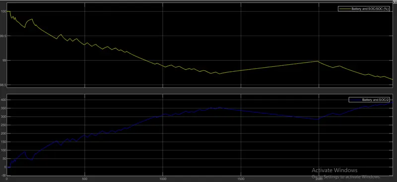 \
\
https://drive.google.com/file/d/1_9dnLrI0A0zmmgByWkIT_p0uv0rsDnqZ/view?usp=sharing
- By running the Vehicle with F1P75 Drive cycle for 2474 see the distance travelled is 3.328 km
- The actual Speed is approximately followed the 80% of reference Drive cycle.
- Initially the battery is 100% charged, after travelling this much distance its battery state is about 98.5 percentage
- Its clear from the graph that battery is discharged during acceleration and charged during deceleration.
- The Temperature of Motor is increased to 400°C.
- The Temperature of Controller is 490°C.
2) WOT Drive cycle
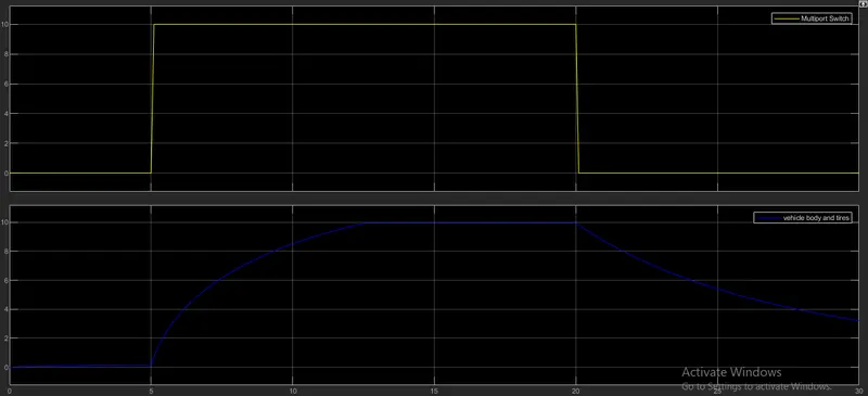
https://drive.google.com/file/d/1hS1Xdv03QKyv4vCa_g1ntAmPVfbkiJOE/view?usp=sharing
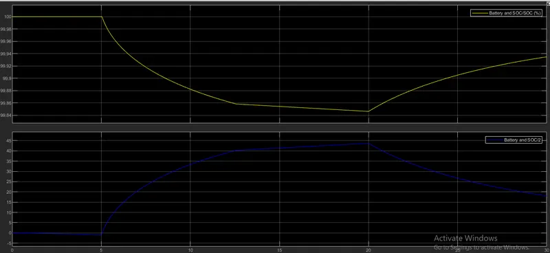
https://drive.google.com/file/d/1025rU95Zws5mDJI3Z4QJNJ6yG87MT_XY/view?usp=sharing
- By running the Vehicle with WOT Drive cycle for 30 sec. the distance travelled is 0.125km
- The actual Speed is approximately followed the 80% of the reference Drive cycle.
- The SoC% of the battery is reduced to 99.8% at 20 th sec and after that the battery get charged by back EMF.
- It's clear from the graph that battery is discharged during acceleration and charged during deceleration.
- The Temperature of the Motor is increased to 307°C.
- The Temperature of the Controller is 470°C.
# CONCLUSION
The temperature of Motor and controller is controlled to achieve vehicle speed is near to reference speeds. Since I haven't used any cooling system in the model. In the real-time application, the motor temperature is less than 100 C. In the real-time application, the motor, battery & controller temperature is controlled by air cooling. Hence, the temperature of these components is not increased to this extent.
Created a MATLAB model of an Electric car (four-wheel passenger vehicle) by using Li-ion battery, PM Brushed DC Motor. Determined the variations of Temperature of Motor and controller, SoC% and Energy consumed by the by vehicle for all the three Reference Drive cycles (.e: FTP75, WOT). This Battery powered car will be the most popular mode of transport in the future.