Week-6 Challenge: EV Drivetrain
Aim:
- To get to know the types of converters used in HEV and EV vehicles.
- To find the speed using torque-speed relation.
- To get to know about induction and DC brushless motors.
Objectives:
- To get information on converters for HEV and EV vehicles.
- Find the speed using torque-speed expression. -
- Try to find the best options for motors for HEV or EV vehicles.
1. Which types of power converter circuits are employed in an electric and hybrid electric vehicle?
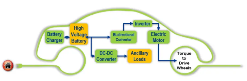
A motor drive consists of a power converter and the controller. The power electronic converter handles the flow of bulk power from the source to the motor input terminals. The controller processes the command input and the feedback information to generate the switching signals for power converter semiconductor switches. - The power converter can be a DC drive supplying a CD motor or an AC drive supplying an AC motor. - A DC/DC converter in its basic form converts unregulated DC input voltage at a certain level to regulated DC output voltage at a different level with very high conversion efficiency. These are operated at very high frequency. The switches are turned ON and OFF by pulse width modulation (PWM). - The power converter is made of high power fast-acting semiconductors devices, such as a bipolar junction transistor. There are some other transistors such as MOSFET, IGBT, SCR, GTO, MCT. These devices are used as on-off electronics switch to convert the fixed supply voltage into a variable voltage and variable frequency supply. - All these devices have a control input gate or base through which the devices are turned on and off as per the command generated by the controller.
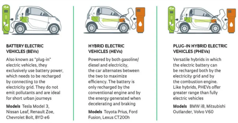
Hybrid Electric vehicle:
• Hybrid Electric Vehicles, or HEVS, have both a gas-powered engine and an electric motor to drive the car. • All energy for the battery is gained through regenerative braking, which recoups otherwise lost energy in braking to assist the gasoline engine during acceleration. • In a traditional internal combustion engine vehicle, this braking energy is normally lost as heat in the brake pads and rotors • Regular hybrids cannot plug into the grid to recharge and cannot charge with EV go.
Plug-in Hybrid Electric vehicle:
• Plug-in Hybrid Electric Vehicles, or PHEVs, have both an engine and electric motor to drive the car. • Like regular hybrids, they can recharge their battery through regenerative braking. • They differ from regular hybrids by having a much larger battery, and being able to plug into the grid to recharge. • While regular hybrids can (at low speed) travel 1-2 miles before the gasoline engine turns on, PHEVs can go anywhere from 10-40 miles before their gas engines provide assistance. • Once the all-electric range is depleted, PHEVs act as regular hybrids, and can travel several hundred miles on a tank of gasoline. • All PHEVs can charge at an EV go L2 charger, but most PHEVs are not capable of supporting fast charging
Battery Electric vehicle:
• Battery Electric Vehicles, also called BEVS and more frequently called EVS, are fully electric vehicles with rechargeable batteries and no gasoline engine. • BEVS are zero emissions vehicles, as they do not generate any harmful tailpipe emissions or air pollution hazards caused by traditional gasoline-powered vehicles. • All energy to run the vehicle comes from the battery pack which is recharged from the grid. • Some popular EV models are pictured here and a full list of available fast charging EV models is available in the chart above.
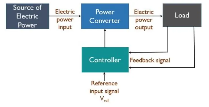
The block diagram of a power electronic converter is shown in figure above. It consists of an electrical energy source, power electronic circuit, a control circuit and an electric load. This converter changes one form of electrical energy to other form of electrical energy. The power electronic circuit consists of both power part and control part Power part transfers the energy from source to load and it consists of power electronic switches (SCR or TRIAC), transformers, electric choke, capacitors, fuses and sometimes resistors.
The control circuit or block regulates the elements in the power part of the converter. This block is built with a complex low power electronic circuit that consists of either analog or digital circuit assembly. Power electronic converters perform various basic power conversion functions. This converter is a single power conversion stage that can perform any of the functions in AC and DC power conversion systems. Depending on the type of function performed, power electronic converters are categorized into following types.
• AC to DC = Rectifier. It converts AC to unipolar (DC) current
• DC to AC = Inverter. It converts DC to AC of desired frequency and voltage
• DC to DC = Chopper: It converts constant to variable DC or variable DC to constant DC
• AC to AC = Cycloconverter, Matrix converter: It converts AC of desired frequency and/or desired voltage magnitude from a line AC supply.
These types of power electronic converters may be found in a wide variety of applications but among them only three types of power converter circuits are employed in electric and hybrid electric vehicle. The following power converter circuits are discussed below,
• AC to DC Converters or Rectifier:
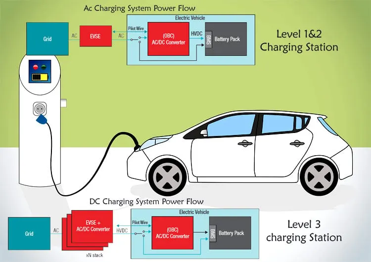
AC to DC converter is also called a rectifier, which converts AC supply from main lines to DC supply for the load. he blocks diagram of an AC to DC converter is shown in figure below. he essential components in this rectifier include transformer, switching unit, filter and a control block.
Here, the transformer adjusts the primary AC source supply to the input of rectifier stage. Usually, it is a step-down
Here, the transformer adjusts the primary AC source supply to the input of rectifier stage. Usually, it is a step-down transformer that reduces the supply voltage to a circuit operating range. The rectifier converts the low voltage AC supply into DC supply. It comprises diode and/or thyristors based on type of rectifier. The output of the rectifier is of pulsed DC and hence it is filtered using filter circuit, which is usually made with a capacitor or a choke. The control block controls the firing angle of thyristors in case of phase-controlled rectifiers. Since the diode is not a controllable device, control block is not needed in case of diode rectifiers.
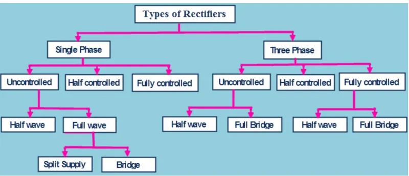
Rectifiers are majorly classified into two types
• Uncontrolled diode rectifiers
• Controlled rectifiers
Uncontrolled Diode Rectifiers This type of rectifier converts AC voltage from mains into a fixed DC voltage. Since the diodes are uncontrollable components (which do not require any triggering), these converters are called as uncontrolled converters as they produce a fixed voltage. The input voltage can be either single phase or three-phase. The diode rectifiers are classified into following types. I. Single Phase half-wave rectifier. -The Single-Phase half-wave rectifier is a type of rectifier that rectifies only half cycle of the waveform. This article describes the half wave rectifier circuit working. The half rectifier consists a step-down transformer, a diode connected to the transformer and a load resistance connected to the cathode end of the diode.
• DC to DC converters:
Many DC operated applications need different levels of DC voltage from a fixed DC source. Some of these applications include subway cars, DC traction systems, control of large DC motors, battery operated vehicles, trolley buses, etc. They require variable DC to produce variable speed, so a power conversion device is needed.
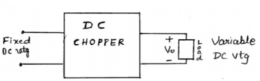
A DC chopper is a static device that converts a fixed input DC voltage to variable DC output or a fixed DC output of different magnitude (which can be lower or higher) than input value. The block diagram of a DC chopper is shown in figure below.
The chopper circuit is connected between DC input source and DC load. This chopper consists of power electronic switching devices such as thyristors which are connected in such a way that they produce required DC voltage to the load.
The output voltage is controlled by adjusting ON time of the thyristor (or switch) which turn changes the width of DC voltage pulse at the output. This method of switching is called as pulse width modulation (PWM) control. The output of the chopper can be less or greater than the input and also it can be fixed or variable. These can be unidirectional or bidirectional devices based on the application it is intended for. DC choppers are mainly used in DC drives, i.e., electric vehicles and hybrid electric vehicles. DC choppers are classified into three basic types based on input and output voltage levels and are discussed below.
I. Step-down Chopper or Buck Converter: A step-down chopper produces an average output voltage lower than the input DC voltage. The circuit for this converter is shown in figure below. Here the switching component is a thyristor that switches the input voltage to the load when it is triggered at particular instants. A diode acts as a freewheeling diode that allows the load current to flow through it when thyristor is turned OFF. If this diode is absent, a high induced EMF in inductance may cause damage to the switching device.
DC to AC Converters or Inverters:
These converters are connected between DC source of fixed input, and variable AC load. Most commonly, these DC to AC converters are called as inverters. An inverter is a static device that converts fixed DC supply voltage to variable AC voltage.
Here the fixed DC voltage is obtained from batteries or by DC link in most power electronic converter. The output of the inverter can be variable/ fixed AC voltage with variable/fixed frequency. This conversion from DC to AC along with variable supply is produced by varying the triggering angle to the thyristors. Most of the thyristors used in inverters are employed with forced commutation technique. These can be single phase or three phase inverter depending on the supply voltage. These converters are mainly divided into two groups. One is PWM based inverters and other multilevel inverters. Further, these are classified voltage source inverter and current source inverter. Each type is subdivided into different types such as PWM, SVPWM, etc. Multilevel inverters are more popular in industrial applications.
The inverters overcome the drawbacks of PWM based inverters.
The other parameters of the electric vehicle are given below, Motor and Controller Parameters:
Rated Armature voltage= 72 V
Rated armature current= 400 A
Ra= 0.50 ohm
KO= 0.7
Volt second Chopper Switching frequency= 400 Hz
The vehicle speed-torque characteristics are given by the below equation

What is EV steady state speed if duty cycle is 70%?
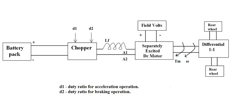
2. An Electric Vehicle's powertrain with 72V battery pack in shown in the diagram below. The duty ratio for acceleration operation is 'd1' and for the braking operation the duty ratio is 'd2'.
Solution:
Vehicle Output Voltage (Vv) = Battery Voltage(V)*Duty Cycle
= 72*0.70
= 50.4 V
So, the vehicle voltage Is 50.4 V
Now, Equation for Vehicle torque is:
Tv=Vv*k ϕ/ Ra - (k ϕ) ^2/Ra.ω.........(1)
Where,
Tv= Vehicle Torque (N-m)
Vv= Vehicle Voltage (Volts)
ω= Steady State speed of Vehicle (rps)
Kϕ= Motor Constant
Ra = Armature Resistance
Substituting all the values in equation 1, we get
TV= (50.4x0.7)/0.5-(0.7) ^2/0.5xω
Tv=70.56-0.98w^2........(2)
Now, the vehicle speed torque characteristics is given as,
Tv=24.7-0.0051w^2........(3)
At Steady State,
Eq (2) = Eq (3) ...... (4)
24.7-0.0051w^2=70.56-0.98w^2
0.0051w^2+0.98w-45.85=0.......(5)
To solve the above eq we have to apply the QUADRATIC EQUATION formula,
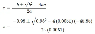
ω= 38.92 rad/sec
The steady-state speed of the vehicle Is 38.92 rad/sec.
3. Develop a mathematical model of a DC Motor for the below equation using Simulink.
ω= V/Kϕ -Ra/Kϕ^2. T
Let us draw a model for the above equation.
Let V = 50.4 Volts
Kϕ= 0.7
Ra= 0.552 and also let consider torque as a linearly increasing signal.
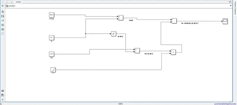
THIS LINK SHOWS THE MATHEMATICAL MODEL OF DC MOTOR SIMULINK https://drive.google.com/file/d/1gfypGIO3IyNcGd-sHuSK1kxNMJwA8eXN/view?usp=sharing
https://drive.google.com/file/d/1xRCWmUAH14mF0j_zVtuKIgOy--IBi7DE/view?usp=sharing
RESULT OUTPUT
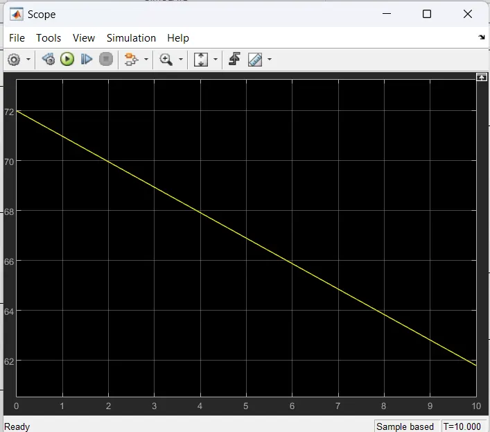
4. Refer to the blog on below topic:
https://www.tesla.com/blog/induction-versus-dc-brushless-motors
Induction Versus DC brushless motors by Wally Rippel, Tesla Explain in brief about author's perspective.
Wally Ripple is a long-time proponent of electric vehicles. Prior to joining Tesla Motors, he was an engineer at AeroVironment, where he helped develop the EV1 for General Motors and was featured in the documentary movie, Who Killed the Electric Car? Wally has also worked for the Jet Propulsion Laboratory on electric vehicle battery research, among other projects. In 1968, as a Caltech undergraduate student, he built an electric car (a converted 1958 Volkswagen microbus) and won the Great Transcontinental Electric Car Race against MIT. In the beginning, the author describes the dominance of Internal Combustion Engines (ICE) in the world of automobile industry. He explains that all engines were similar and it was up to the user to select according to their requirement. Next, the author highlights topics related to EV technology especially related to DC Brushless Motor and Induction Motor.
According to him, DC Brush Motors is replaced by either DC Brushless Motor or Induction Motor. Also, the Lead Acid Battery is replaced by lithium-ion batteries for EVs.He also quoted that there will be the future of both the technology (DC Brushless Motor and Induction Motor) depends upon their demands and uses.
DC Brushless Motor:
With brushless machines, the rotor includes two or more permanent magnets that generate a DC magnetic field (as seen from the vantage point of the rotor). In turn, this magnetic field enters the stator core (a core made up of thin, stacked laminations) and interacts with currents flowing within the windings to produce a torque interaction between the rotor and stator. As the rotor rotates, it is necessary that the magnitude and polarity of the stator currents be continuously varied - and in just the right way - such that the torque remains constant and the conversion of electrical to mechanical energy is optimally efficient. The device that provides this current control is called an inverter. Without it, brushless motors are useless motors.
The author also said that a brushless DC motor produces no starting torque when directly connected to fixed frequency utility power. They really need the aid of an inverter whose "phase" is maintained in step with the angular position of the rotor.
Advantage: -The advantage of DC Brushless Motor is that there is low heat generation in the rotor and its cooling capacity is better as compared to Induction Motor. Also, peak point efficiency is generally higher for this drive. The DC brushless drive can also operate at unity power factor, whereas the best power factor for the induction drive is about 85%. This means that the peak point energy efficiency for a DC brushless drive will typically be a few percentage points higher than for an induction drive.
Disadvantage: -As Machine size grows, the magnetic losses increase proportionately and part load efficiency drops. Permanent magnets are expensive and difficult to handle due to very large forces that come into play when anything ferromagnetic gets close to them.
Induction Motor:
The technology behind the induction motor is that it basically uses a 3-phase induction motor which was invented by Nikola Tesla sometime before 1889. Unlike the DC brushless rotor, the induction rotor has no magnets - just stacked steel laminations with buried peripheral conductors that form a "shorted structure." Currents flowing in the stator windings produce a rotating magnetic field that enters the rotor. In an Induction motor current interacts with the Magnetic field generated by the stator to produce a force which is required for rotor torque. When a 3-phase induction motor is connected to utility type 3-phase power, torque is produced at the outset. The fact that induction motors are directly compatible with conventional utility power is the main reason for their success.
Advantage: -The induction motor does not have any magnets and in this the B field is adjustable. The motor has the ability to start under load and there is no need of an inverter. In an induction motor B field is proportionate to V/f (Voltage to frequency). This technology is used to reduce the magnetic losses and conduction losses, due to which efficiency will remain at maximum peak. This all leads to increasing the performance, induction motor is very useful and efficient for high performance.
Disadvantage: -An induction motor cannot operate from DC Voltage it always requires an AC voltage supply. In an induction motor, the Shaft speed is proportionate to line frequency. Hence, when used with utility power they are constant speed machines. When operated from utility power, they have limited starting torque and somewhat limited running peak torque capabilities, when compared to DC-type machines.
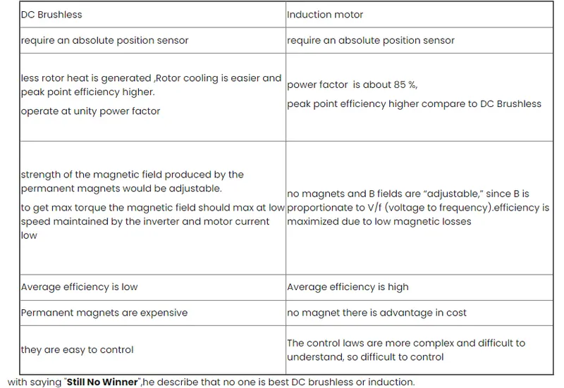
Inference: -
In the end, the author couldn't choose which drive is better than the other but makes it clear that DC Brushless motor drives will likely continue to dominate in the Hybrid and upcoming Plug-in hybrid markets and induction motor drives will likely maintain dominance for the high-performance pure electric.
Conclusion:
• We have discussed and studied the different types of power converter circuits employed in electric and hybrid electric vehicles.
• EV Steady-state speed of an EV Drivetrain was determined with the given input conditions.
• The Mathematical model for DC motor is developed.
• Lastly, we have studied a Blog on the Topic: -Induction Versus DC brushless motors by" Wally Rippel", "Nikola Tesla and explained in brief about the author's perspective.