Week -2
1. To Make a Simulink model of a doorbell using solenoid block.
2.create a Simulink model of thermistor to sense the temperature of a heater& turn on or turn off the fan.
AIM:
To Make a Simulink model of a doorbell using solenoid block.
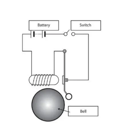
Solenoid: A Solenoid is a device comprised of a coil of wire, housing, and a moveable plunger (armature). When an electrical current is introduced, a magnetic field forms around the coil which draws the plunger in. More simply, a solenoid converts electrical energy into mechanical work.
The link shows the solenoid Simulink model
https://drive.google.com/file/d/1KP06x4gEmGi91ZkxhmqB5BCNEJVULby1/view?usp=sharing
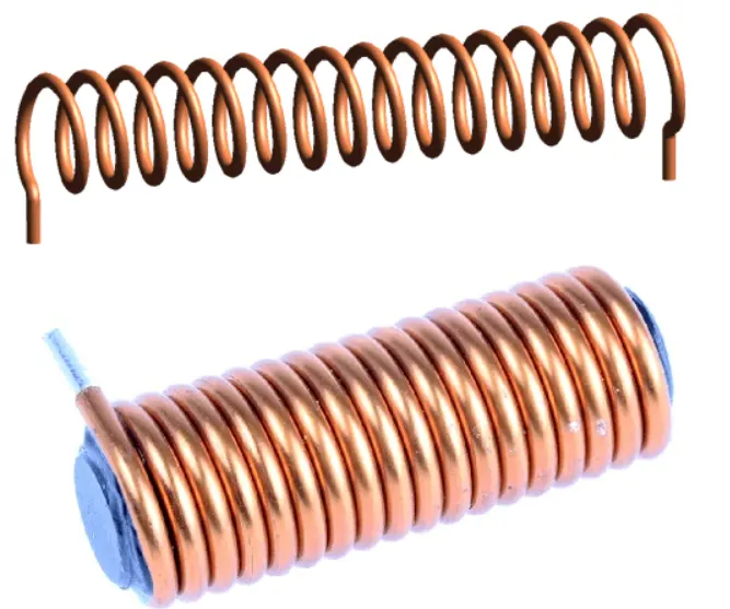
Solenoid Working Principle: https://youtu.be/BbmocfETTFo the link shows the working principle of solenoid.
The solenoid simply works on the principle of “electromagnetism”. When the current flow through the coil magnetic field is generated in it, if you place a metal core inside the coil the magnetic lines of flux is concentrated on the core which increases the induction of the coil as compared to the air core. This concept of electromagnetic induction.
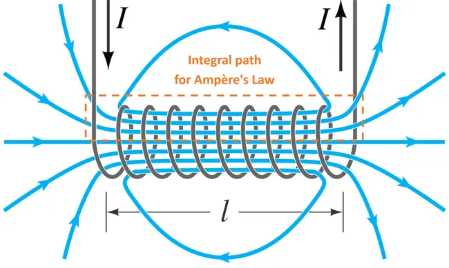
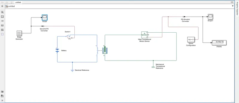
In Simulink, we use blocks to represent any system to get the desired output. In this project, we use some blocks to get our desired output.
1. pulse generator: The Pulse Generator block generates square wave pulses at regular intervals. The block waveform parameters, Amplitude, Pulse Width, Period, and Phase delay, determine the shape of the output waveform.
2. Simulink-PS Converter: It Converts the Simulink input signal into a physical signal.
3. Switch: Switch controlled by an external physical signal.
4. Battery: It gives the power to the close loop.
5. Electrical reference: It shows Connection to electrical ground. 6. Solenoid: Electrical characteristics and generated force of solenoid.
7. Ideal translational Motion Sensor: It is a motion sensor in mechanical translational systems.
8. PS-Simulink Converter: It Converts physical signal into Simulink output signal.
9. Mechanical Translational References: Reference connection for mechanical translational ports.
10. Scope: It displays signals generated during simulation.
BLOCK DIAGRAM OF SOLENOID:
BLOCK DIAGRAM PARAMETRS
BLOCK PARAMETERS SETTING
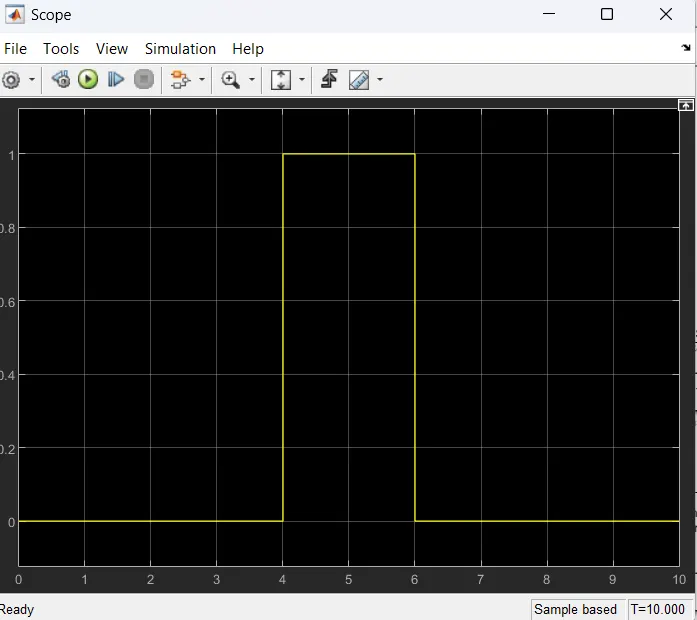
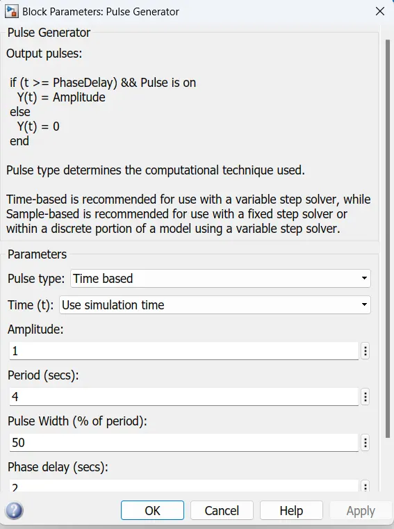
a. As per the settings in Pulse Generator- it is specified that Amplitude=1, Period(sec)=4, pulse width (% of period) =50, phase delay(sec)=2. Initially the pulse is at zero.
b. As the phase delay is set to 2sec, until! 2sec the pulse will be zero. After the 2sec the pulse will raise from 0 to 1 (as amplitude is set to 1) which means for next 2sec the pulse will be at amplitude-1.
c. And at 4th second, it will come back to zero. For the next 2sec it will at zero. And hence the cycle completes the period of 4sec.ln this way the cycle continues.
• Now, consider the solenoid block i.e. we have two ports 'Ft' & 'C'. Where R represents the plunger operation and C is the constant point
• The port-R in solenoid is connected to the port-R in the Ideal Translation Motion Sensor Block. This continuously senses the position of the plunger and give the output.
• In the Ideal Translation Motion Sensor there are 3 different connections in the output side i.e. connections "C', 'V', 'where 'V' & 'P' are the physical signal output ports for the velocity and the position.
• In this simulation, only the position of plunger is studied and recorded. Connection 'V' is left blank.
• The port-C of solenoid is connected to the connection-C of the output of Ideal Translational Motion Sensor Block. Also, both these connections are connected to the Mechanical Translation Reference.
• AS connection "P' indicates the position of plunger, it is connected to a PS-Simulink Converter. This converter, converts the input physical signal to a Simulink output signal.
• This PS-Simulink Converter is then connected to a Scope Block which generates a plot/graph showing the position of plunger from port-P of Ideal Translation Motion Sensor.
• Solver configuration block is connected to the model. Each physical network represented by a connected Sims cape block diagram require solver settings information for simulation.
• Finally, the simulation is set to Run by setting the stop time for lO sec.
OUTPUT RESULT:
output result of scope 1
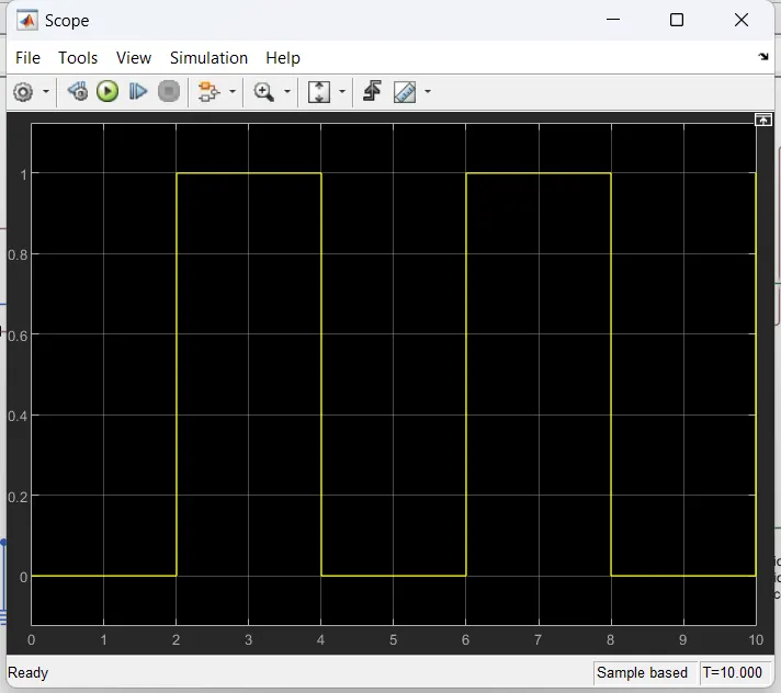
• After successfully running the simulation, the result can be visualized by using scope and also display block which shows the output value. • From the Simulink model, the Scope that is connected to the Pulse Generator displays the Amplitude vs Time plot i.e. it displays the pulse behaviour.
Based on the input data that is given in Pulse Generator Block, the above plot shows the pulse generation. This plot shows the situation where the switch is closed for 2 seconds and then released. As per the declared values, pulse generation has started after 2 seconds. At 2 seconds the amplitude maintained is 1 and then again for next 2 seconds the pulse is maintained zero. From the plot it is clear that, when amplitude is maintained at value 1 then the switch will be Turned Off and when it is zero the switch will Turn On.
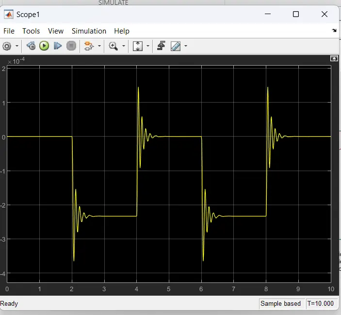
From the Simulink model, the 'Scope that is connected to the Ideal Translation Motion Sensor block displays the Position of plunger vs Time plot.
• The above plot shows the position of plunger at various time intervals.
• When we compare the Pulse Generator plot with the Position vs Time plot, it is observed that for the given time intervals the bell rings i.e. the bell start ringing at the interval of 2sec with the given phase delay of 2sec.
CONCLUSION
Hence from the above Simulink model of Doorbell using solenoid block is built. Using this model, a physical bell phenomenon is developed where the switch is closed for 2 seconds and then released. Also, the physical movement of the plunger is observed from the output plot.
AIM:
Create a Simulink Model of thermistor to sense the temperature of a heater & turn on or turn off the fan.
CONDITIONS:
Temperature source:20 °C from 0 to 10 secs,27°C from 10 to 30 secs,23°C from 30 to 50 seconds.
Fan Conditions=ON if the temperature above 25°C, OFF otherwise.
Blocks used in model
1) Repeating sequence stair
2) Thermistor: Temperature sensing element Negative temperature coefficient thermistor using B-parameter equate.
3) Resistor
4) Voltage sensor
5) controlled Temperature source: This block represents an ideal energy source in a thermal network that can maintain a controlled temperature difference regardless of the heat flow rate.
6) Battery
7) Lamp
8) Scope
9) Display
10) PS-Simulink Converter
11) Simulink-PS Converter
12) Solver Configuration
13) Switch
DESCRIPTION
Thermistor is a type of resistor whose resistance is strongly dependent on temperature; Thermistor is a sensor which is used to measure the temperature of the surrounding by comparing it with a known Temperature and resistance values
There are two types of thermistors they are Negative temperature co-efficient and positive temperature co efficient
A thermistor is a combination of both thermal and resistor.
The following the required Simulink block diagram for Turning ON or OFF the Fan, where a thermistor is used to sense the temperature of the heat source in-turn triggering to Turn ON or OFF the Fan. The details of the elements in the Simulink model are explained in the further steps.
SIMULINK MODEL:
https://drive.google.com/file/d/1zwIYzB4FKkMKU12Cwj_Ru_vrHj8FXbEF/view?usp=sharing link shows the Simulink model
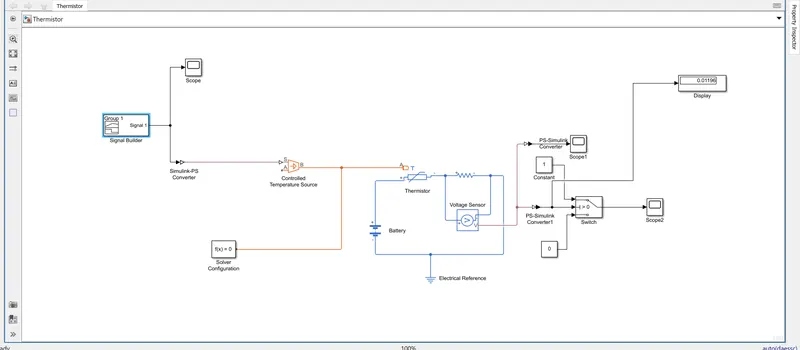
Using a Thermistor to sense the temperature of a heater & turn on or turn off the fan.
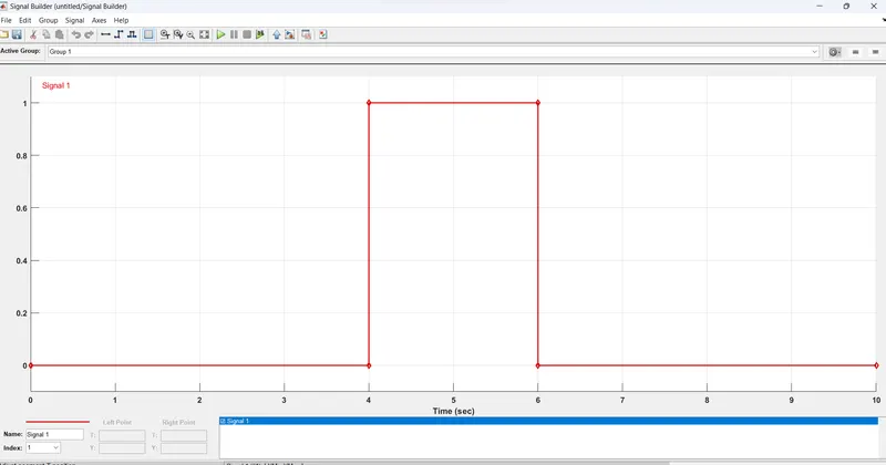
• The following is the Signal Builder Plot, where our required Temperature points are achieved. The Temperature source are set to the following conditions:
- o For Time Set " 0 to 10 " seconds, the Temperature is "293.15K".
- o For Time Set "10 to 30" seconds, the Temperature is "300.15K".
- o For Time Set "30 to 50" seconds, the Temperature is "296.15K".
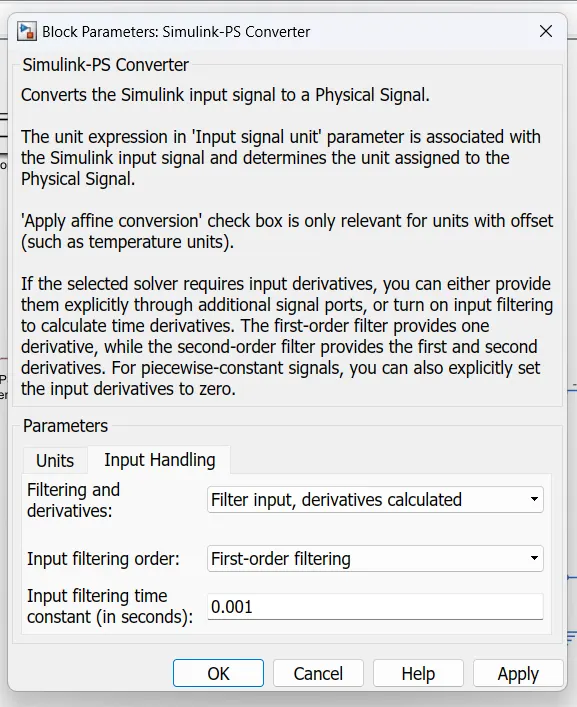
• The Simulink- PS converter converts the Simulink signals to a physical signal. As Signal Builder is a complex block unlike a constant block, we're required to let more derivatives to be achieved. For this, the Filtering and Derivatives parameter of the Simulink-PS block is set to "Filter input, derivatives calculated" option. Otherwise, there will be an error in the output.
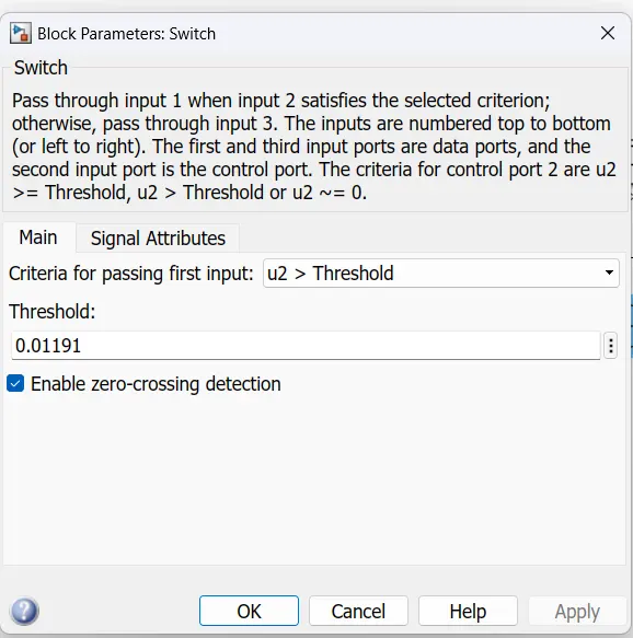
SWITCH BLOCK PARAMETERS:
OUTPUT:
The following is the output of the Simulink Model. We can observe that, the signal reaches the TURN ON mode from the Time Range 10 to 30. This output is similar to the input given in the Signal Builder. Thus, our simulation is correct and required output is achieved.