Project 1 (Mini Project on Vehicle Direction Detection
Aim Of the Project:-
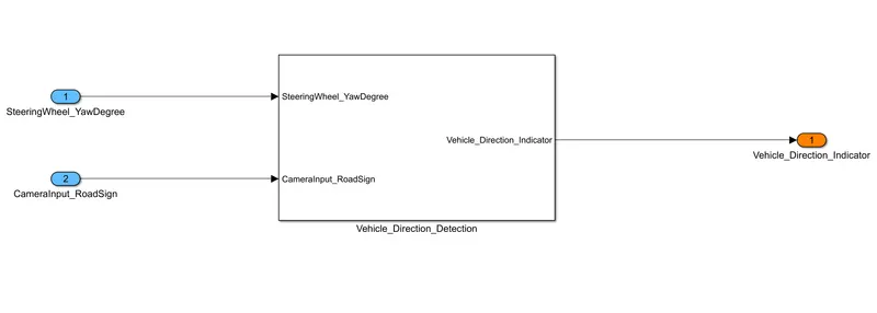
To identify the direction of the vehicle based on the camera input.
Objective Of The Project:-
- Development of MATLAB Simulink model as per requirement.
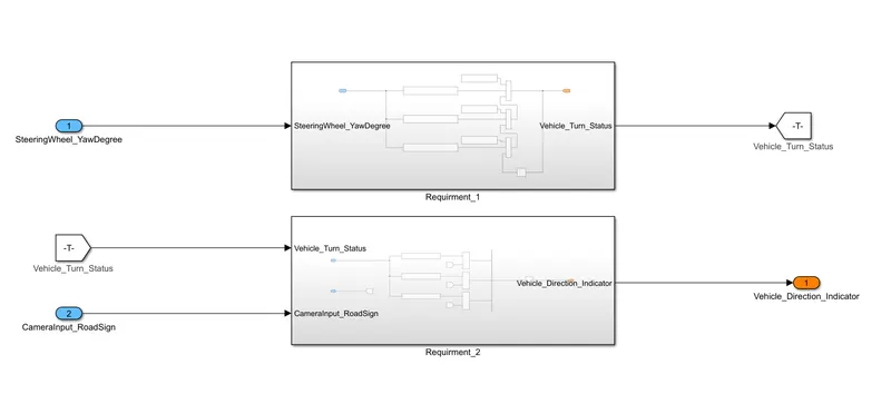
- Tag the requirements to the Simulink model; tagging requirements 1 & requirement 2 to their corresponding subsystems is acceptable.
- MBD-compliant changes, Data Dictionary creation & code generation is added advantage, and that is not the scope of this project.
- If choosing code generation, the Storage class for Input signals: ImportedExtern; the Storage class for Output signal: Is exported to File; the Storage class for local signals: is localizable; the Storage class for calibration signals: is Const.
- Choose sample time for all signals as 0.01s
Overview Of Using The System:-
Automatic vehicle direction detection using the vehicle camera system is an important feature of driver assistance systems. This system uses the camera installed in the vehicle to determine the direction in which the vehicle is traveling. The camera captures images of the road ahead and processes them to determine the direction of the vehicle.
- One of the main benefits of automatic vehicle direction detection is that it can assist drivers in navigating unfamiliar roads. The system can detect the vehicle's direction even if the driver is unfamiliar with the area. This can help drivers avoid getting lost or taking a wrong turn, which can be especially helpful in urban areas with complex road networks.
- Another benefit of this system is that it can assist drivers in navigating complex intersections. The system can detect the direction of the vehicle as it approaches an intersection and provide guidance to the driver on which lane to use or which direction to turn. This can help drivers navigate intersections safely and efficiently, reducing the risk of accidents. Automatic vehicle direction detection can also be used to improve the performance of other driver assistance systems, such as lane departure warning and forward collision warning. By accurately detecting the direction of the vehicle, these systems can provide more accurate and timely alerts to the driver, helping to prevent accidents and improve overall safety.
- There are a few different approaches to implementing automatic vehicle direction detection using the vehicle camera system. One common approach is to use computer vision algorithms to analyze the images captured by the camera and determine the direction of the vehicle based on visual cues such as lane markings and road signs. Another approach is to use GPS and map data to determine the direction of the vehicle based on its location and trajectory.
For this Project, there were several steps taken which are as follows
- Development of the Desired model
- Configuration Parameter Setting
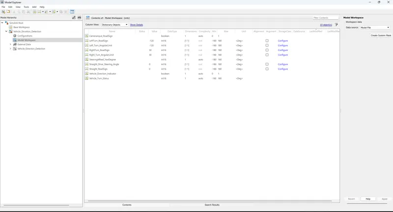
- Linking of the Simulink Data Dictionary
- Requirement Tagging
- Signal resolving and Signal Propagation
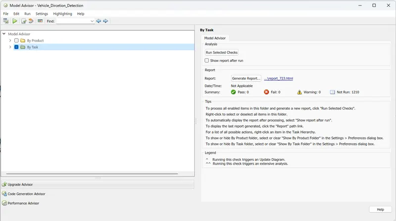
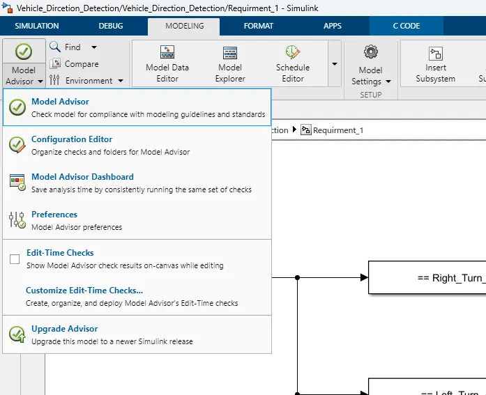
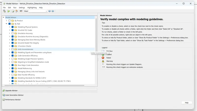
- Model Advisor Report Generation
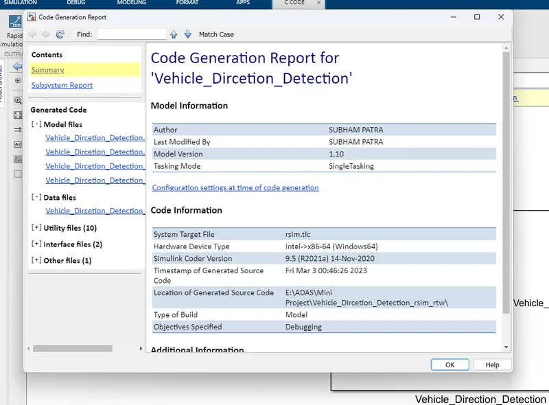
- C-code generation
Blocks Being Used:-
| Sl.No. | Name Of the Blocks | Quantity |
| 1. | Import | 7 |
| 2. | Outport | 4 |
| 3. | Compare To Constant | 6 |
| 4. | Constant | 3 |
| 5. | Goto | 2 |
| 6. | Switch | 3 |
| 7. | Unit Delay | 1 |
| 8. | Logical Operator (AND) | 3 |
| 9. | From | 4 |
| 10. | Signal Conversion | 1 |
| 11. | Mux | 1 |
Requirements And The required data:-
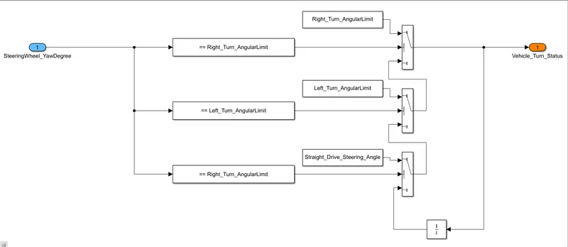
- Requirement - 1:
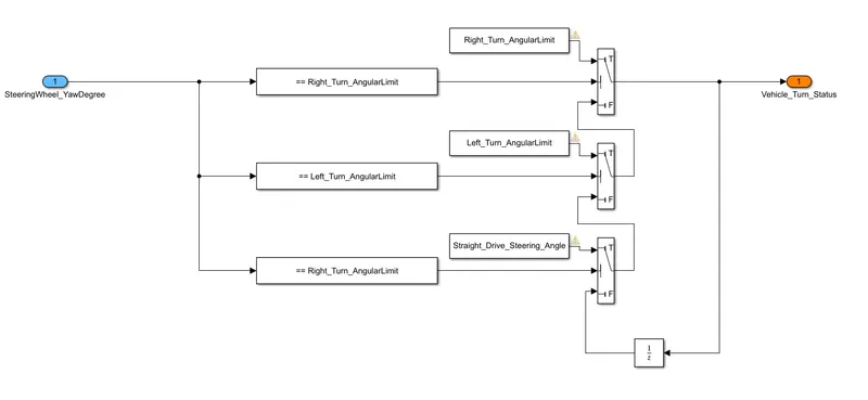
- Steering wheel input as yaw rate (Signal name: SteeringWheel_YawDegreeInput) is the input for this system.
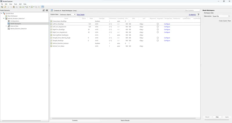
- This is compared against 3 angular values, one each for a left turn, right turn & straight drive (Calibration Values: Right_Turn_AngularLimit, Left_Turn_AngularLimit, Straight_Drive_Steering_Angle) to say which specific direction the steering wheel is turning towards.
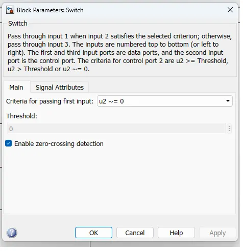
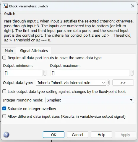
- Use switch blocks to compare & develop this requirement. Keep this requirement in a subsystem & the output of this requirement is a local signal (Signal Name: Vehicle_Turn_Status).
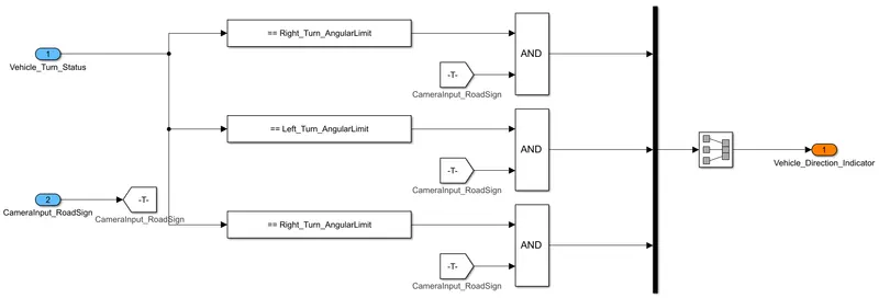
- Requirement – 2:
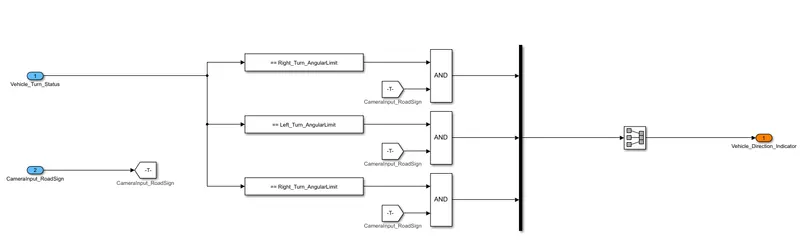
- Keep this requirement as a separate subsystem. Inputs to this requirement are a local signal from requirement 1 (Signal Name: Vehicle_Turn_Status) & an input signal from the camera (Signal Name: CameraInput_RoadSign), which confirms the occurrence of a road sign.
- Signal Vehicle_Turn_Status is compared against calibration values (Calibration Values: RightTurn_RoadSign, LeftTurn_RoadSign, Straight_RoadSign), if each of them is found equal, then each of the three corresponding outputs is compared against the camera input signal,
- Using a logical operator block, only one among them is finally given as the output signal (Signal Name: Vehicle_Direction_Indicator).
- Signals & Calibration Data List:
-
Signal / Calibration Name
Signal Type
Data Type
Dimension
Min
Max
Initial Value
Units
SteeringWheel_YawDegreeInput
Input
Int16
1
-180
180
-
Deg
CameraInput_RoadSign
Input
Boolean
1
0
1
-
-
Vehicle_Turn_Status
Local
Int16
1
-180
180
-
Deg
Right_Turn_AngularLimit
Calibration
Int16
[1 1]
-180
180
30
Deg
Left_Turn_AngularLimit
Calibration
Int16
[1 1]
-180
180
-120
Deg
Straight_Drive_Steering_Angle
Calibration
Int16
[1 1]
-180
180
0
Deg
RightTurn_RoadSign
Calibration
Int16
[1 1]
-180
180
30
LeftTurn_RoadSign
Calibration
Int16
[1 1]
-180
180
-120
Straight_RoadSign
Calibration
Int16
[1 1]
-180
180
0
Vehicle_Direction_Indicator
Output
Boolean
1
0
1
-
-
-
Steps For Modeling:-
|
||
|
||
|
||
|
||
Observation:-
 |
 |
 |
 |
 |
 |
 |
 |
 |
|
|
Conclusion:-.
We have perform the simple project for theAutomatic direction detection for an Vehicle, all the files including the code files are been presented in the file.