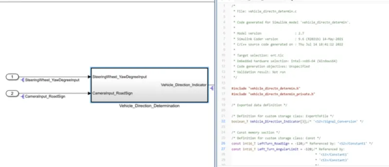
Project 1 (Mini Project on Vehicle Direction Detection
AIM:
- The main objective of this project is to create a MBD based MATLAB Simulink model for vehicle direction detection as per the requirement specified.
- Requirement tagging for Requirement 1 & Requirement 2 subsystems in the Simulink model with the respective selection in word document.
- Creation of Simulink Data Dictionary and linking it to the developed model
OBJICTIVE:
- To create a simulink model as per requirement.
- Create the subsystem for tagging requirement 1 & requirement 2
- To create the sldd based on the given requirement
SIMULATION MODEL:
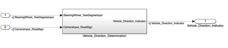
The main system 'Vehicle_Direction' along with inputs 'SteeringWheel_YawDegreeInput' , 'CameraInput_RoadSign' and output signal ' Vehicle_Direction_Indicator' is shown below,
SUBSYSTEM:(Vehicel_Direction)
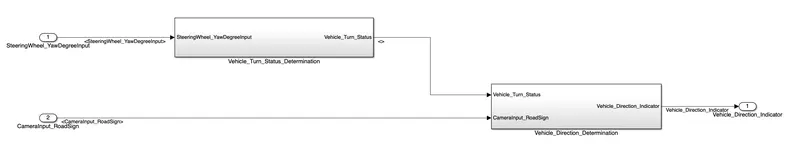
The main subsystem 'Vehicle_Direction' is further divided into two more subsytems which are 'Requirement1' and 'Requirement2' as shown below,
Requirement-1(Explanation):
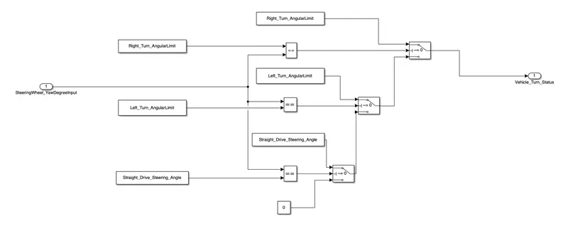
* In the 'Requirement1' subsystem, the steering wheel yaw degree (Signal name: SteeringWheel_YawDegreeInput) is fed as input to the subsystem and this value is compared against 3 angular values, one each for left turn, right turn & straight drive (Calibration Values: Right_Turn_AngularLimit, Left_Turn_AngularLimit, Straight_Drive_Steering_Angle) to say which specific direction the steering wheel is turning towards.
* The input signal 'SteeringWheel_YawDegreeInput' is compared against three angular values using the relational operator '==', one each for left turn, right turn & straight drive (Calibration Values: Right_Turn_AngularLimit, Left_Turn_AngularLimit, Straight_Drive_Steering_Angle) to say which specific direction the steering wheel is turning towards. In this case, the output of the relational operator '==' is equal to 1 only when the 'SteeringWheel_YawDegreeInput' matches the calibraton value angular limit specified in Right_Turn_AngularLimit, Left_Turn_AngularLimit, or Straight_Drive_Steering_Angle.
* Three switch blocks are used to implement an if-else logic. The output from each relational operator is given as a condition input (input2) to each Switch block. The switch will pass input1 (calibration value) when the condition (input2~=0) condition is satisfied, else input3 (output from the next switch block) is passed as output.
* The signal 'Vehicle_Turn_Status' obtained at the output of the first switch will be a calibration angular value (Right_Turn_AngularLimit OR Left_Turn_AngularLimit, OR Straight_Drive_Steering_Angle).
* If none of the conditions get satisfied, zero is passed as the output from the last switch. The signal 'Vehicle_Turn_Status' is fed to the outport of subsystem 'Requirement1'
Requirement-2(Explanation):
* In Requirement-2 , the local signal 'Vehicle_Turn_Status' fed from 'Requirement1' subsystem is taken as input and is compared against calibration values (RightTurn_RoadSign, LeftTurn_RoadSign, Straight_RoadSign) using the relational operator '=='.
* The boolean value obatined at the output of the realtional operator is compared against a boolean input signal from camera (Signal Name: CameraInput_RoadSign), which confirms the occurrence of a road sign using 'AND' operotor.
* The boolean output signal obtained from each of the three 'AND' blocks are fed to the outport 'Vehicle_Direction_Indicator' to indicate the vehicle direction.
* The output 'Vehicle_Direction_Indicator' will be a three dimension signal having three boolean elements, with the first element to indicate 'Right Turn', second element to indicate 'Left Turn' and third element to indicate 'Straight Drive'
Data value:
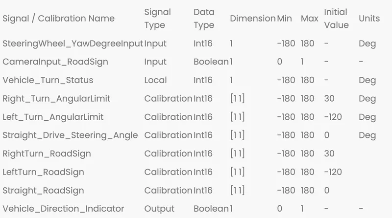
Simulink data dictinoary file sldd(Creation):
A Simulink Data Dictionary (SLDD) file is created that contains input, output signals and calibration parameters used in the model. SLDD file is created by clicking on Modeling, then ‘Model Properties’, then ‘External Data’ and specifying a file name for the Data Dictionary.
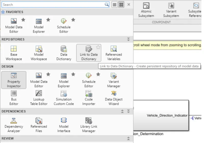
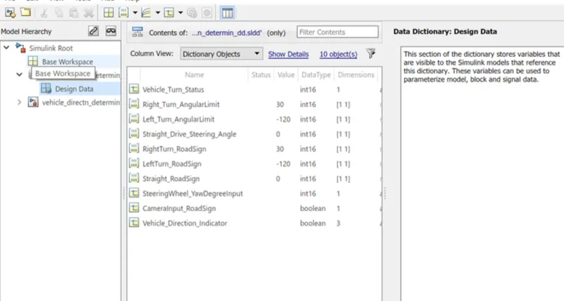
Requirement Tagging of Simulink Model:
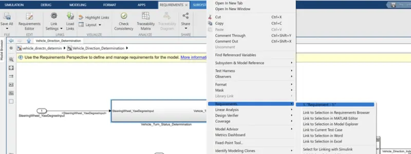
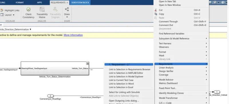
* The requirements ‘Requirement-1’ and ‘Requirement-2’ as provided in the Requirements Word document are tagged to their respective subsystem in the Simulink Model.
* The steps involved in tagging a requirement in the Simulink model is to first highlight the requirement statement in the Word document, then right click on the subsystem in the model that has to be tagged, then select ‘Requirements’ and then ‘Link to Selection in Word’
Requirement-1
Requirement-2
C code :
#include "vehicle_directn_determin.h"
#include "vehicle_directn_determin_private.h"

/* Exported data definition */

/* Definition for custom storage class: ExportToFile */
boolean_T Vehicle_Direction_Indicator[3];/* '<S2>/Signal_Conversion' */

/* Const memory section */
/* Definition for custom storage class: Const */
const int16_T LeftTurn_RoadSign = -120;/* Referenced by: '<S2>/Constant1' */
const int16_T Left_Turn_AngularLimit = -120;/* Referenced by:
                                             * '<S3>/Constant1'
                                             * '<S3>/Constant3'
                                             */
const int16_T RightTurn_RoadSign = 30; /* Referenced by: '<S2>/Constant' */
const int16_T Right_Turn_AngularLimit = 30;/* Referenced by:
                                            * '<S3>/Right_Turn_AngularLimit'
                                            * '<S3>/Right_Turn_AngularLimit1'
                                            */
const int16_T Straight_Drive_Steering_Angle = 0;/* Referenced by:
                                                 * '<S3>/Constant2'
                                                 * '<S3>/Constant4'
                                                 */
const int16_T Straight_RoadSign = 0;   /* Referenced by: '<S2>/Constant2' */

/* Real-time model */
static RT_MODEL_vehicle_directn_dete_T vehicle_directn_determin_M_;
RT_MODEL_vehicle_directn_dete_T *const vehicle_directn_determin_M =
  &vehicle_directn_determin_M_;

/* Model step function */
void vehicle_directn_determin_step(void)
{
  int32_T rtb_Switch;

  /* Outputs for Atomic SubSystem: '<Root>/Vehicle_Direction_Determination' */
  /* Switch: '<S3>/Switch' incorporates:
   *  Constant: '<S3>/Constant1'
   *  Constant: '<S3>/Constant2'
   *  Constant: '<S3>/Right_Turn_AngularLimit'
   *  Constant: '<S3>/Right_Turn_AngularLimit1'
   *  Inport: '<Root>/Input'
   *  RelationalOperator: '<S3>/Equal'
   *  RelationalOperator: '<S3>/Equal1'
   *  RelationalOperator: '<S3>/Equal2'
   *  Switch: '<S3>/Switch1'
   *  Switch: '<S3>/Switch2'
   */
  if (Right_Turn_AngularLimit == SteeringWheel_YawDegreeInput) {
    rtb_Switch = Right_Turn_AngularLimit;
  } else if (SteeringWheel_YawDegreeInput == Left_Turn_AngularLimit) {
    /* Switch: '<S3>/Switch1' incorporates:
     *  Constant: '<S3>/Constant3'
     */
    rtb_Switch = Left_Turn_AngularLimit;
  } else if (SteeringWheel_YawDegreeInput == Straight_Drive_Steering_Angle) {
    /* Switch: '<S3>/Switch2' incorporates:
     *  Constant: '<S3>/Constant4'
     *  Switch: '<S3>/Switch1'
     */
    rtb_Switch = Straight_Drive_Steering_Angle;
  } else {
    /* Switch: '<S3>/Switch1' incorporates:
     *  Constant: '<S3>/Constant'
     *  Switch: '<S3>/Switch2'
     */
    rtb_Switch = 0;
  }

  /* End of Switch: '<S3>/Switch' */

  /* SignalConversion: '<S2>/Signal_Conversion' incorporates:
   *  Constant: '<S2>/Constant'
   *  Constant: '<S2>/Constant1'
   *  Constant: '<S2>/Constant2'
   *  Inport: '<Root>/Input1'
   *  Logic: '<S2>/AND'
   *  Logic: '<S2>/AND1'
   *  Logic: '<S2>/AND2'
   *  RelationalOperator: '<S2>/Equal'
   *  RelationalOperator: '<S2>/Equal1'
   *  RelationalOperator: '<S2>/Equal2'
   */
  Vehicle_Direction_Indicator[0] = ((rtb_Switch == RightTurn_RoadSign) &&
    CameraInput_RoadSign);
  Vehicle_Direction_Indicator[1] = ((rtb_Switch == LeftTurn_RoadSign) &&
    CameraInput_RoadSign);
  Vehicle_Direction_Indicator[2] = ((rtb_Switch == Straight_RoadSign) &&
    CameraInput_RoadSign);

  /* End of Outputs for SubSystem: '<Root>/Vehicle_Direction_Determination' */
}

/* Model initialize function */
void vehicle_directn_determin_initialize(void)
{
  /* (no initialization code required) */
}

/* Model terminate function */
void vehicle_directn_determin_terminate(void)
{
  /* (no terminate code required) */
}

/*
 * File trailer for generated code.
 *
 * [EOF]
 */