Project 1 (Mini Project on Vehicle Direction Detection
Aim: Identify the direction of the vehicle using Steering wheel angular data and camera input that reads the road signs and generate the turn indication for the vehicle.
Description and Simulink model:
Step 1:
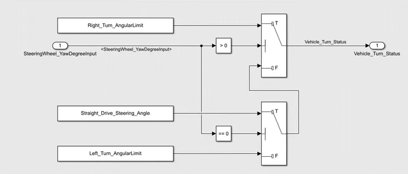
Requirement 1 will be considered as Subsystem 1 that will be checking the Steering wheel status with the calibration values.
As given in the statement for requirement 1, the Steering Wheel input will be monitored as per its degree of movement. When the Steering Wheel input meets the required Angular limit for right or left, the switch block will give the required output as Vehicle Turn Status.
Step 2:
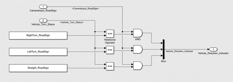
Requirement 2 will be considered as Subsystem 2 that will be checking the Camera input and Steering status with the Road Sign calibration values to provide the vehicle turning indicator.
As given in the statement for requirement 2, the output obtained from the requirement 1 (Vehicle Turn Status) is compared with the Road Signs calibration values with the help of relational operator. The output of this relational operator is then logically compared with Camera Input using logical operator AND. The output obtained from these logical operators are then given to Mux, which will select the output with TRUE value for the required conditions.
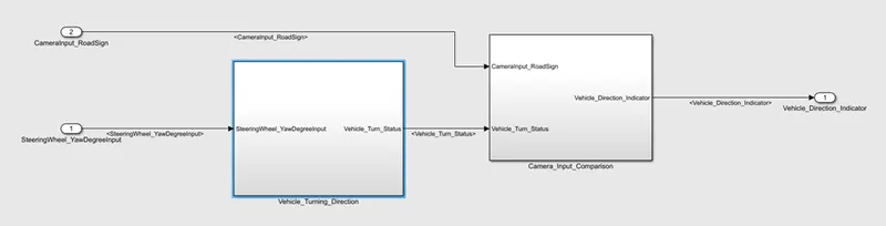
Step 3: Getting inputs for requirement 1 & 2-
Connecting both the subsystems 1&2 as per the required conditions, inputs and outputs.
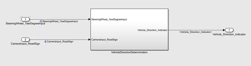
Step 4: Create a complete final subsystem with “Vehicle Direction Determination” name that includes subsystem logics from requirement 1&2.
Step 5:
Creation of SLDD as per the data mentioned in the problem statement.
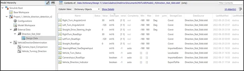
Step 6: Configuration parametr settings
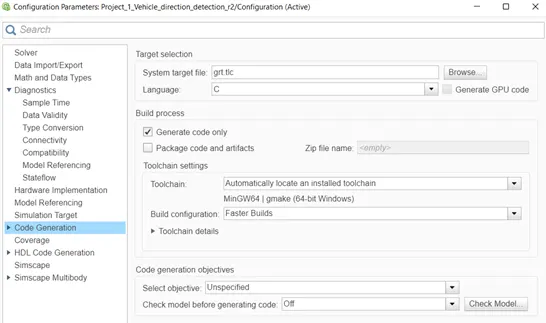
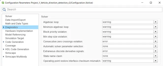
In order to generate a report of the model, some configuration parameters settings are required that can be done in Modeling Tab > Model settings > Model properties.
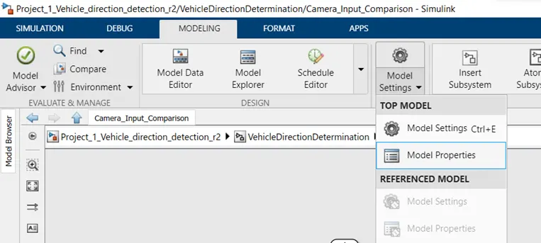
Make the required configuration settings as per the project’s demand. In this project, some parameters have been updated as follows:
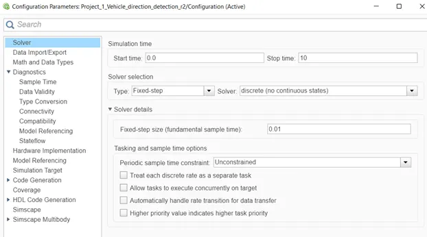
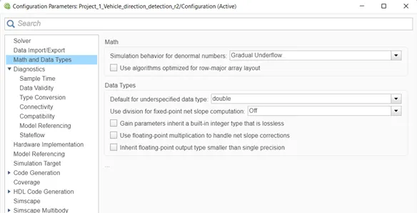
Step 7: Run Model Advisory test
After making necessary changes in the configuration parameters, a model advisory report needs to be generated with all the possible or selected configurations.
In the APPS tab > Model verification, validation and test > click on “Model Advisor”
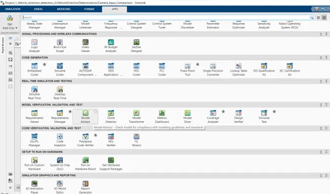
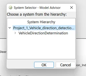
After clicking on the Model Advisor, a pop-up window appears which asks user to select the system for which the action needs to be performed.
Following window pops-up which shows the list of tasks that will be verified by Model Advisor while performing the test.
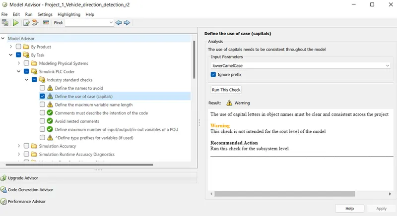
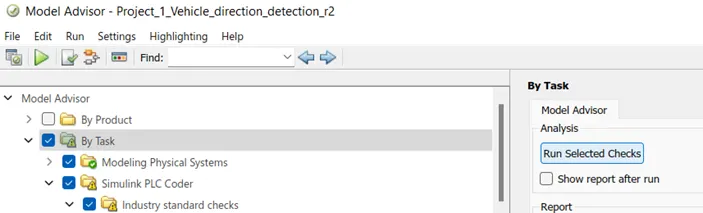
Check on the TASK section to perform full test of the system and click on “Run Selected Checks”.
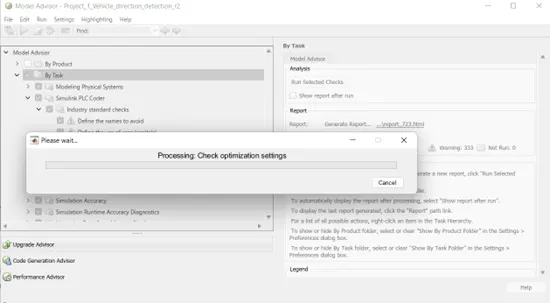
The Simulink model will take some time to process the test and prepare test reports.
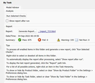
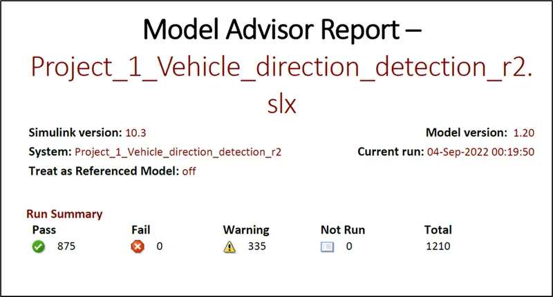
After the completion of model advisor check, it will give the summary of the Pass, fail and warning data. If there are any errors or warnings, try to minimize and correct them.
Step 8: Generate Model Advisory report
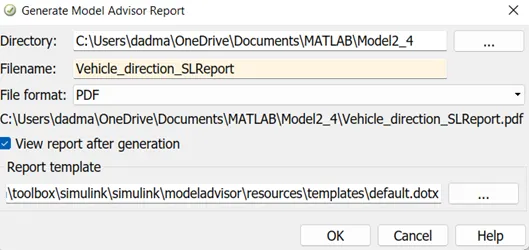
Once the errors and warnings are resolved, click on Generate Report. A pop-up will appear asking for the file name, its location and file format. Enter the data as required and click on OK.
Since, this model report format is selected as PDF. Hence, the report is generated in PDF format.
Step 9: Generate C-code
After resolving the errors and warnings, next step is to Generate C-code.
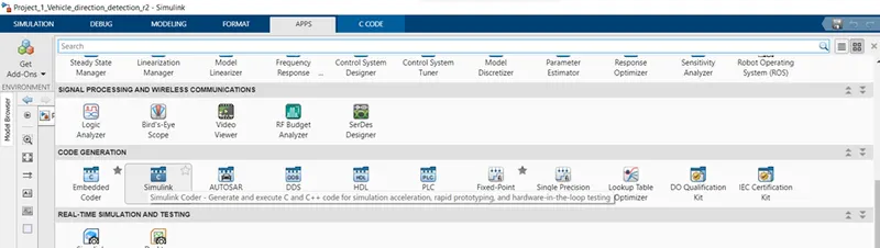
Go to “APPS” >> in that, under code generation section click on “Simulink Coder”
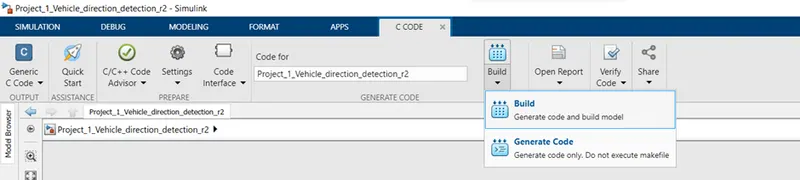
A new “C code” tab appears, in that click on “Build” and “Generate Code”.
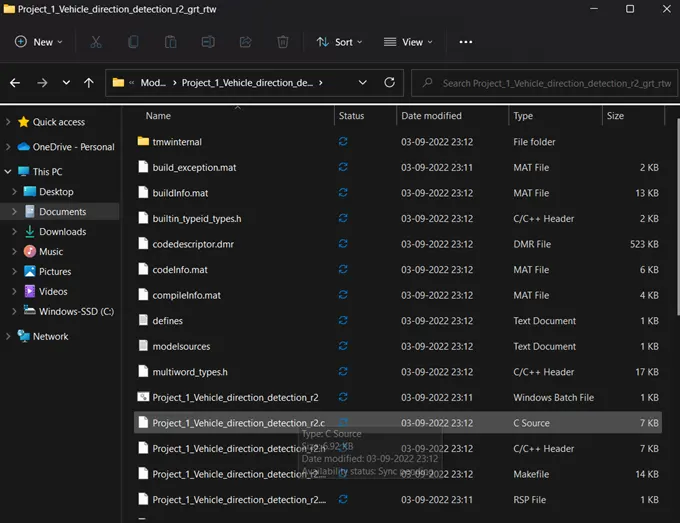
The code will be generated and stored in the Simulink project folder as shown below:
Results: 1. In this way a subsystem has been which will compare the steering wheel input and camera input to provide the indicator for vehicle turning.
2.After generating the subsystem, it is necessary to resolve the signals at input and output level. For this, SLDD is created with all the necessary Simulink signals and parameters data.
3.Run the Model Advisor and generate the report to check the model reliability and for any errors that might have been missed while designing the system.
4. Generate the C-code which can be later used in hardware model to implement the vehicle direction determination module as a part of it.