Project 1 (Mini Project on Vehicle Direction Detection
AIM: To Model the Vehicle Direction detection logic based on the camera input and its comparison with the steering wheel input.
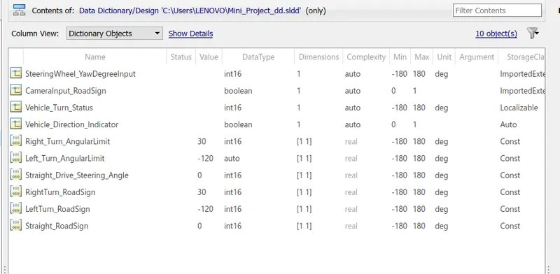
The signals and calibration values in the in the data list are used to create the data dictionary for the required model as shown below:
REQUIREMENT 1 SUBSYSTEM:
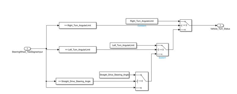
The model for the requirement 1 is as shown below, switch blocks have been used as mentioned in the requirement.
Explanation
- The steering wheel input is compared with the right turn angle, left angle and straight angle limits using compare to constant blocks and the output is used to enable the switch block connected to it.
- The TRUE part of the switch block passes the same turn limit(either right, left or straight) and the FALSE part passes the input of the next comparison.
- If the input is not equal to any of the given limits, then it is passed as it is in the output "Vehicle_Turn_Status".
The above logic has been converted to the subsystem named "Requirement1" as shown below: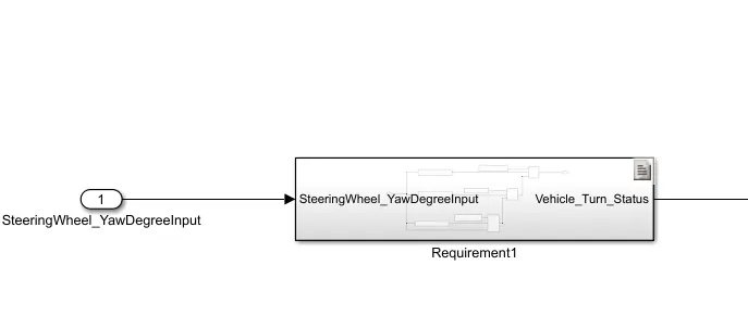
The output of this subsystem is used as input to the second subsystem named as "Requirement2", as shown below:
REQUIREMENT 2 SUBSYSTEM:
The logic required in the requirement 2 is as shown in the image below: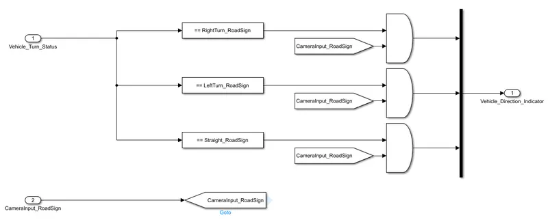
EXPLANATION:
- The output from the requirement 1 is used as an input to the requirement 2, and the signal is compared with the right, left and straight road signs.
- If the outputs of all the three comparisons are high, then they are individually compared with the camera input signal.
- The second comparison has been implemented using the AND logic gate blocks which ensure that the "Vehicle Direction indicator" is displaying the value as per the obtained camera input.
- The MUX ensures that the only one signal is displayed by the indicator at a time.
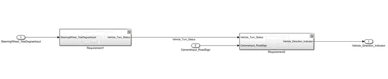
THE OVERALL SIMULINK MODEL IS AS SHOWN BELOW:
TESTING:
1. REQUIREMENT 1:
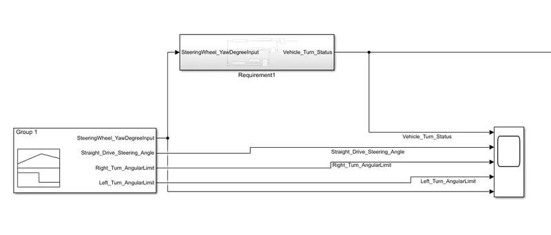
Both the reuirements are tested individually and also combined further, the test setup for the first one is as shown below:
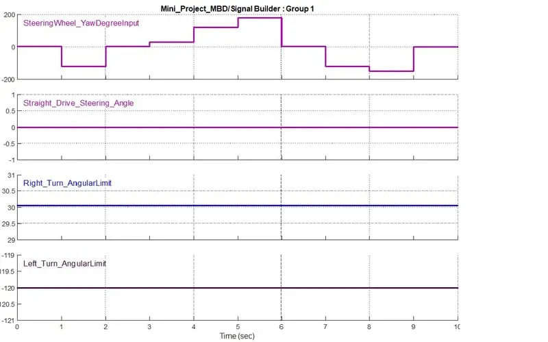
TEST CASES FOR THE FIRST REQ:
The results after simulation of the subsystem 1 is as shown below:
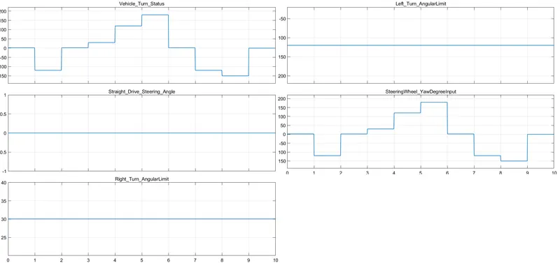
It can be seen from the above plot that the output "Vehicle_Turn_Status" traces the values of the Right,left and straight angle whenever the input signal has the same value.
Also, when the input signal is not equal to any of them, the output simply traces it.
2. REQUIREMENT 2:
The test setup for the second requirment is as shown below, the output of the subsystem is seperated using a demux for the ease of test verification:
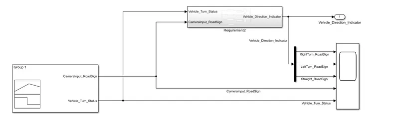
The test cases for the requirement has signals of both the inputs and the input "Vehicle_Turn_Status" used here has the same waveform as obtained fom the output of the previous requirement.
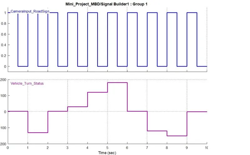
It can be seen that the "CameraInput_RoadSign" is a boolean variable and takes periodic low and high values.
RESULTS:
THE RESULTS OBTAINED AFTER SIMUALTION ARE AS SHOWN BELOW:
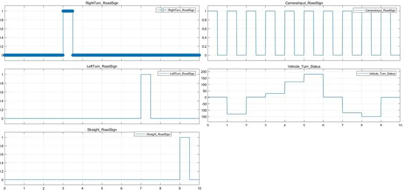
EXPLANATION:
- The first output of the demux becomes high in the duration "t=3 sec" to "t=3.5 sec" since the "CameraInput_RoadSign" is high and the ''Vehicle_Turn_Status" is equal to the "Right" road sign value.
- The second output of the demux becomes high in the duration "t=7 sec" to "t=7.5 sec" since the "CameraInput_RoadSign" is high and the ''Vehicle_Turn_Status" is equal to the "Left" road sign value.
- Similarly, the third output of the demux becomes high in the duration "t=9 sec" to "t=9.5 sec" since the "CameraInput_RoadSign" is high and the ''Vehicle_Turn_Status" is equal to the "Straight" road sign value.
NOTE: THE SIMULINK MODEL AND THE DATA DICTIONARY ARE ATTACHED IN THE NAMES "Mini_Project_MBD" and "Mini_Project_dd" respectively.