Project 1 (Mini Project on Vehicle Direction Detection
Project 1 (Mini Project on Vehicle Direction Detection
Aim:
-
Mini Project - Vehicle Direction Determination
General Overview:
Identifying the direction of the vehicle is one of the important & diverse features in Autonomous driving & Advanced Driver Assistance Features. This particular sub-feature of identifying the direction of the vehicle is basically identifying the direction the vehicle is taking based on the camera input.
The camera reads the road signs & stores them into its memory with unique values for a left turn, right turn & straight drive. Depending on the direction it is taking, the final indication is given to the driver – as an indication if he is driving in the recommended direction or not.
Vehicle Direction Determination can also be coupled alongside features like GPS systems to identify whether the vehicle is reaching its destination in an optimized manner. This sub-feature can also be used along with Lane Detection, Highway Warning, Ramp Entry / Exit in Wrong Way Detection, etc.
The objective of the Mini Project:
- Development of MATLAB Simulink model as per requirement.
- Tag the requirements to the Simulink model; tagging requirement 1 & requirement 2 to their corresponding subsystems is fine.
- MBD compliant changes, Data Dictionary creation & code generation is added advantage, and that is not the scope of this project.
- If choosing code generation, Storage class for Input signals: ImportedExtern; Storage class for Output signal: Export to File; Storage class for local signals: localizable; Storage class for calibration signals: Const.
- Choose sample time for all signals as 0.01s
Requirement - 1:
- Steering wheel input as yaw rate (Signal name: SteeringWheel_YawDegreeInput) is the input for this system.
- This is compared against 3 angular values, one each for a left turn, right turn & straight drive (Calibration Values: Right_Turn_AngularLimit, Left_Turn_AngularLimit, Straight_Drive_Steering_Angle) to say which specific direction the steering wheel is turning towards.
- Use switch blocks to compare & develop this requirement. Keep this requirement in a subsystem & the output of this requirement is a local signal (Signal Name: Vehicle_Turn_Status).
Requirement – 2:
- Keep this requirement as a separate subsystem. Inputs to this requirement are a local signal from requirement 1 (Signal Name: Vehicle_Turn_Status) & an input signal from the camera (Signal Name: CameraInput_RoadSign), which confirms the occurrence of a road sign.
- Signal Vehicle_Turn_Status is compared against calibration values (Calibration Values: RightTurn_RoadSign, LeftTurn_RoadSign, Straight_RoadSign), if each of them is found equal, then each of the three corresponding outputs is compared against the camera input signal,
- Using a logical operator block, only one among them is finally given as the output signal (Signal Name: Vehicle_Direction_Indicator).
Signals & Calibration Data List:
Signal / Calibration Name
Signal Type
Data Type
Dimension
Min
Max
Initial Value
Units
SteeringWheel_YawDegreeInput
Input
Int16
1
-180
180
-
Deg
CameraInput_RoadSign
Input
Boolean
1
0
1
-
-
Vehicle_Turn_Status
Local
Int16
1
-180
180
-
Deg
Right_Turn_AngularLimit
Calibration
Int16
[1 1]
-180
180
30
Deg
Left_Turn_AngularLimit
Calibration
Int16
[1 1]
-180
180
-120
Deg
Straight_Drive_Steering_Angle
Calibration
Int16
[1 1]
-180
180
0
Deg
RightTurn_RoadSign
Calibration
Int16
[1 1]
-180
180
30
LeftTurn_RoadSign
Calibration
Int16
[1 1]
-180
180
-120
Straight_RoadSign
Calibration
Int16
[1 1]
-180
180
0
Vehicle_Direction_Indicator
Output
Boolean
1
0
1
-
-
Model Used Blocks:
- Input Blocks: provide the input signals
- Constant Blocks: Define the calibration values
- Logical operator Blocks: OR blocks are used to compare the road signs with camera input and to get the boolean output.
- Switch Blocks: compare the input with the calibration values.
- Mux Block: combine the signals
- Output Blocks: send the output signals
- Display Block: display the results
Simulink Model:
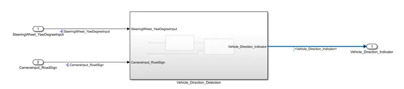
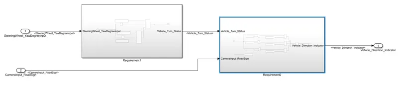
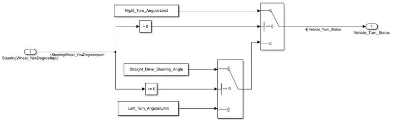
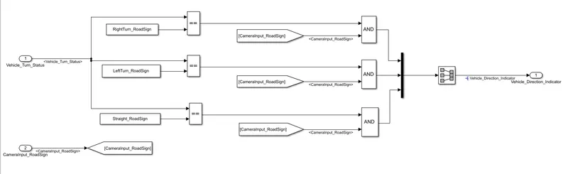
SLDD File:
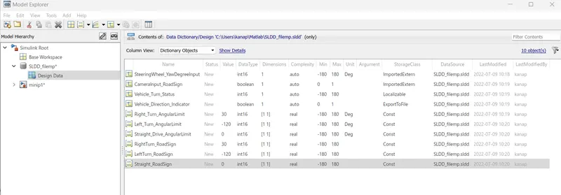
The SLDD file is created to store the calibration values and input and output signals to the Simulink model.
Explanation:
The logic in the Requirement:1
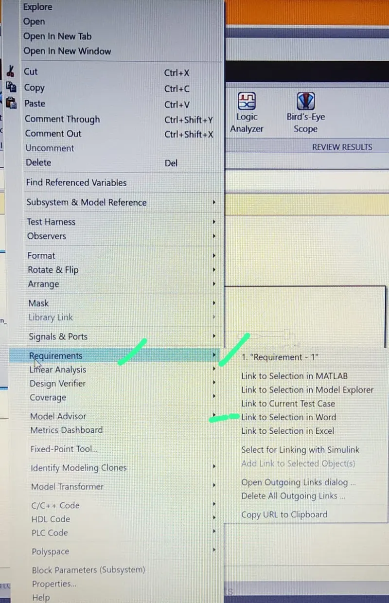
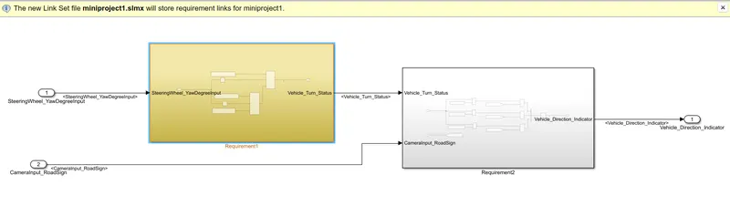
If the input is >=30 (because the initial value is 30) the vehicle will take the Right turn, else If the input is not equal to zero (~=0) the vehicle left_turn, else stright_drive (if the input is equal to zero).
The input yaw rate is given to the middle part of the switch, and the threshold value is 30. If the input is greater than the threshold value then the switch will take the True condition (Right_Turn_AngularLimit) or else the false condition. In the second switch, the threshold value is zero, if the threshold value is not equal to zero then the switch will take the true condition (Left_Turn_AngularLimit) else takes the false condition (Sitight_Drive steering_Angle). This output from the second switch is given as a false condition to the first switch. And the output for the Requirement_1 is "Vehicle_Turn_Status".
The logic in the Requirement:2
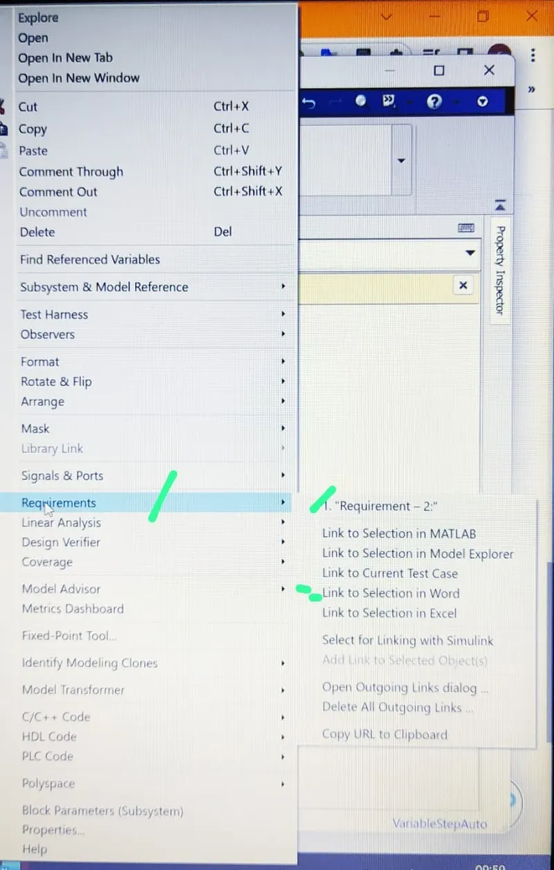
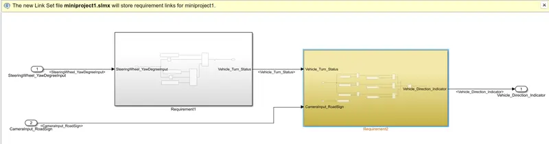
To compare the "Vehicle_Turn_Status" (Output of Requirement_1) with "RoadSign" and an input signal from the camera to get the Vehicle Direction indicator.
After comparison with "Vehicle_Turn_Status" if each of them is found equal, then each of the three corresponding outputs is compared against the camera input signal, by using the 'logical OR' Blocks will get the true case and take only one among them as output, the 'Mux' block is used. And the final output from the Vehicle_Detection Model will indicate the vehicle_Direction indication. Next by adding the SLDD_file to the model and by loading the calibration values and input/output values are defined.
Running the simulation will get the vehicle direction.
Code Generation:
Model Advisor
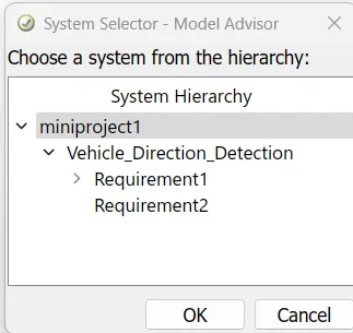
open model advisor and select the system Hierarchy is shown below.
click by task option

And check the Modeling standards for MAB option.
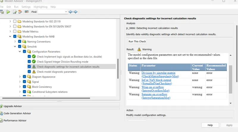
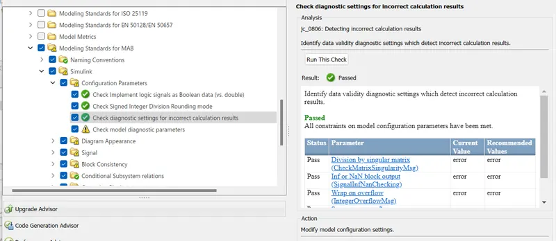
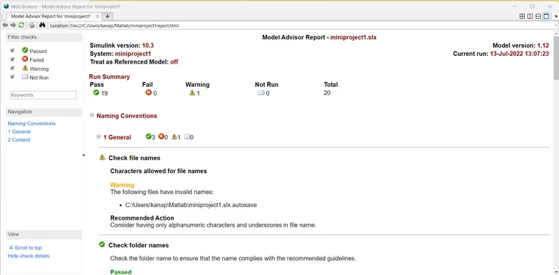
Model Advisor Report - miniproject1.slx
Simulink version: 10.3	Model version: 1.12
System: miniproject1	Current run: 13-Jul-2022 13:07:23
Treat as Referenced Model: off

Run Summary
Pass	Fail	Warning	Not Run	Total
   19	   0	   1	   0	20


 Naming Conventions


     1 General  3  0  1  0
  Check file names
Characters allowed for file names

Warning
The following files have invalid names:

C:\Users\kanap\Matlab\miniproject1.slx.autosave
Recommended Action
Consider having only alphanumeric characters and underscores in file name.
  Check folder names
Check the folder name to ensure that the name complies with the recommended guidelines.

Passed
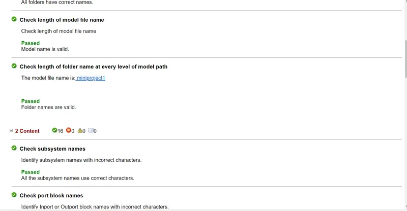
All folders have correct names.

  Check length of model file name
Check length of model file name

Passed
Model name is valid.

  Check length of folder name at every level of model path
The model file name is: miniproject1


Passed
Folder names are valid.


     2 Content  16  0  0  0
  Check subsystem names
Identify subsystem names with incorrect characters.

Passed
All the subsystem names use correct characters.

  Check port block names
Identify Inport or Outport block names with incorrect characters.

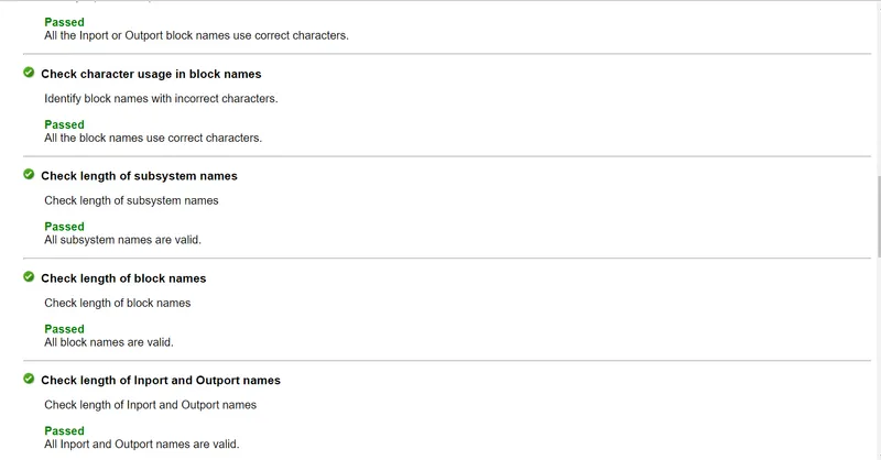
Passed
All the Inport or Outport block names use correct characters.

  Check character usage in block names
Identify block names with incorrect characters.

Passed
All the block names use correct characters.

  Check length of subsystem names
Check length of subsystem names

Passed
All subsystem names are valid.

  Check length of block names
Check length of block names

Passed
All block names are valid.

  Check length of Inport and Outport names
Check length of Inport and Outport names

Passed
All Inport and Outport names are valid.

  Check character usage in signal names and bus names
Identify signal and bus names with invalid characters.

Passed
No invalid characters are used in signal and bus names.

  Check character usage in parameter names
Identify parameter names with invalid characters.

Passed
No invalid characters are used in parameter names.

  Check length of signal and bus names
Check length of signal and bus names

Passed
All signal and bus names are valid.

  Check length of parameter names
Check length of parameter names

Passed
All parameter names are valid.

  Check character usage in Stateflow data names
Identify Stateflow data names with invalid characters.

Passed
No invalid characters are used in Stateflow data names.

  Check length of Stateflow data name
Check if the length of Stateflow data names are within limit.

Passed
All Stateflow data names are valid.

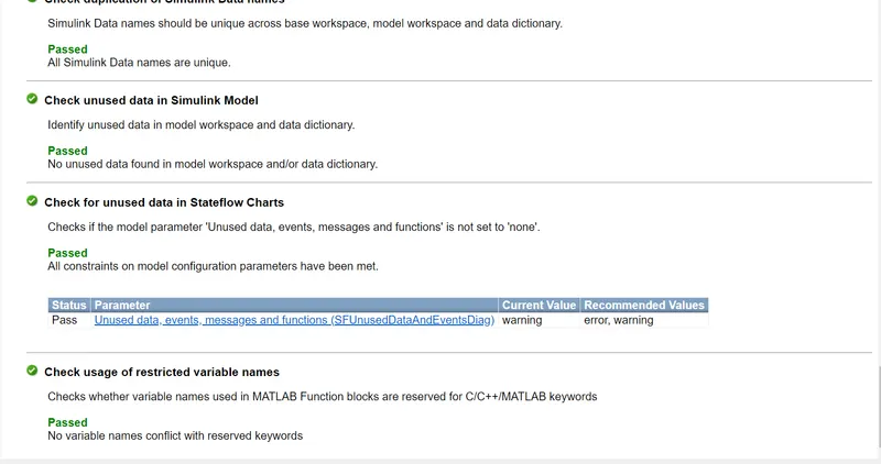
  Check duplication of Simulink Data names
Simulink Data names should be unique across base workspace, model workspace and data dictionary.

Passed
All Simulink Data names are unique.

  Check unused data in Simulink Model
Identify unused data in model workspace and data dictionary.

Passed
No unused data found in model workspace and/or data dictionary.

  Check for unused data in Stateflow Charts
Checks if the model parameter 'Unused data, events, messages and functions' is not set to 'none'.

Passed
All constraints on model configuration parameters have been met.


Status	Parameter	Current Value	Recommended Values
Pass	Unused data, events, messages and functions (SFUnusedDataAndEventsDiag)	warning	error, warning

  Check usage of restricted variable names
Checks whether variable names used in MATLAB Function blocks are reserved for C/C++/MATLAB keywords

Passed
No variable names conflict with reserved keywords
Harness test:
MIL test:
in this subsystem click on the right side showing a few options to select test harness.
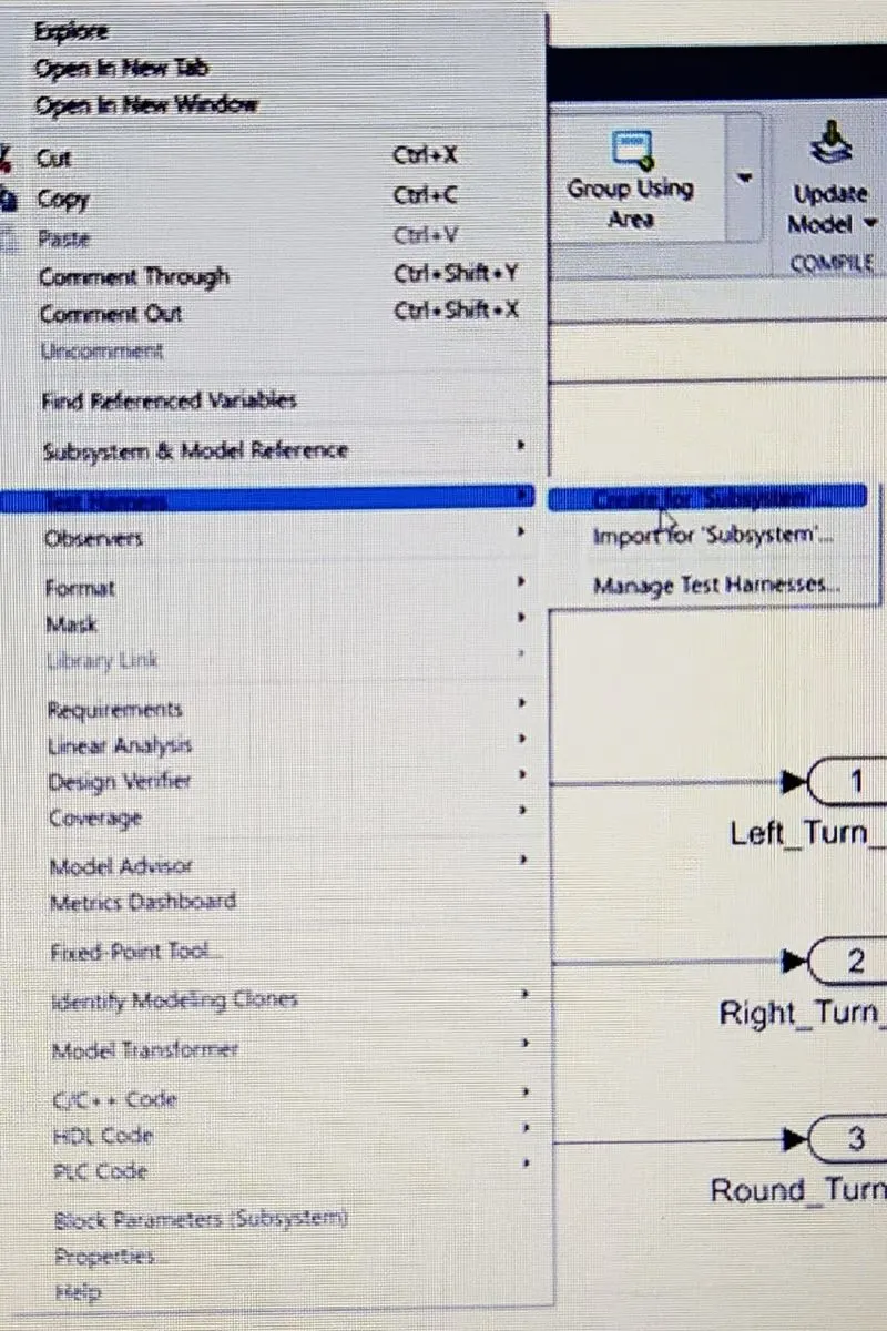
And change sources and sinks here input is a signal builder and output same.
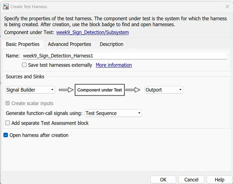
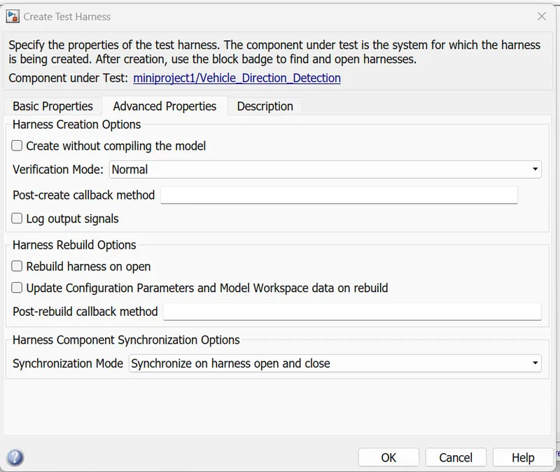
once click ok automatically opened another Simulink window showing like below fig.
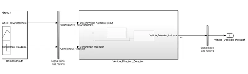
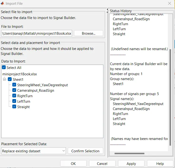
Time SteeringWheel_YawDegreeInput CameraInput_RoadSign RightTurn LeftTurn Straight
0	  30	     1	      1	      0	        0
1	  30	     1	      1	      0	        0
1	-120	     1	      0	      1         0
2	-120	     1	      0	      1	        0
2	   0	     1	      0	      0	        1
3	   0	     1	      0	      0	        1
3	  50	     0	      0	      0	        0
4	  50	     0	      0	      0	        0
open signal builder selects to import file.
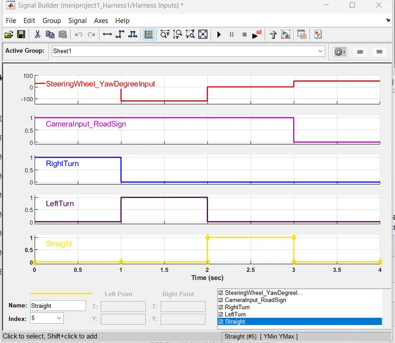
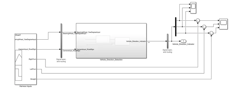
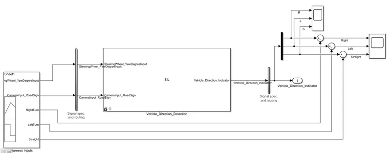
And I added Demux Block, sum block, and scope block to see the output result difference after adding these blocks model looks like the below fig.
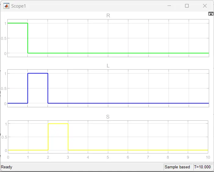
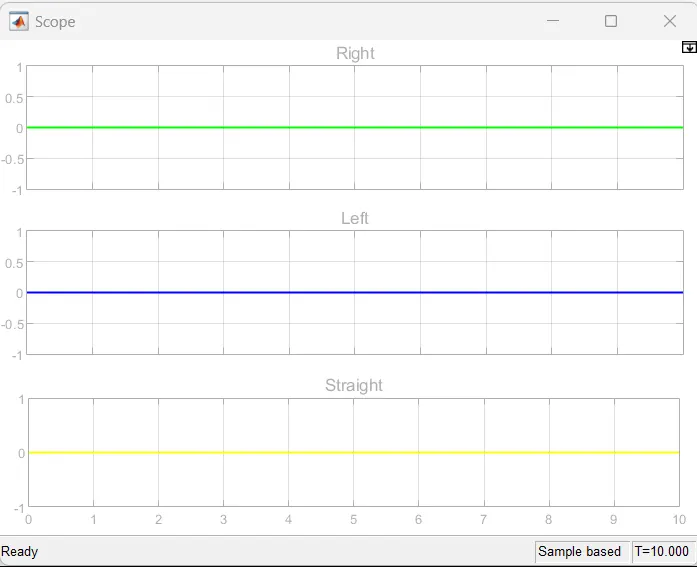
Comparing the signal builder and scope Graph is given below.
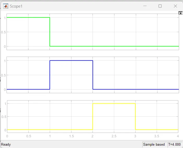
in the above figure, Green Line is the Right Turn, Blue Line is LeftTurn, Yellow Line is the Straight Turn
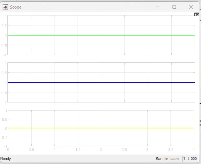
in the above figure, Green Line is Right Turn, Blue Line is LeftTurn, Yellow Line is Straight Turn.
SIL Test:
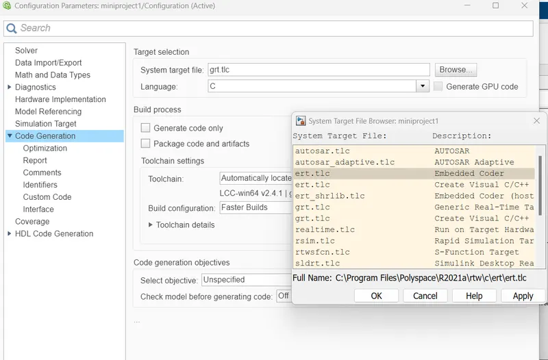
change solver settings and code generation settings
Time SteeringWheel_YawDegreeInput CameraInput_RoadSign RightTurn LeftTurn Straight
0	  30	     1	      1	      0	        0
1	  30	     1	      1	      0	        0
1	-120	     1	      0	      1         0
2	-120	     1	      0	      1	        0
2	   0	     1	      0	      0	        1
3	   0	     1	      0	      0	        1
3	  50	     0	      0	      0	        0
4	  50	     0	      0	      0	        0
Change the Block parameters check Treat as atomic unit option
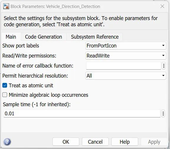
And this subsystem clicks on the right side showing a few options to select test harness.
And change sources and sinks here input is a signal builder and output same.
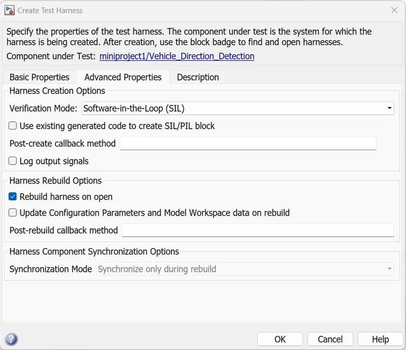
once click ok automatically opened another Simulink window showing like below fig.
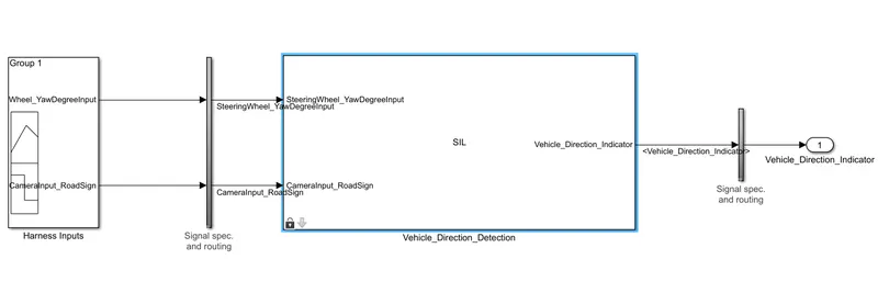
open signal builder selects to import file.
And I added Demux Block, sum block, and scope block to see the output result difference after adding these blocks model looks like the below fig.
Comparing the signal builder and scope Graph is given below.
Conclusion:
As for the result, Autonomous vehicles consist of various Advanced Driver-Assistance System (ADAS) features. Vehicle Direction Detection is one of the features of vehicles. I created a Simulink model of Vehicle Direction Detection as per the Requirement data And I created code generation and MIL Test, and SIL Test.
THANK YOU!😊🙏.